
- Article

28 Pages
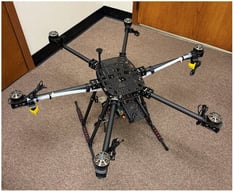
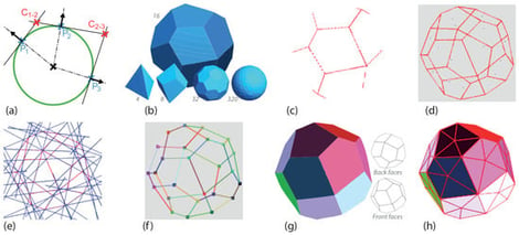
Lightweight UAVs increasingly operate in constrained environments, where even minor collisions can damage exposed propellers, arms, sensors, or embedded components. Designing protective cages for such platforms requires more than adding an external shell: the structure must preserve propeller clearance, fit the chassis, remain lightweight, avoid obstructing sensors and cameras, and remain feasible to prototype. This paper introduces PICLIN (Pipeline for Incremental Constraint-Linked InnovatioN), a graph-based design-to-prototyping workflow for UAV protective cages. PICLIN starts from abstract topological representations and progressively constrains them through geometric deployment, curved-surface embedding, numerical refinement, drone-integrated verification, and physical realization. The approach is demonstrated through a UAV case study leading from graph exploration to assembled protective prototypes. Results show that PICLIN generates coherent cage configurations while preserving early-stage design freedom and reducing the solution space toward manufacturable structures. For the representative Optimal 9 prototype, the cage mass was 151 g, excluding the current 28 g aluminium UAV interfaces, with an overall diameter of 485 mm and a design clearance of 50 mm between the propellers and the protective cage. A preliminary 1 m drop test of the 1.186 kg cage–chassis assembly, corresponding to an impact energy of approximately 11.6 J, produced a peak acceleration of approximately 35 g over an impact interval of about 15 ms. These measurements are reported as proof-of-feasibility results rather than as a complete mechanical validation. The contribution is not a single optimized cage geometry, but a reusable workflow linking abstract graph modeling, constraint integration, UAV-specific verification, and prototype-oriented realization.
Drones
28 September 2026
![Schematic of the rotational 5-fold validation scheme applied within each source dataset’s non-test trajectories. Segment sizes shown are illustrative, not to scale. The test partition is fixed per source at approximately 10% of trajectories, as summarized in Table 2. The validation segment rotates among the remaining folds. Adapted from the segmentation scheme of Mirzaei et al. [25].](https://mdpi-res.com/cdn-cgi/image/width=281%2Cheight=192/https://mdpi-res.com/drones/drones-10-00732/article_deploy/html/images/drones-10-00732-g001-550.jpg)