Article

Implementation of Synchronous Micromotor in Developing Integrated Microfluidic Systems

by
Ala'aldeen Al-Halhouli
1,2,*,
Stefanie Demming
1,
Andreas Waldschik
1 and
Stephanus Büttgenbach
1
1
Institute of Microtechnology, Technische Universität Braunschweig, Langer Kamp 8, 38106 Braunschweig, Germany
2
Mechatronics Engineering Department, German Jordanian University, Amman 11180, Jordan
*
Author to whom correspondence should be addressed.
Micromachines 2014, 5(3), 442-456; https://doi.org/10.3390/mi5030442
Submission received: 5 May 2014 / Revised: 8 June 2014 / Accepted: 7 July 2014 / Published: 18 July 2014
(This article belongs to the Special Issue 15 Years of SU8 as MEMS Material)

Abstract

:
This paper introduces the synchronous micromotor concept and presents new investigations on its application as an integrated driving mechanism in microfluidic systems. A spiral channel viscous micropump and a microstirrer are considered and tested as examples to verify the concept. The fabrication technology of such integrated systems is based on UV depth lithography, electroplating and soft lithography. The synchronous micromotor consists of a stator including double layer coils, and a rotor disk containing alternate permanent magnets. The coils are distributed evenly around the stator and arranged in three phases. The phases are excited by sinusoidal currents with a corresponding phase shift resulting in a rotating magnetic field. Regarding the spiral channel viscous micropump, a spiral disk was fixed onto the rotor disk and run at different rotational speeds. Tests showed very promising results, with a flow rate up to 1023 µL·min−1 at a motor rotational speed of 4500 rpm. Furthermore, for the application of a microstirred-tank bioreactor, the rotor disk design was modified to work as a stirrer. The performance of the developed microbioreactor was tested over a time period of approximately 10 h under constant stirring. Tests demonstrated the successful cultivation of S. cerevisiae through the integration of the microstirrer in a microbioreactor system. These systems prove that synchronous micromotors are well suited to serve as integrated driving mechanisms of active microfluidic components.

1. Introduction

For marketing purposes, new technical products should demonstrate extensive functionality, high reliability, low power consumption, and portability wherever applicable. There are two approaches to meet these challenges. The first is the mechatronics approach. It stands for the synergistic integration of mechanics, electronics, control theory, and computer science within product design and manufacturing [1]. This concept leads to improved technical performance. The second is the microtechnology approach. This approach can be used to miniaturize mechatronics products; thereby, it provides additional potential for the creation of high-quality products. The latter approach has caused the rapid development of micromechatronics technology, which integrates signal processing with miniaturized sensors and actuators. Today, micromechatronic systems play an important role in many fields of application such as automotive engineering, communication technology, biomedical engineering and environmental protection.
In the last decade, extensive work on micro-sensors has taken place. As a result, highly advanced microsensors have been developed with well-founded scientific theory and understanding. On the other hand, microactuators are still in an early stage of development. Microactuation allows for numerous new applications of micromechatronic systems. They have become key elements, for example, in micropositioning and microhandling systems [2] as well as in microfluidic devices.
Initially, electro-static and thermomechanical principles have been applied to microactuation due to the fact that all fabrication processes for these microactuators were available from integrated circuit technology. More sophisticated principles such as piezoelectricity, shape memory alloys, and magnetism emerged more slowly.
At an early stage of development, a number of publications presented arguments favoring electrostatic over magnetic microactuation [3]. Nevertheless, magnetic microactuators offer considerable performance advantages [4,5], for example large actuation forces, large deflections, low driving voltages resulting from low input impedances, and robustness under harsh environments. However, the fabrication process is technologically challenging for many reasons. Key elements of magnetic microactuators are three-dimensional microcoils and sophisticated hard and soft magnetic microstructures, which correspond to wound coils and magnets in bulk actuators. In order to achieve high forces, both the electric conductors of the microcoils and the magnetic flux guide structures need to provide large cross sections to allow for sufficiently high current and magnetic flux, respectively. Problems also originate from the thickness of the dielectric layers serving as both insulation and planarization layers. These features demand high aspect ratio fabrication processes.
Recently, much progress has been achieved concerning the fabrication of magnetic microactuators. Applying UV depth lithography based on new types of photoresists [6], micro-electroplating techniques and micromachined polymer magnets linear and rotational micromotors have been developed [2]. Three drive schemes are of particular importance: the variable reluctance stepping motor, the hybrid stepping motor and the synchronous motor [7]. Stepping motors exhibit the capability of rather small incremental motion, whereas for synchronous motors the simple design is advantageous.
The integration of the driving mechanism on the same chip offers considerable reduction of the overall chip size and its packaging complexity. Due to their unique performance as integrated driving mechanisms of active components and systems, magnetic microactuators such as synchronous micromotors promise novel applications in active microfluidic devices such as micropumps, microvalves and micromixer.
This work provides a brief review on selected examples of externally driven microfluidic systems, and reports on the synchronous micromotor concept and fabrication. In addition, it reviews recently published micropumping concepts driven by the synchronous micromotors and describes new biotechnological application of synchronous micromotor as a microstirrer for microbioreactor providing continuous homogenization of biomass suspension. It also presents the successful testing of a spiral channel micropump.

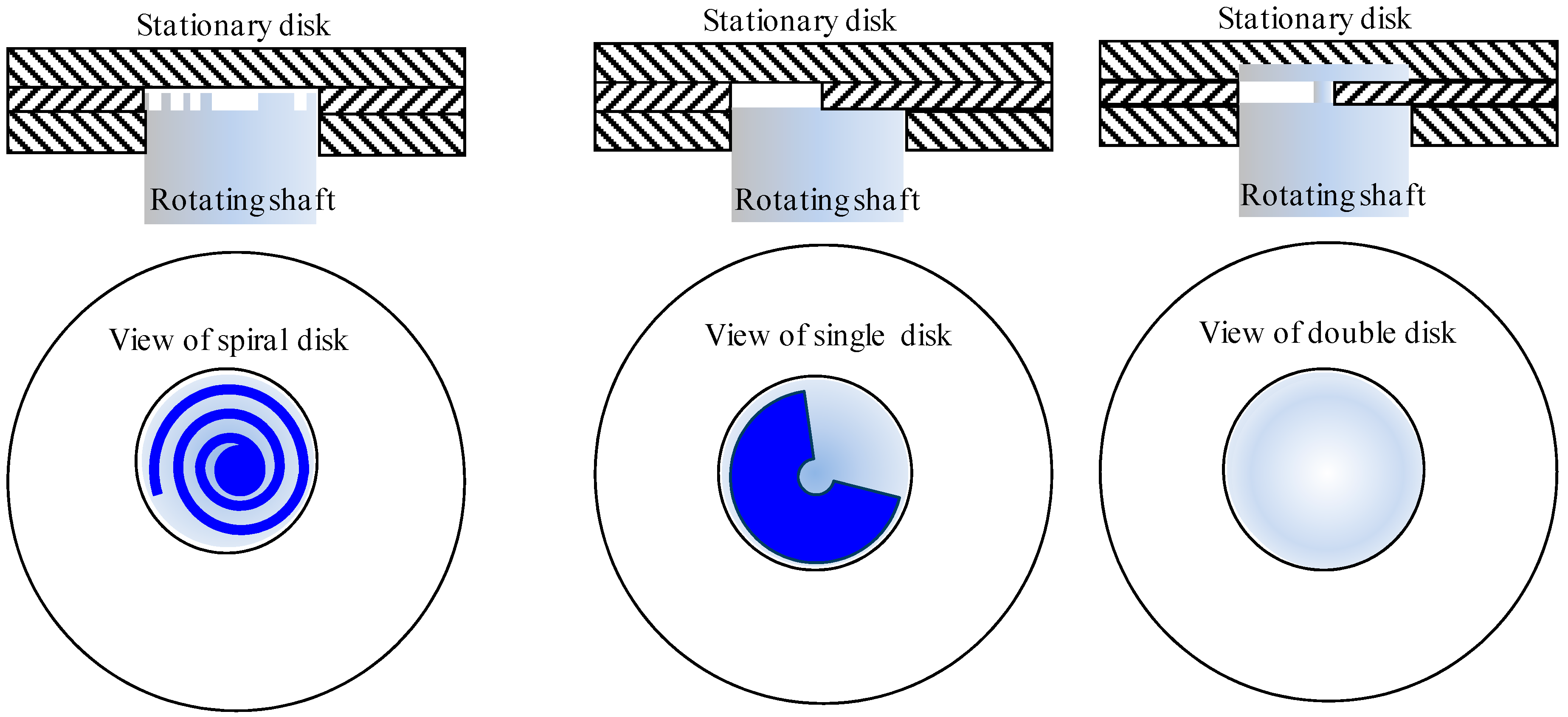
2. Externally Driven Microfluidic Systems

Viscous micropumps are pumps that use viscous stresses to transport fluid between inlet and outlet ports (e.g., spiral-channel, single and double disk micropumps) [8]. They are composed of rotating disk(s), a curved channel circular/spiral, and inlet and outlet ports located at the ends of the channel, which allow constant pumping flow rates (Figure 1). Due to the dominant viscous forces, the fluid is dragged between the inlet and outlet ports through rotating the spiral channel below a flat plate or the single/double disks in close proximity to the circular channel.
Figure 1. Schematic of viscous micropumps concept (Spiral-channel, single disk and double disk).
Micromachines 05 00442 g001
As shown in Figure 1, the area bounded between the channel walls and the disk(s) form the pump chamber. Quantitative lists of viscous micropumps geometrical dimensions, operating speeds and flow rates are provided in Table 1.
Table 1. Quantitative list of viscous micropumps.
ReferencePump typeRotor materialFluidw (rpm)Drotor (mm)Qmax (mL·min−1)
Blanchard et al., 2005 [9]Single diskstainless steelWater50002.381.00
Blanchard et al., 2005 [9]Double diskstainless steelWater50002.382.10
Blanchard et al., 2006 [10]Single diskPEEK plasticWater500010.164.75
Haik et al., 2007 [11]Spiral channel-Water120025.446.66
Al-Halhouli et al., 2008 [12]Spiral channelAluminiumGlycerin4285103.05
Al-Halhouli et al., 2009 [8]Spiral channelSU-8Glycerin306561.17
Lei and Li, 2004 [13]Vortex pumpcopperWater-4.52.45
Waldschik and Büttgenbach [14]Micro gear pumpSU-8Water1507.5–100.15
PresentSpiral channelSU-8Water45004.51.02
The single disk micropump was implemented, for real application, for characterizing the failure of an array of SU-8 microstructures. The mechanical microstructures were fabricated on the rotating disk with dimensions of 290 µm in length and 100 µm in height [15]. The structure’s failure was found to occur generally between 12,000 and 120,000 cycles, and was attributed to fluid shear stress, and to centrifugal forces due to disk rotation.
Even though these micropumps offer great potential in biotechnological applications, where manipulation of viscous fluids is required, they suffer from some mechanical problems, such as the need for external driving motor and leakage from the shaft connecting the rotor and the motor.
Another interesting concept is the polymer based vortex micropump that converts kinetic energy into fluid power through rotating a straight copper blade impeller sets into circular pump chamber. The impeller is driven by an external DC motor and runs at different rotational speeds. The fluid enters the pump through an inlet near to the pump center and moved toward to the outer diameter of the pump chamber [13]. The pump flow rates have been measured experimentally, where a maximum flow rate of 2.45 mL·min−1 has been reached at zero back pressure and at an operating voltage of 3 V. The minimum recorded flow rate was 0.02 mL·min−1 at a startup voltage of 0.5 V. The maximum recorded pumping pressure was 7105 Pa at 2 V [13].
The pump was proposed to be suitable for digitally controllable integrated microfluidic systems where controllable micro fluidic delivery and transport are required. Therefore, a concept validation prototype that consists of two vortex micropumps, two tesla valves and a “Y” shaped microchannel was assembled and tested in a chip. The aim of this test was controlling and manipulating the flow of water and red ink liquids in the Y shaped branches. Results showed that due to the fast response of the vortex, micropump liquids can be swapped in the desired microchannel by controlling the higher pumping pressure of that liquid [13]. The proposed system requires two pumps, and accordingly two external prime movers (DC motors). The blade’s micro-impeller is made from copper, which makes it less suitable for biotechnological applications where biocompatible materials are required. In addition, external driving motors make the chip larger in size and more complicated in packaging and the risk of leakage becomes much higher.

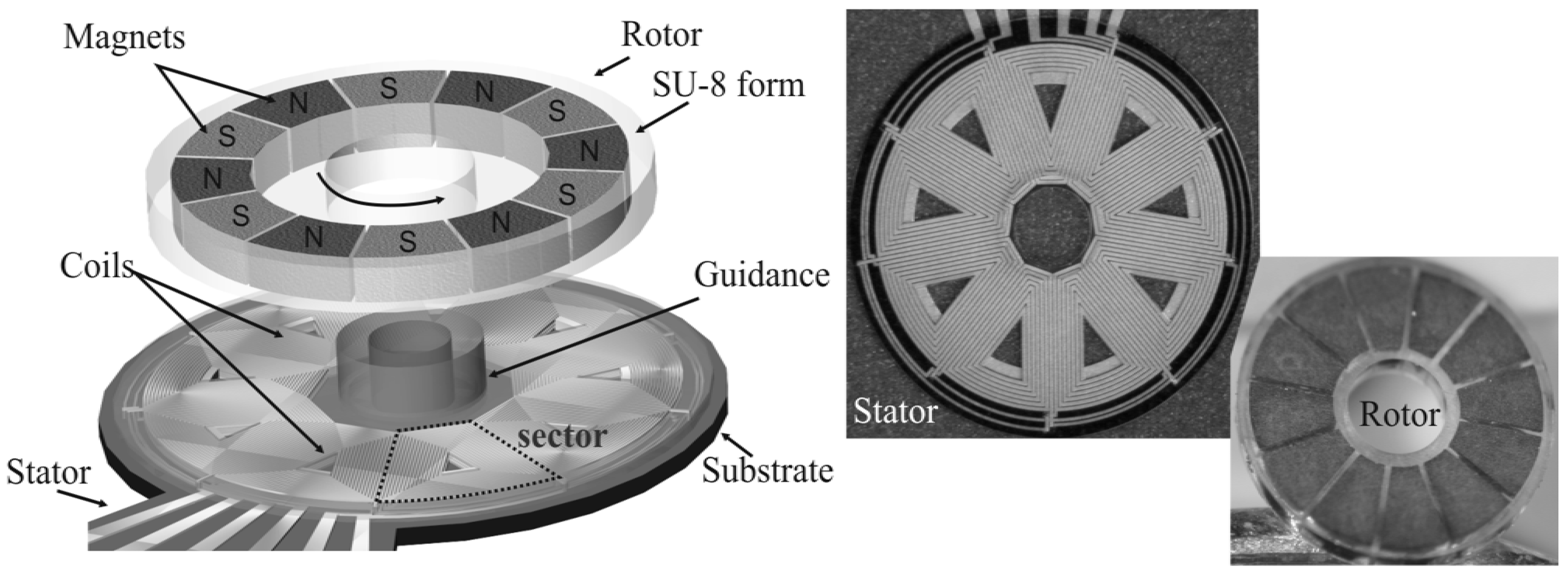
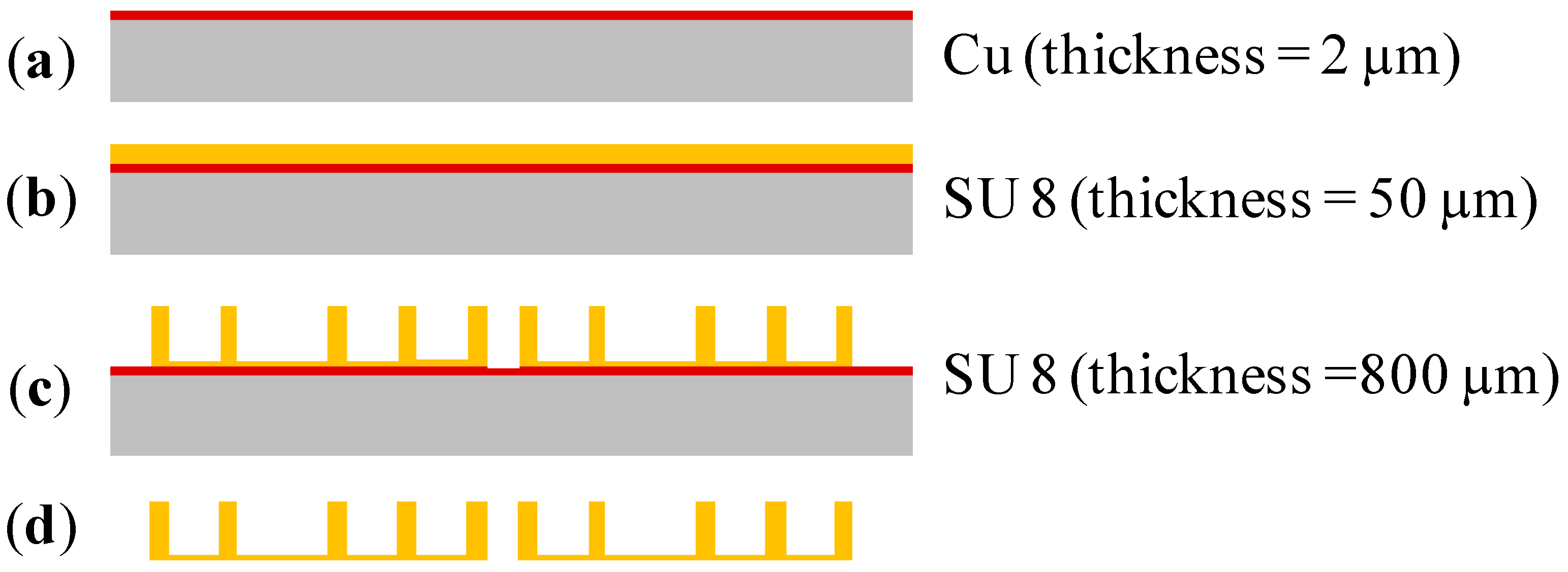
3. Synchronous Micromotors Concept and Fabrication

The synchronous micromotors are similar to typical macro models and consist of the stator and the rotor (Figure 2, left). The stator includes double layer spiral coils that are evenly distributed around the stator. Each layer consists of nine coils of 6–30 turns depending on system diameter and coil configuration (Figure 2, right). The conductor width is 30 µm separated by 10 µm insulation. The coils are connected to each other to provide a three-phase coil system. The phases are excited by sinusoidal currents with a corresponding phase shift resulting in a rotating magnetic field.
Figure 2. Concept and fabricated components of rotating synchronous micromotors [16].
Micromachines 05 00442 g002
In the center of the stator, an SU-8 guidance structure is integrated for rotor assembling. The rotor composed of alternate polymer magnets inserted in an SU-8 mold. These magnets are alternately magnetized in axial direction. Therefore, the rotor follows the stator rotating field synchronously in operational mode. The driving speed depends on the frequency of the current. Maximum speeds of 7000 rpm were reached using operational currents between 20 mA and 300 mA. Figure 2 illustrates the concept (left) and the fabricated components (right) of rotating synchronous micromotors [16].
Since the fabrication technologies of these components have been extensively described in detail elsewhere [16], in this paragraph only a short summary will be given.
The excitation coils are made of Cu that are manufactured by micro-electroplating using an appropriate electroplating bath after depositing a seed layer of 10 nm Cr and 275 nm Cu. The coils feature the smallest structure dimensions down to 10 µm line width with a gap of 10 µm. The temporary electro-plating molds are made of the positive tone resist AZ9260 using UV depth lithography. AZ9260 is a highly viscous diazonaphthoquinone based resist that allows exposure of thick layers of resist.
For embedding and insulation the epoxy based negative tone resist SU-8 has been used, which fills the gaps between the coil conductors. Cured SU-8 forms a highly cross-linked matrix of covalent bonds resulting in glass-like mechanical properties and high chemical and thermal stability [16]. The processing technology has been optimized achieving aspect ratios of up to 66 µm in 600 µm thick resist layers. Due to its viscous properties, SU-8 also exhibits an excellent planarization performance. Alternatively to the use of SU-8, plasma enhanced chemical vapor deposited low-stress Si3N4 has proved to act as an excellent insulation material. The main advantage of Si3N4 is that thinner films compared to SU-8 are required when used as insulation material between two coil layers of 15 µm thick copper layer. Furthermore, Si3N4 serves as an intermediate layer for the bonding of SU-8 with polydimethylsiloxane (PDMS), which is a commonly used material for lab-on-a-chip applications.
Permanent magnets are important components of magnetic microactuators due to their potential for larger forces and larger deflections. In order to be able to integrate permanent micromagnets of arbitrary shape and high thickness, a special lift-off process has been developed. A hard magnetic powder is mixed with a polymer. Ceramic ferrites with particle size of about 1 µm and rare earth alloys with particle sizes between 6 µm and 9 µm have been investigated at concentration levels of up to 90 weight percentages. More details on polymer magnets’ fabrication are available in [17].
The pasty hard magnetic composite is filled into SU-8 molds, which are patterned using UV depth lithography. In the SU-8 lithography process, the height of the magnets is adjustable depending on the dimension of the required magnets. The manufactured maximum structural height amounts to 600 µm. The magnetization process is carried out with special equipment that consists of a coil wound around a soft magnetic core with an integrated air gap. The current feed of the coil enables a tunable magnetic flux density in the air gap where the polymer magnet is inserted. After magnetization, permanent micromagnets with a residual induction were obtained which are dependent on the powder type and the dimensions of the magnets. Maximum values of 300 mT (NdFe), 200 mT (SmCo) and 120 mT (barium ferrites) are measured using vibrating sample magnetometer.

4. Micromotor Operated Microfluidic Systems

Reducing the dimensions of the microfluidic system driving mechanism offers the possibility of reducing the total system dimensions and hereby its packaging complexity. The successful development and implementation of synchronous micromotor as integrated driving mechanism of microfluidic systems would open new biomedical/biotechnological applications where manipulating of fluids of different viscosities is a big challenge. This section will report on previously published microfluidic devices/systems driven by integrated micromotors.

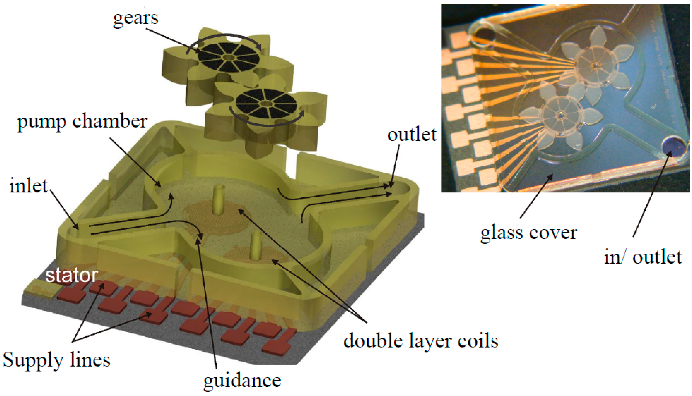
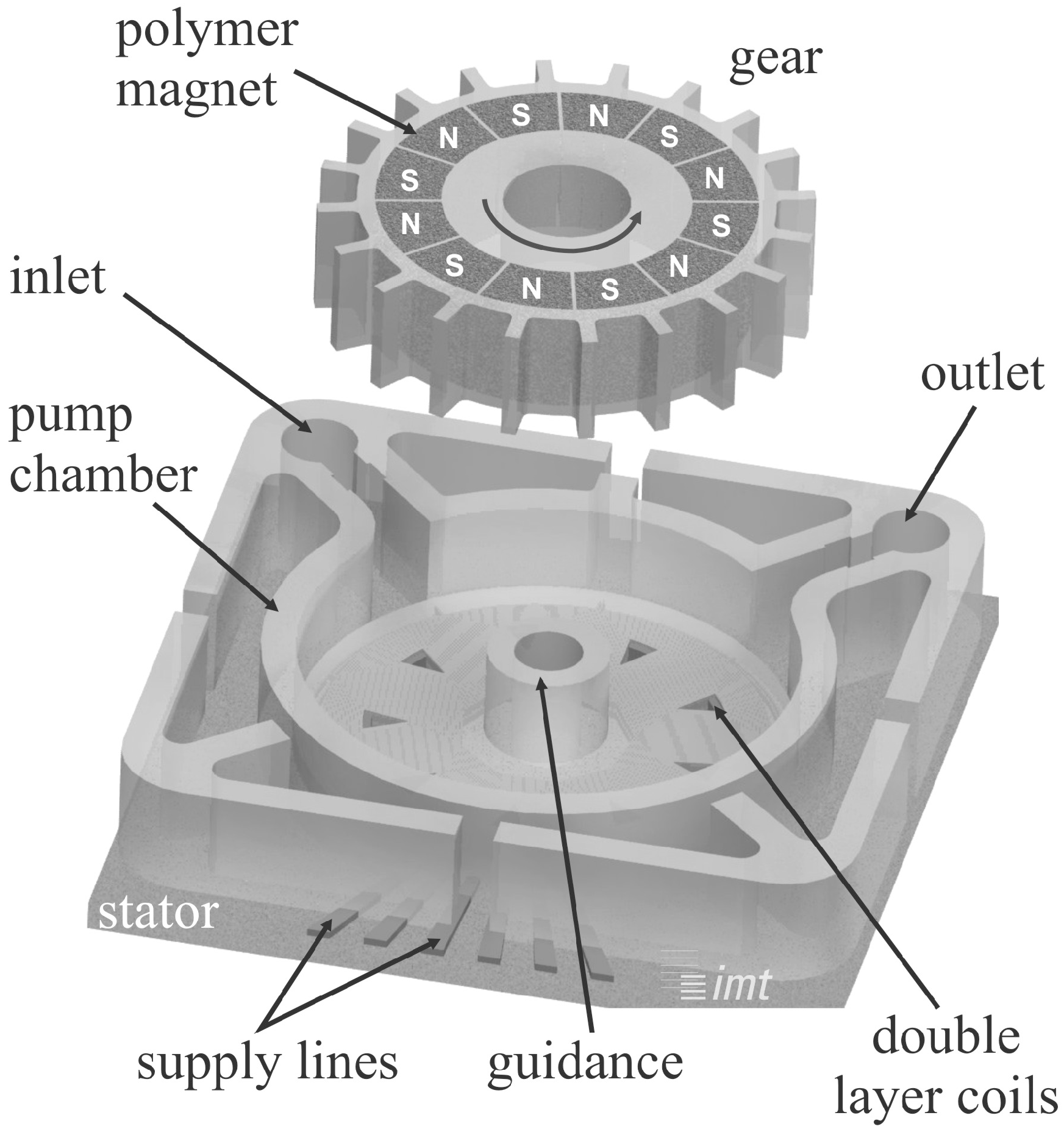
4.1. Micro Gear Pump

For the realization of the micro gear pump [14], two synchronous motors are combined and enclosed by an SU-8 chamber wall. Additionally, teeth with involute shape are placed on the outer diameter of the rotors forming gears (Figure 3 left). One gear driven by the three-phase system actuates the other gear which rotates in the opposite direction. While rotating, the fluid is drawn from the inlet, split to both gears and transported in the space between the teeth and the chamber wall. Both fluid streams are combined and displaced to the outlet. Because of the involute gearing, two teeth are in contact in the center line so that the return path is blocked. The system is closed by a structured glass cover which is fixed on the top of the chamber (Figure 3 right). The pump rate Micromachines 05 00442 i002 is approximated by:
Micromachines 05 00442 i001
where q is the number of spaces between two teeth, Ve is the volume of one space and depends on the height, diameter, module and number of teeth and N is the rotational speed.
Figure 3. Schematic view of the gear pump components (left) and the fabricated pump (right) [14].
Micromachines 05 00442 g003
For realizing different pump volumes, variations of gear design parameters were carried out. By doing so, miscellaneous gear pumps were fabricated with chamber lengths ranging between 7.5 mm and 10 mm and 300 µm in height providing theoretical pump rates in the range of 3.2–5.8 µL per revolution. In first tests, the pumps were successfully tested (Figure 3 left) with minimum current of 60 mA and maximum rotational speeds up to 1000 rpm. A pump rate of 150 µL·min−1 was obtained for one pump type at a rotational speed of 150 rpm [14].
The first experiments on integrating the synchronous micromotor concept in microfluidic systems have been successfully conducted on a micro gear pump. For the realization of the integrated micro pump, teeth of SU-8 with involute shape, similar to a gear shape, were designed and fabricated on the outer diameter of the synchronous motor rotor. Two of these gears were combined, assembled and enclosed by a structured glass in an SU-8 chamber. The gears are rotated in the opposite direction to enable transporting the fluid from the inlet to the space between the teeth and the chamber walls and then displaced to the outlet. The pump was run successfully for maximum rotational speeds up to 1000 rpm. However, a pump flow rate of 150 µL·min1 was achieved for only one type of developed pump dimensions at a rotational speed of 150 rpm [17].

4.2. Centrifugal Micropump

As for the centrifugal force pump, the rotor of the synchronous micro-motor was modified to take a toothed disc shape (gear) as shown in Figure 4 [18]. The rotor was mounted onto the stator and adjusted by an integrated guidance. The toothed rotor was made of alternate magnets, which were realized by using polymer magnet fabrication technology.
The pump was fabricated with diameters ranging between 3 mm and 8 mm, and pump chamber height of 300–400 μm. For the experiments, a water-ethanol-mixture was used as a working fluid. The pump chamber was filled with the fluid and the driving current was then increased incrementally. Tests showed that when the chamber was filled with fluid, 100 mA was required for continuous rotor rotation compared to tests without a fluid. The pump was successfully driven over a long period of time with variable rotating speed up to 4000 rpm. Although no flow rate measurements have been reported by this study, it was recommended to apply this actuation concept for biotechnological applications like the cultivation of bacteria or yeast cells where homogeneous nutrition supply is necessary for growing. This recommendation has been considered and tested as an application in this study.
Figure 4. Schematic view of the pumps centrifugal micropump [18]
Micromachines 05 00442 g004

5. New Applications of Synchronous Micromotors in Microfluidic Systems

Portable microfluidic lab-on-a-chip systems based on integrated driving mechanisms are highly challenging and still under development [19,20]. Most of these chips require microfluidic components for fluid handling applications such as pumping and mixing. However, several miniaturized components were driven with external actuators [21]. This section introduces the spiral channel viscous micropump and the microstirrer as microfluidic components that can be used as active integrated components in microfluidic systems.

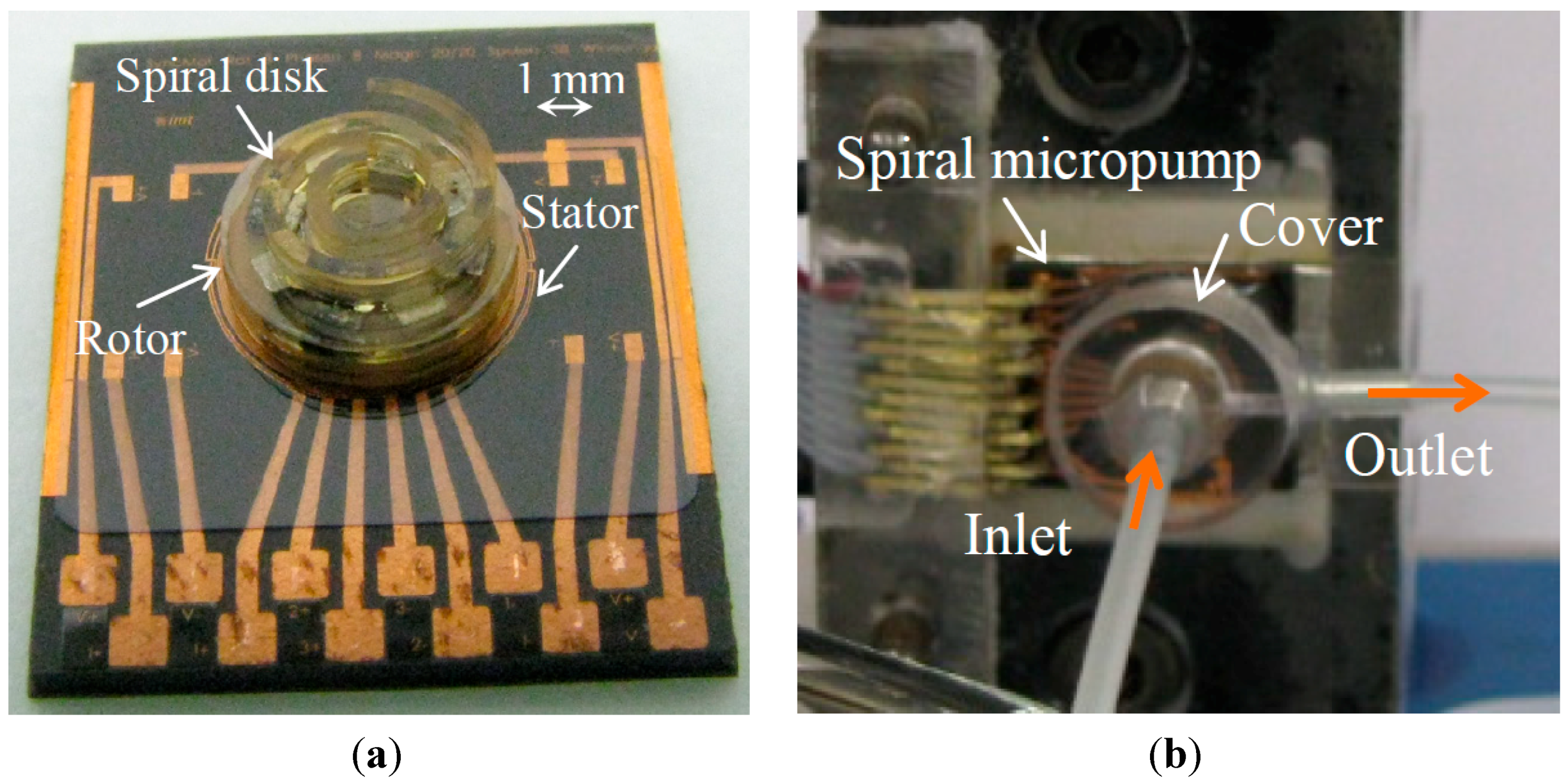
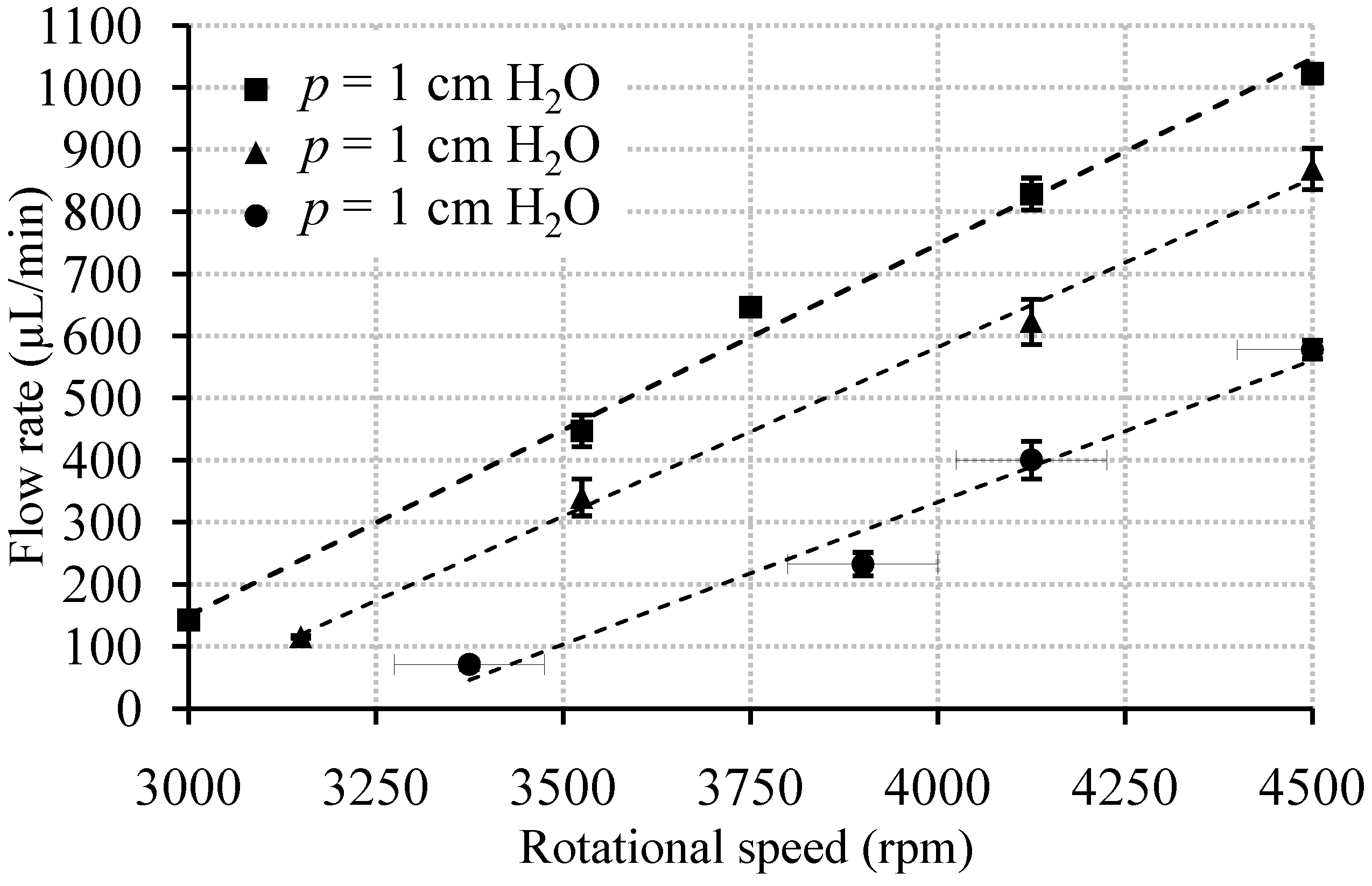
5.1. Spiral Channel Viscous Micropump

Generally, the spiral channel viscous micropump consists of a rotational spiral channel-disk, a flat cover, fluid inlet and outlet ports (Figure 5a), and a driving motor. The inlet and outlet ports are located at either ends of the spiral channel.
The spiral channel disk is driven by the motor and spins in close proximity to the flat cover. Consequently, the dominant viscous drag force between the rotational disk and the working fluid forces the flow to be in a direction tangentially to the element’s motion. This fact creates a Couette-Poiseuille-type flow in the pump chamber between the rotating element and the stationary surface of the cover [8]. The flow direction can be simply reversed by changing the spiral channel-disk rotational direction, i.e., clockwise (CW) or counter clockwise (CCW).
In this work, a microfabricated spiral pump with synchronous micromotors as an integrated driving mechanism has been successfully developed and tested. It comprises a spiral channel disk, a polycarbonate cover including fluid inlet and outlet ports, and a synchronous micromotor (Figure 5b).
The spiral channel disks were fabricated of SU-8 photoresist using UV depth lithography. Their fabrication process begins by electroplating first a 2 µm sacrificial copper layer onto a ceramic substrate (Figure 6a). A 50 µm SU-8 layer which serves as a base plate is then patterned (Figure 6b); after that, a thick SU-8 layer is spun onto and structured to provide the spiral channel pattern (Figure 6c); by etching the sacrificial layer the spiral channel disks are detached from substrate (Figure 6d).
The spiral channel disk has a diameter of 4.5 mm. The spiral groove forming the spiral channel has a channel width of 400 µm, a height of 800 µm, an angular span of 2π, an inner radius of 1090 µm, and an outer radius of 1770 µm.
Figure 5. Photos of the integrated spiral channel micropump components (a) and its final mounted view (b).
Micromachines 05 00442 g005
Figure 6. SU-8 spiral channel disks fabrication process plan. (a) Cu sacrificial layer; (b) SU 8 base plate; (c) Spiral channel patters; (d) free spiral disks.
Micromachines 05 00442 g006
The assembly of the micropump begins by fixing the SU-8 spiral channel disk onto the rotor segment of the micromotor using a silicone adhesive. Then, this assembly is adjusted on the stator according to the guidance structure. All adjustment steps were done carefully under microscope.
After ensuring the functionality of the motor rotation, a polycarbonate housing including the inlet and outlet ports is fixed onto the stator. Finally, the inlet tube is connected to the fluid reservoir, which is large enough to avoid level changes during operation. The outlet tube is connected to the collection reservoir placed onto a digital balance. The pumping flow rate is then measured by recording the balance reading at fixed intervals of time. Water was used as a working fluid.
The experimental parameters are the motor speed (spiral channel disk speed) and the pressure at the outlet port (back pressure). The speed ranges between 3000 rpm and 4500 rpm. Experiments were run at different back pressures p that had been realized by level differences between the inlet and the outlet. Readings have been taken after ensuring steady state flow conditions, where the pumped fluid is collected for a fixed interval of time, and the average flow rate is then estimated.
Figure 7 shows the nearly linear relation between rotational speed and the flow rate for different back pressures. This supports the validity of implementing the linear lubrication model, which considers dominant viscous force effects, in modeling the flow field in the spiral channel viscous micropump [22]. The maximum flow rate of 1023 µL·min1 was achieved at a motor rotational speed of 4500 rpm corresponding to an applied current of 50 mA.

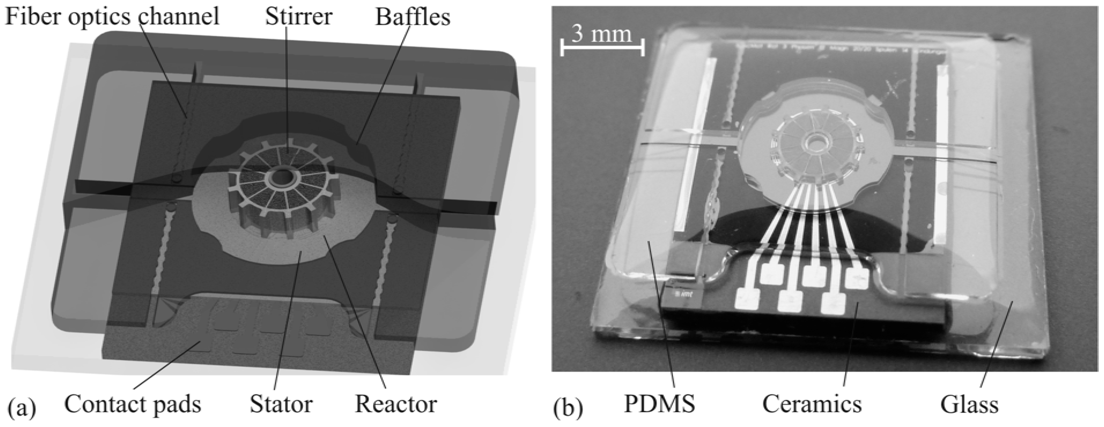
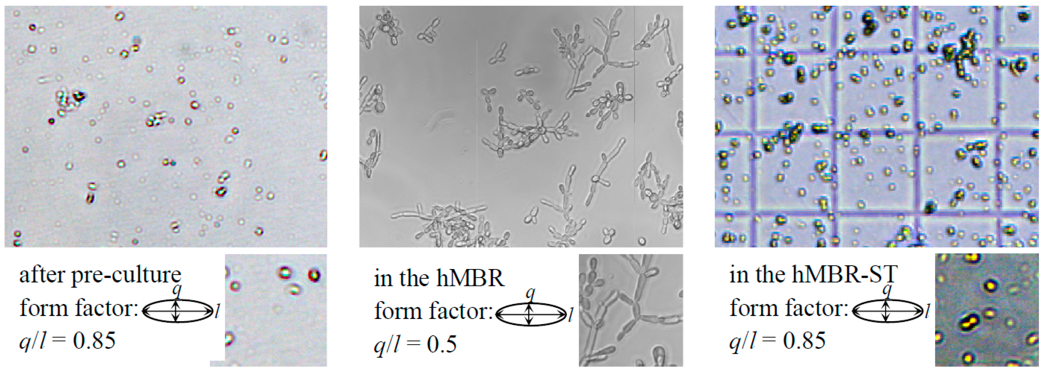
5.2. Microstirrer for Microbioreactor Application

In order to screen microorganisms with respect to reaction kinetics, the presence of homogeneous biomass suspension is essential. Homogenization of cell suspension can be improved with an integrated microstirrer, similar to commonly used bioreactors on the macroscale. These reactor systems have been scaled down by different research groups [23]. However, microtechnological processes were exclusively employed for the microfluidic structures, whereas commercially available miniature stirrers were subsequently assembled and externally actuated via commercial magnets or coils. This limits the integration level and thus the size reduction of the microbioreactors.
Figure 7. Flow rate against rotational speed for different back pressures p.
Micromachines 05 00442 g007
Few attempts to minimize the size of the stirrer have been reported. It has been mentioned that such microcomponents have potential for being integrated into microsystems for biological applications, however, no biological experiments have been reported [24]. As an example, an electromagnetically actuated rotor to mix two liquid phases has been presented [25]. Its stirrer (400 µm in length and 15 µm in thickness) is rotated by an external magnetic field. Another miniaturization attempt has been conducted by [24]. They developed a micromotor equipped with a hydrogel actuator. The rotor is set in motion on a magnetic stirrer platform. Results showed the feasibility of controlling fluid mixing at the microscale using poly(NIPAAm) posts.
This study aims at adapting the synchronous micromotor for its application as a microstirrer in a microstirred-tank bioreactor where a considerable size reduction could be achieved. The developed microbioreactor comprises three basic elements: the stator, the rotor (stirrer) and the microvessel made of PDMS with integrated online analytics for biomass detection (Figure 8).
The stirrer is mounted on the stator, which includes the electrical conductors and double layer coil systems and is covered with the PDMS reactor vessel, as depicted in Figure 8. The vessel includes baffles in order to perturbate the rotating fluid profile in the round reactor. In addition, the PDMS layer includes photonic elements (channels for fiber optics and microlenses) to provide online optical density monitoring at the inlet and outlet of the microreactor [26]. The disk-shaped microrotor possesses flat panels located at the perimeter and resembles a disk stirrer from macroscale applications. The rotor contains alternating magnets with axial magnetization and is assembled onto the stator via an integrated guide made of SU-8. The actuator features double layer sector spiral coils. The arrangement of the coils and magnets allows driving through three phases. The fabrication processes for the rotor and the stator are explained in detail in [16].
Figure 8. Schematics (a) and image (b) of the microstirred-tank bioreactor comprising the stator, the rotor (microstirrer) and the PDMS microvessel with integrated online analytics.
Micromachines 05 00442 g008
The PDMS structure is demoulded with an SU-8 negative master, which is fabricated in a double lithographic process. The first layer (230 µm in height) includes the inlet and outlet channels with the optical structures, whereas the reactor vessel features a total height of 550 µm.
Before assembling the three basic elements (rotor, stator and PDMS chamber), Si3N4 (ca. 150 nm) was deposited on both the rotor and the stator through PECVD. This allows for direct bonding of PDMS onto SU-8 insulation layer after plasma activation. As SU-8 does not provide complete biocompatibilty which is essential for cell cultures, Si3N4 serves as an additional intermediate protection layer.
The ceramic baseplate of the stator was placed on a glass chip and fixed by pouring PDMS of same height as the ceramic baseplate. Once the PDMS was polymerized, the rotor was adjusted to the stator which is facilitated by the integrated guidance structures. Plasma activation and bonding of all three elements followed. The microstirred-tank reactor was finally equipped with inlet and outlet needles and holds a total volume of 13 µL.
Before cultivations of S. cerevisiae, the reactor was initially rinsed with ethanol for disinfection and flushed with sterile VERDYN-medium. The reactor chamber was then inoculated with a cell concentration of OD600 nm = 0.4. The microspectrometer (Ocean Optics, Dunedin, FL, USA) automatically recorded spectra for time intervals of 10 min (with an integration time of 7 ms). A microscopic camera (DigiMicro 1.3, Drahtlose Nachrichtentechnik GmbH, Hessen, Germany) simultaneously took pictures of the entire reactor vessel in order to survey the continuous movement of the stirrer and the possibility of its disruption due to generated bubbles. The actuator rotation was set to 120 rpm [27].
In the first cultivations of S. cerevisiae, the performance of the developed microbioreactor was successfully proven over a time period of approximately 10 h with constant stirring. Figure 9, right, illustrates the morphology of the produced biomass in the microstirred-tank reactor. Planktonic yeast cells with a form factor (ratio of the height q to the length l of the cell) of 0.85 were observed. This form factor is similar to that attained after the pre-cultivation conducted in shake flasks (Figure 9, left). Only minimal hyphal growing could be detected, which is usually observed in non-stirred microbioreactors as depicted in Figure 9, middle, [28]. In those cells, it tended to grow adhesively. The variance in morphology (0.85 in the microstirred-tank reactor compared to 0.5 in the non-stirred microbioreactor) is partially due to the convective fluid profile induced by the microstirrer. This again results in more homogeneous nutrient supply, which suggests submerged cultivation conditions and thus allows for the analysis of reaction kinetics of bioprocesses.
Figure 9. Cell morphology obtained after cultivation in: shake flask “pre-cultivation” (left), non-stirred microbioreactor [28] (middle), and microstirred-tank bioreactor (right).
Micromachines 05 00442 g009

6. Conclusions and Outlook for the Future

This paper presented the successful application of synchronous micromotors as integrated driving mechanism in active microfluidic systems (the spiral channel viscous micropump and a microstirrer). Synchronous micromotors rotated successfully the spiral channel viscous micropump up to 4500 rpm, where a flow rate of 1023 µL·min−1 was achieved at applied current of 50 mA. In addition, successful cultivation results of S. cerevisiae have been presented over a time period of approximately 10 h with constant stirring in a microbioreactor.
These results are motivating and encourage further efforts towards the development of electromagnetic based multifunction microfluidic platforms for lab-on-a-chip applications.

Acknowledgments

This work has been funded by the German Research Foundation (DFG) within the framework of the Collaborative Research Center SFB 516 Design and Manufacturing of Active Microsystems and the Research Unit 856 Microsystems for Particulate Life-Science Products. One of the authors (Stephanus Büttgenbach) gratefully acknowledges the financial support of the Volkswagen Foundation.

Author Contributions

Andreas Waldschik and Stephanus Büttgenbach designed and fabricated the synchronous micromotors, Ala’aldeen Al-Halhouli and Andreas Waldschik designed, fabricated and characterized the micropumps, Stefanie Demming designed and fabricated the microstirrer and conducted the cell culture experiments, Stephanus Büttgenbach supervised the projects at all stages.

Conflicts of Interest

The authors declare no conflict of interest.

References

  1. Draft translation of the French standard NF E 01-010. Available online: http://www.thesame-innovation.com/Publi/Fichier/NF E 01-010_draft_translation.pdf (accessed on 10 July 2014).
  2. Büttgenbach, S.; Burisch, A.; Hesselbach, J. Design and Manufacturing of Active Microsystems; Springer: Berlin, Germany, 2011. [Google Scholar]
  3. Trimmer, W.S.N.; Gabriel, K.J. Design considerations for a practical electrostatic micro-motor. Sens. Actuators 1987, 11, 189–206. [Google Scholar] [CrossRef]
  4. Busch-Vishniac, I.J. The case for magnetically driven microactuators. Sens. Actuators A 1992, 33, 207–220. [Google Scholar] [CrossRef]
  5. Cugat, O.; Delamare, J.; Reyne, G. Magnetic micro-actuators and systems (MAGMAS). IEEE Trans. Magn. 2003, 39, 3607–3612. [Google Scholar] [CrossRef]
  6. Lorenz, H.; Despont, M.; Fahrni, N.; Brugger, J.; Vettiger, P.; Renaud, P. High-aspect-ratio, ultrathick, negative-tone near-UV photoresist and its application for MEMS. Sens. Actuators A 1998, 64, 33–39. [Google Scholar] [CrossRef]
  7. Hansen, S.; Gatzen, H.H. Development and Fabrication of Linear and Multi-Axis Microactuators. In Design and Manufacturing of Active Microsystems; Büttgenbach, S., Burisch, A., Hesselbach, J., Eds.; Springer: Berlin, Germany, 2011; pp. 225–244. [Google Scholar]
  8. Al-Halhouli, A.T. Recent advances in on-disk viscous micropumps. J. Microelectron. Electron. Packag. 2009, 6, 1–9. [Google Scholar]
  9. Blanchard, D.; Ligrani, P.; Gale, B. Single-disk and double-disk viscous micropumps. Sens. Actuators A 2005, 122, 149–158. [Google Scholar] [CrossRef]
  10. Blanchard, D.; Ligrani, P.; Gale, B. Miniature single-disk viscous pump (Single-DVP), performance characterization. J. Fluids Eng. 2005, 128, 602–610. [Google Scholar] [CrossRef]
  11. Haik, Y.; Kilani, M.I.; Hendrix, J.; Al Rifai, O.; Galambous, P. Flow field analysis in a spiral viscous micropump. Microfluid. Nanofluidics 2007, 3, 5527–5535. [Google Scholar]
  12. Al-Halhouli, A.T.; Demming, S.; Feldmann, M.; Büttgenbach, S.; Kilani, M.I.; Al-Salaymeh, A. Performance characterization of a miniature spiral-channel viscous pump. Sens. Actuators A 2008, 142, 256–262. [Google Scholar] [CrossRef]
  13. Lei, K.; Li, W. Vortex Micropump for Integrated Optically Transparent Microfluidic Chips. In Proceedings of the IEEE International Conference on Mechatronics and Machine Vision in Practice, Macau, China, 29 November–2 December 2004; pp. 219–225.
  14. Waldschik, A.; Büttgenbach, S. Micro gear pump with internal electromagnetic drive. Microsyst. Technol. 2010, 16, 1581–1587. [Google Scholar] [CrossRef]
  15. Blanchard, D.; Ligrani, P.; Gale, B.; Harvey, I. Micro-structure mechanical failure characterization using rotating Couette flow in a small gap. J. Micromech. Microeng. 2005, 15, 792–801. [Google Scholar] [CrossRef]
  16. Waldschik, A.; Feldmann, M.; Seidemann, V.; Büttgenbach, S. Development and Fabrication of Electromagnetic Microactuators. In Design and Manufacturing of Active Microsystems; Büttgenbach, S., Burisch, A., Hesselbach, J., Eds.; Springer: Berlin, Germany, 2011; pp. 207–224. [Google Scholar]
  17. Al-Halhouli, A.T.; Kilani, M.I.; Waldschik, A.; Phataralaoha, A.; Büttgenbach, S. Development and testing of a synchronous micropump based on electroplated coils and microfabricated polymer magnets. J. Micromech. Microeng. 2012, 22. [Google Scholar] [CrossRef]
  18. Waldschik, A.; Büttgenbach, S. Fabrication of internally driven micro centrifugal force pumps based on synchronous micro motors. Microsyst. Technol. 2010, 16, 1105–1110. [Google Scholar] [CrossRef]
  19. Lee, C.; Chen, Z. Valveless impedance micropump with integrated magnetic diaphragm. Biomed. Microdevices 2010, 12, 197–205. [Google Scholar] [CrossRef] [PubMed]
  20. Cha, K.J.; Kim, D.S. A portable pressure pump for microfluidic lab-on-a-chip systems using a porous polydimethylsiloxane (PDMS) sponge. Biomed. Microdevices 2011, 13, 877–883. [Google Scholar] [CrossRef] [PubMed]
  21. Rhie, W.; Higuchi, T. Design and fabrication of a screw-driven multi-channel peristaltic pump for portable microfluidic devices. J. Micromech. Microeng. 2010, 20. [Google Scholar] [CrossRef]
  22. Kilani, M.I.; Al-Salaymeh, A.; Al-Halhouli, A.T. Effect of channel aspect ratio on the flow performance of a spiral-channel viscous micropump. J. Fluids Eng. 2006, 128, 618–627. [Google Scholar] [CrossRef]
  23. Schäpper, D.; Alam, M.N.H.Z.; Scita, N.; Lantz, A.E.; Gernaey, K.V. Application of microbioreactors in fermentation process development: A review. Anal. Bioanal. Chem. 2009, 395, 679–695. [Google Scholar] [CrossRef] [PubMed]
  24. Agarwal, A.K.; Atencia, J.; Beebe, D.J.; Jiang, H. Magnetically Driven Temperature-Controlled Microfluidic Actuators. In the Proceedings of 1st International Workshop on Networked Sensing Systems, Tokyo, Japan, 22–23 June 2004; pp. 51–55.
  25. Ryu, K.S.; Shaikh, K.; Goluch, E.; Fan, Z.; Liu, C. Micro magnetic stir-bar mixer integrated with parylene microfluidic channels. Lab Chip 2004, 4, 608–613. [Google Scholar] [CrossRef] [PubMed]
  26. Demming, S.; Llobera, A.; Wilke, R.; Büttgenbach, S. Single and multiple internal reflection poly(dimethylsiloxane) absorbance-based biosensors. Sens. Actuators B 2008, 139, 166–173. [Google Scholar] [CrossRef]
  27. Demming, S. Disposable Lab-on-Chip Systems for Biotechnological Screening. Ph.D. Thesis, Technische Universität Braunschweig, Braunschweig, Germany, 2010. [Google Scholar]
  28. Edlich, A. Entwicklung eines Mikroreaktors als Screening-Instrument für biologische Prozesse. Ph.D. Thesis, Technische Universität Braunschweig,, Braunschweig, Germany, 2010. [Google Scholar]

