Liquid Encapsulation in Parylene Microstructures Using Integrated Annular-Plate Stiction Valves

Abstract
: We report the design, fabrication and characterization of micromachined Parylene structures for self-sealing liquid encapsulation applications. Automatic sealing is enabled through the use of an integrated annular-plate stiction valve which greatly reduces device footprint over in-plane configurations. We achieve automatic wafer-level liquid entrapment without using adhesives or processing at elevated pressures or temperatures. The ability to track changes to the internal liquid volume through the use of electrochemical impedance measurements is also presented.1. Introduction
Many interesting MEMS applications such as variable-focus liquid lens optics [1], electrolysis actuators, and electrowetting devices employ encapsulated liquids [2]. These applications require appropriate fabrication techniques and structures for long term encapsulation of small liquid volumes. The application of thermal or chemical bonding techniques is often challenging as the liquid must be made compatible with the additional steps introduced into the process.
One such approach utilized thermo-compressive bonding of Parylene C to successfully encapsulate water within microreservoirs for several days [3]. The technique required thermal excursion >200 °C, and as such, the chemical stability of liquids other than water (or biologic material contained within: proteins, cells, etc.) remains a concern. Various room temperature techniques have been proposed to address this challenge including chemical vapor deposition of Parylene C directly on droplets of low vapor pressure liquids [1]. Others have exploited UV-curable resins to perform on-demand bonding-in-liquid with some success, however, alignment was found to be a critical factor [4]. Wafer-level room temperature sealing was demonstrated in gold microreservoirs patterned on silicon wafers and sealed through physical embossing of matching gold rings a glass sealing wafer. The seal was shown to be hermetic but the embossing process required high pressure, epoxy reinforcement and very smooth gold surfaces that were realized through additional lapping steps [5]. A sealing mechanism that introduces a minimum number of additional steps and simplifies the sealing process would be an attractive alternative to current methods.
Stiction has been investigated as a possible sealing mechanism due to its simplicity and notoriously strong surface interactions. Stiction is usually considered an unwanted failure mechanism in MEMS and can render devices inoperable unless accounted for appropriately [6,7]. This phenomenon, however, is beneficial when utilized as a sealing mechanism in valve structures for trapping fluid. Parylene-based stiction valves have demonstrated excellent performance in wafer-level sealing of liquids within microchambers [8,9], but are currently placed externally in relation to the liquid chamber and active structures of the device. This configuration increases the overall device footprint and limits the ability to tailor the microchamber characteristics since the shared fabrication steps must also satisfy the stiction valve design constraints. Decoupling the valve construction by integrating it within the active structure itself was attempted by [3] but liquid retention was limited to several minutes due to suboptimal valve design. Here we combine the optimal annular-plate valve design guidelines derived by [8] in an integrated device to reduce overall footprint by nearly 50% and achieve automatic long-term liquid encapsulation [10].
2. Design and Fabrication
2.1. Device Design
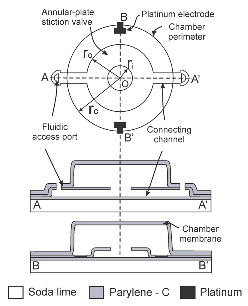
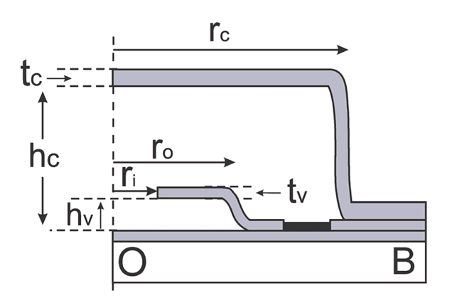
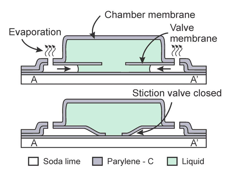
The fluid encapsulation device consists of three main components: (1) an annular-plate stiction valve; (2) peripheral fluidic access ports; and (3) a microchamber. The valve is connected via short microchannels to the fluidic access ports located on the periphery and base of the microchamber structure (Figure 1). Initially, the interior of the chamber and channels are filled with a sacrificial material. After removing the sacrificial layer using a wet solvent, the chamber is filled by passive soaking at the wafer level in the desired filling solution. Removal from the bath and exposure to ambient conditions induces evaporation through the peripheral access ports. The evaporating liquid fronts move along the connecting channels toward the stiction valve. The freed annular plate, if mechanically compliant, can be pulled down to contact the substrate by capillary forces and if the adhesion energy is large enough, will remained pinned to the substrate forming a seamless circumferential seal. The stiction-induced collapse and sealing of the integrated annular-plate traps the remaining liquid in the chamber above the plate (Figure 2).
2.2. Stiction Valve Design
Parylene-based stiction valves were designed according to the guidelines developed by Wang et al. [8,11]. Stiction occurs when the critical number, Nc, exceeds 1:
2.3. Fabrication
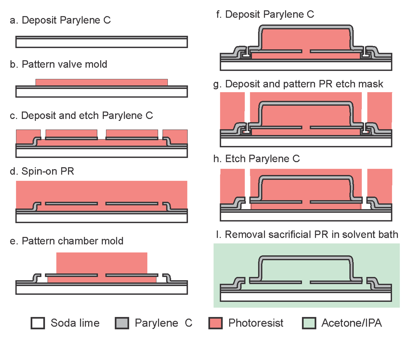
The entire fabrication process is realized at relatively low temperatures (90 °C) (Figure 4) which enables its use on a variety of polymer-based substrates and facilitates adoption in temperature sensitive processes. Standard soda-lime glass wafers were utilized as the carrier substrate. Fabrication began with optional platinum electrodes (2,000 Å) patterned on a 10 μm Parylene film followed by a 1 μm Parylene insulation layer. The 10 μm Parylene film allows for release/handing of structures and devices from the soda-lime carrier substrate for applications where flexibility is required. The optional electrodes are exposed to the liquid within the chamber and serve as an electrical interface for electrochemical measurement or actuation applications. In this work, electrodes were used for electrochemical measurements to track the sealing capability of the stiction valves and to monitor water vapor transmission through the Parylene film.
Photoresist was then spun-on and patterned (2 μm, AZ 4400, AZ Electronic Materials, Branchburg, NJ, USA) forming the sacrificial mold for the valve structure. Parylene was then deposited (2 μm) forming the valve membrane (tv) and sidewalls. Parylene over the valve center and access ports was removed in oxygen plasma (100 W, 100 mT) using a photoresist mask, thereby completing the annular valve structure (ri) and access ports. The exposed state of the sacrificial photoresist forming the valve layer (step c, d) made it difficult to remove the photoresist etch mask without erosion of the underlying valve structure. For this reason, the chamber sacrificial layer was spun and patterned directly on top of the etch mask (12 μm, AZ 4620, AZ Electronic Materials, Branchburg, NJ, USA), (rc = 150 μm). A 4.2 μm Parylene film was then deposited (tc) to enclose the chamber and a final Parylene etching step was necessary to re-open the fluidic access ports (step h). Test dies were then diced and following sacrificial photoresist removal in acetone, IPA, and DI water, the chambers were filled in a batch process by immersion in the desired fluid (DI water). Adhesion to the carrier substrate was realized through treatment of the carrier wafer with A-174 silane prior to deposition of the base Parylene layer. If desired, release from the soda-lime carrier substrate can be accomplished by skipping the A-174 treatment. This allows for a simple release from the substrate by cutting the Parylene film with a razor blade and peeling; a process that is greatly facilitated if performed under water.
3. Results and Discussion
3.1. Stiction Valve Sealing
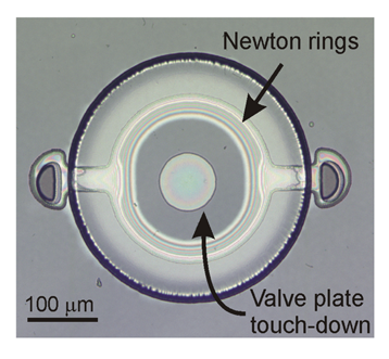
Stiction valve sealing and liquid encapsulation capability were evaluated by optical observation of a sample die containing several devices. The devices were filled, as described previously, with DI water. The die was then removed from the bath and exposed to ambient laboratory conditions (typically <5 min) to initiate the fluid encapsulation process. Following sufficient fluid evaporation, successful stiction valve sealing was observed and marked by the appearance of a dark central region indicating conformal contact between the annular plate and substrate. Emergence of interference rings between the central region and the peripheral plate anchors indicated proximity of the valve plate to the substrate as the valve plate transitioned from contact with the substrate to freestanding near the anchors (Figure 5). The mechanical deformation produced during stiction of the Parylene membrane is predominantly elastic in nature and is consistent with small deflection models that assume maximum deflections less than or equal to membrane thickness. Compared to more traditional diaphragm materials like silicon nitride (E∼300 GPa), the mechanical loading of the relatively soft Parylene material (E∼4 GPa) produces only nominal stresses that fall well below the yield point of the material, as verified through finite-element-modeling of membrane during deflection (data not shown here).
3.2. Liquid Encapsulation
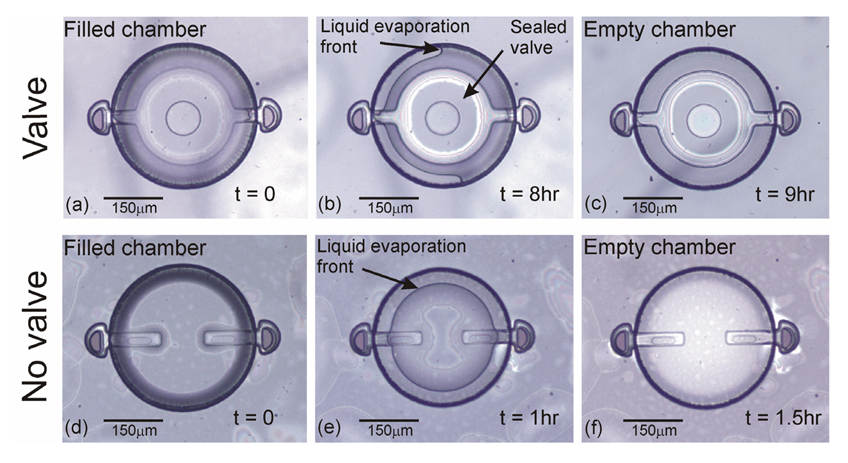
Successful encapsulation of liquid was evidenced by the appearance of a liquid front within the chamber after several hours of complete encapsulation. Initially, the chambers appeared uniform due to complete filling and entrapment of liquid within the chamber [Figure 6(a)]. This was followed by the appearance of a liquid front several hours later as a result of water vapor transmission [Figure 6(b)]. This is the first demonstration of uniform and complete device filling; in earlier attempts, air pockets were often observed and thus, liquid entrapment was incomplete [3,11]. For comparison, devices without a valve were also fabricated and tested [Figure 6(d–f)]. Within 1.5 h, valveless devices were completely dry while devices with a valve successfully encapsulated liquid up to 9 h at ambient conditions (20 °C, ∼30% RH). The formation of a liquid front, even in valved devices, clearly indicated that liquid loss still occurred. Water vapor transmission through the chamber membrane and not the valve seal was hypothesized to be the root liquid loss mechanism; however a method to quantitatively track internal volume was needed. The following section describes the use of electrochemical impedance to track liquid volume within the chamber.
3.3. Impedance-Based Volume Measurement
When metal electrodes are immersed in liquid, the spontaneous creation of the so-called double-layer interface is responsible for capacitive behavior at each electrode interface. In parallel with this capacitance is a charge transfer resistance which is typically very high and accounts for perturbations of the double-layer interface when a potential is applied. The bulk solution, however, behaves much like a liquid resistor that varies with path length and cross-sectional area, and lies in series with the interfacial components. Utilizing a simplified model of this interface based on Randle's equivalent circuit, the measured impedance can be expressed as:
The impedance of the liquid between the electrodes depends complexly on the volumetric conduction path of current-carrying ions in the solution as well as the total volume contained within the chamber. As volume is lost through water vapor transmission, the chamber's top surface deforms to accommodate the lost volume resulting in changes to the volumetric cross-section over time. During this liquid-loss phase, the impedance magnitude and phase vary due to changes in Rs which are directly related to the bulk liquid volume. The impedance magnitude and phase are expressed as follows:
In order to relate impedance with liquid volume, Rs needs to be determined. To make the analysis more tractable, a simplification of this system assumes that bulk resistance is inversely proportional to the cross-sectional area through the central axis of the chamber through the simple relation Rs≈ ρl/A, where l is the distance between electrodes and A, the cross-sectional area, is calculated through the center of the device. In reality, the solution resistance calculation requires a more complex expression that integrates the differential cross sectional area dA over a path dl that accounts for the changing membrane deflection profile with radius. The cross-sectional area through this mid section of the chamber can be easily calculated from the standard deflection equation for a circularly clamped membrane of uniform thickness given by:
Substituting y0= y(r = 0) (maximum membrane deflection) into Equation 6 yields:
Through a similar substitution into the simple area integral of Equation (5), cross-sectional area can be expressed in terms of maximum deflection as A = y0rc/10. Substituting in Equation (7) yields an approximation that is useful for relating chamber volume with solution resistance and ultimately impedance:
3.4. Liquid Loss Mechanism
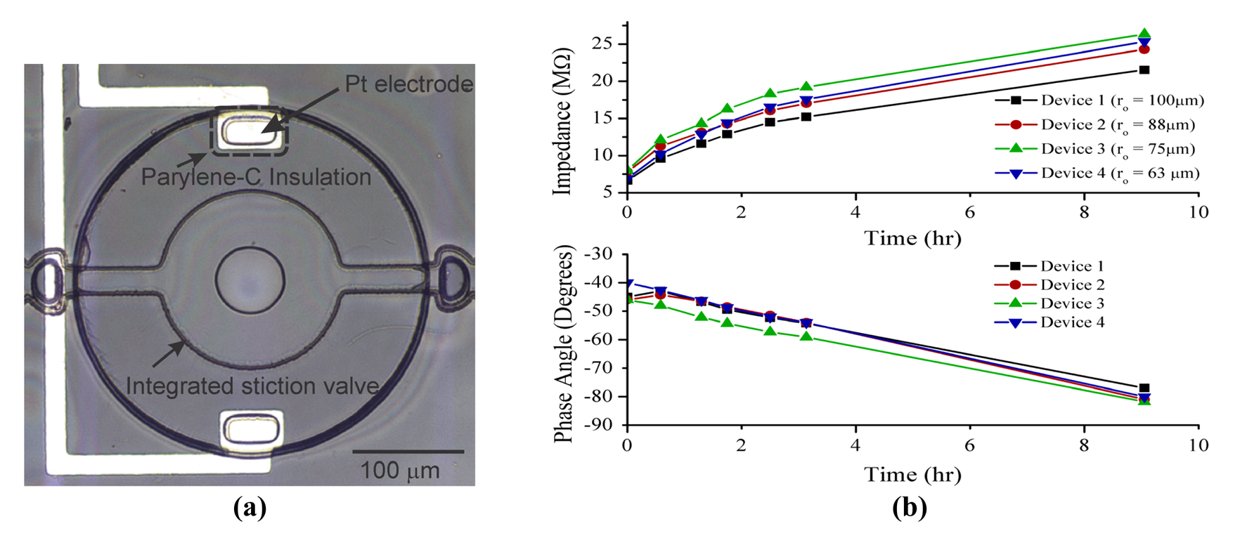
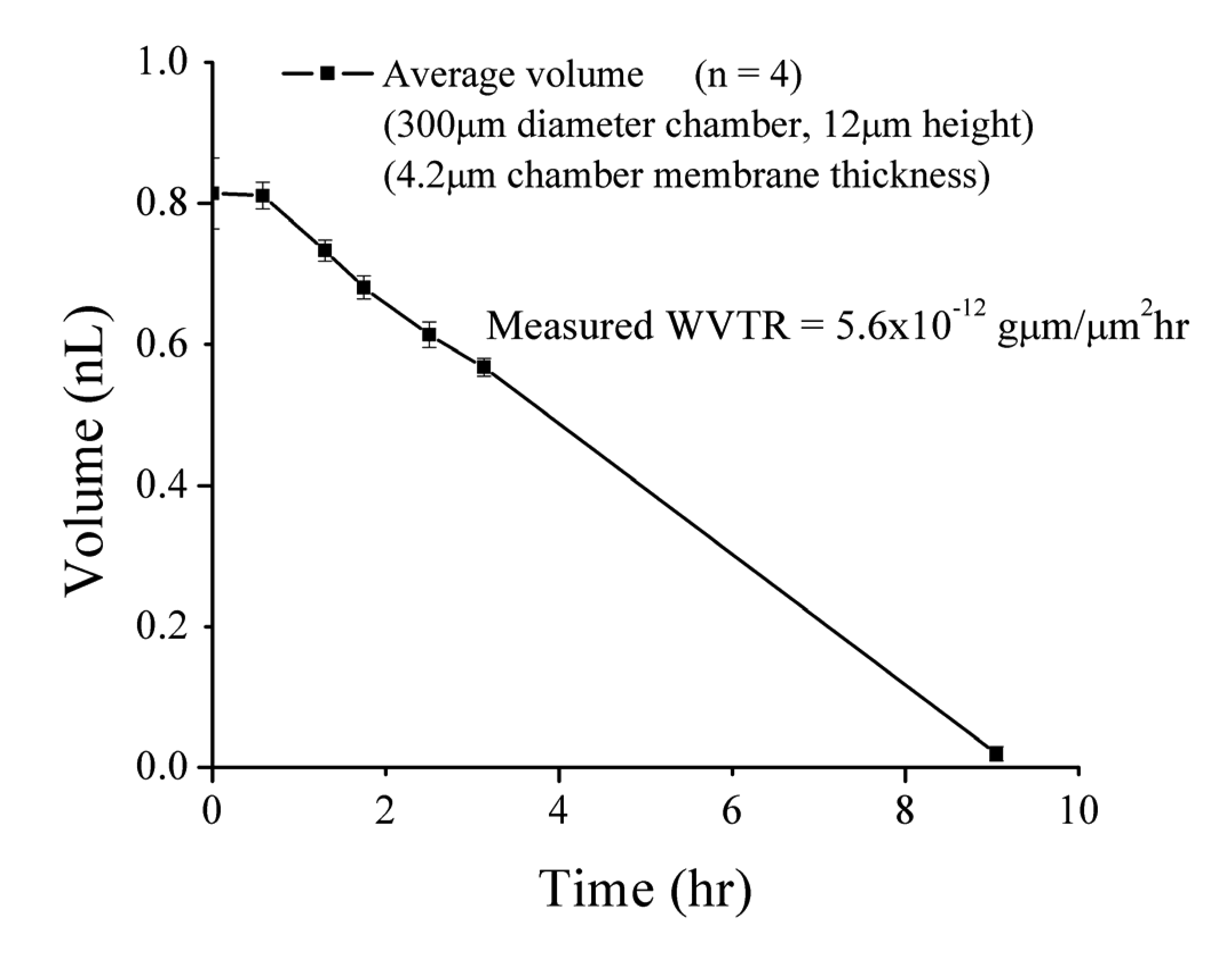
In order to verify that water vapor transmission through the chamber membrane was the primary liquid loss mechanism, four devices were monitored optically under a microscope and electrochemically by solution impedance measurements via the integrated microelectrodes [Figure 7(a)]. Electrochemical impedance of the encapsulated liquid was measured (5 kHz, 100 mVpp) over time using an Agilent precision LCR meter (E4980A, Agilent Inc, Santa Clara, CA, USA). Impedance measurements were consistent across multiple devices and clearly tracked liquid volume changes over time [Figure 7(b)]. By correlating time stamped optical micrographs with measured impedance data, liquid loss was quantitatively tracked and measured (Figure 8). Phase angle measurements clearly followed a linear relationship with volume. As liquid was lost, the phase angle approached −90°, indicating the transition from a mostly resistive phase angle contribution (i.e., solution present) to capacitive (i.e., no solution present).
Four different valve designs were utilized in these experiments to assess the dependence of the stiction seal footprint on sealing performance. Generally for a given set of valve thickness and height, the stiction footprint increased with valve diameter. Although the impedance magnitude data seemed to indicate that that the larger valve diameter produced relatively smaller impedance changes and thus maintained liquid volume somewhat more effectively, there was no significant benefit observed in the phase data. In addition, no significant difference was observed via optical methods. These observations suggest that any potential performance gains of using larger valves versus smaller valves are minimal and that the key requirement for valve sealing remains the initiation of stiction.
The change in liquid volume over time corresponds to a measured water vapor transmission rate (WVTR) of 5.6 × 10⁻¹² g·μm/μm2·h through top surface of the chamber. This value agrees closely with the previously reported WVTR value of 5.78 × 10⁻¹² g·μm/μm2·h (20 °C, 30% RH) for Parylene C films [12]. This result confirms that the liquid loss mechanism is indeed water vapor transmission directly through the Parylene membrane and not the stiction valve seal. Electrochemical impedance measurements provide a simple and reliable method to quantitatively track internal liquid volumes over time.
3.5. Applications
The performance-limiting factor for liquid encapsulation duration is the water vapor transmission rate through as-deposited Parylene films. To further improve performance, additional techniques can be implemented to enhance encapsulation lifetime (hencapsulation). The parameters affecting hencapsulation are identified below:
In addition to water, it is expected that this encapsulation technique is compatible with a variety of other liquids provided that they are volatile (even if only weakly) and that the surface energy density and contact angle for the desired solution is taken into consideration. The energy of Parylene-liquid interface will vary according to the value of these parameters and appropriate design adjustments need to be made to ensure conditions for stiction are preserved. For example, many common organic solutions including acetone, methanol, ethanol, acetic acid and most oils have known surface energy densities ranging 20–30 mJ/m2 at room temperature [13]. Typically these solutions also exhibit much lower contact angles; use of organic solvents such as methanol and acetone are routinely used during cleaning of Parylene and readily wet the surface indicating contact angles close to 0°.
Many common aqueous salt solutions such as KCl, NaCl and Na2SO4 exhibit slightly higher surface energy densities than pure water (73.4, 73.6 and 74.7 mJ/m2 respectively at 1 M) and vary linearly with concentration following the approximate realation γLA= γLAH2O+ MΔγ, where M is molar concentration and Δγ is typically between 1–2 mJ/m2 for most salt solutions. Contact angle values for water on Parylene have been reported throughout the literature but values for other liquids such as acids and liquid metals, to our knowledge, have yet to be reported.
The valve-in-chamber configuration is useful for applications in electrochemical-based transducers such as force and pressure sensors. The capability of small encapsulated liquid volumes to measure contact forces and hydrostatic pressures has been demonstrated with excellent sensitivity [14,15]. Furthermore, electrolysis-based actuation can be fully exploited by this design as increasing chamber pressure further enforces the seal between the valve plate and substrate in contrast to previously reported in-plane designs in which the valve opened at sufficiently high internal pressures [9,11].
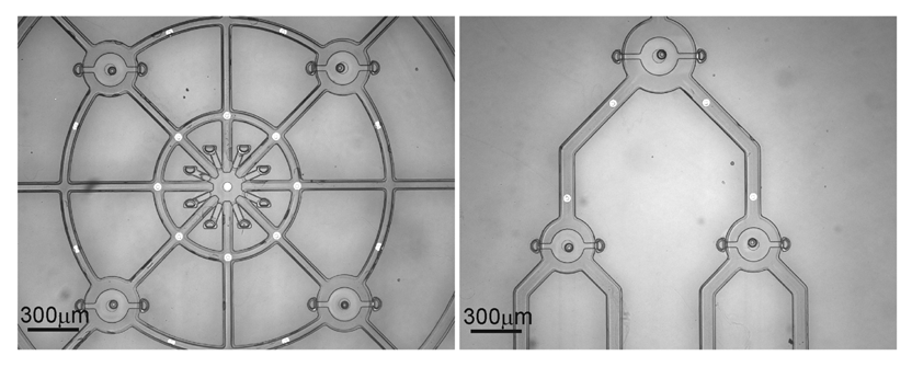
There are numerous applications and configurations for such devices beyond single valve-chamber configurations. Complex interconnected geometries are possible through the use of multiple valves distributed throughout a microfluidic network (Figure 9). This approach reduces to the clearing time of the sacrificial material while still maintaining sealing capability thus allowing for encapsulation within larger structures. The introduction of microelectrodes throughout such structures enables multi-point impedance measurement which has been demonstrated and applied to biomimetic tactile sensing applications at the macroscale [16]. The ability to realize a diverse array of sensor configuration using this liquid encapsulation technology is also potentially useful across a wide array of biomedical applications including tactile feedback for minimally-invasive surgery [17], tissue health diagnostics [18-20], and surgical tool instrumentation [21].
4. Conclusions
The technique utilized here improves encapsulation performance by integrating an optimized stiction valve within a chamber structure. This reduces overall device footprint by nearly 50% over in-plane approaches, extends encapsulation lifetime, is performed in batch at the wafer-level, involves no high temperature or pressure steps and is achieved without adhesives. This is accomplished at the cost of only a few additional standard micromachining processing steps. This improved approach has the potential to enhance many applications where liquid encapsulation is required.


| Dimension (μm) | Design Parameter | Critical Number |
|---|---|---|
| ro/ri | ϕ | Nc |
| 63/20 | 0.32 | 3.14 |
| 75/25 | 0.33 | 6.26 |
| 88/30 | 0.34 | 11.14 |
| 100/35 | 0.35 | 18.23 |
Acknowledgments
This work was funded in part by the Engineering Research Centers Program of the NSF under Award Number EEC-0310723 and the Bill and Melinda Gates Foundation (CG). The authors would like to thank Donghai Zhu and the members of the USC Biomedical Microsystems Laboratory for their assistance.
References
- Khiem, N.B.; Matsumoto, K.; Shimoyama, I. Polymer thin film deposited on liquid for varifocal encapsulated liquid lenses. Appl. Phys. Lett. 2008, 93, 124101. [Google Scholar]
- Lee, J.; Kim, C.-J. Surface-tension-driven microactuation based on continuous electrowetting. J. Microelectromech. Syst. 2000, 9, 171–180. [Google Scholar]
- Matsumoto, S.; Ichikawa, N. New Methods for Liquid Encapsulation in Polymer MEMS Structures. Proceedings of the IEEE 21st International Conference on Micro Electro Mechanical Systems, MEMS 2008, Tucson, AZ, USA, 13–17 January 2008; pp. 415–418.
- Okayama, Y.; Nakahara, K.; Arouette, X.; Ninomiya, T.; Matsumoto, Y.; Orimo, Y.; Hotta, A.; Omiya, M.; Miki, N. Characterization of a bonding-in-liquid technique for liquid encapsulation into MEMS devices. J. Micromech. Microeng. 2010, 20, 095018. [Google Scholar]
- Lapisa, M.A.; Niklaus, F.; Stemme, G. Room-Temperature Wafer-Level Hermetic Sealing for Liquid Reservoirs by Gold Ring Embossing. Proceedings of the International.Solid-State Sensors, Actuators and Microsystems Conference, Transducers 2009, Denver, CO, USA, 21–25 June 2009; pp. 833–836.
- Mastrangelo, C.H.; Hsu, C.H. Mechanical stability and adhesion of microstructures under capillary forces. I. Basic theory. J. Microelectromech. Syst. 1993, 2, 33–43. [Google Scholar]
- Mastrangelo, C.H.; Hsu, C.H. Mechanical stability and adhesion of microstructures under capillary forces. II. Experiments. J. Microelectromech. Syst. 1993, 2, 44–55. [Google Scholar]
- Wang, Z.; Xu, Y. Theoretical and experimental study of annular-plate self-sealing structures. J. Microelectromech. Syst. 2008, 17, 185–192. [Google Scholar]
- Gutierrez, C.A.; Meng, E. A Dual Function Parylene-based Biomimetic Tactile Sensor and Actuator for Next Generation Mechanically Responsive Microelectrode Arrays. Proceedings of the 2009 International SolidState Sensors Actuators and Microsystems Conference, Transducers 2009, Denver, CO, USA, 21–25 June 2009; pp. 2194–2197.
- Gutierrez, C.A.; Meng, E. Improved Self-Sealing Liquid Encapsulation in Parylene Structures by Integrated Stackable Annular-Plate Stiction Valve. Proceedings of the IEEE 23rd International Conference on Micro Electro Mechanical Systems, MEMS 2010, Hong Kong, China, 24–28 January 2010; pp. 524–527.
- Zhang, H.; Wang, S.; Xu, Y. Study and Applications of a Parylene Self-Sealing Structure. Proceedings of the 19th IEEE International Conference on Micro Electro Mechanical Systems, 2006. MEMS 2006, Istanbul, Turkey, 2006; pp. 282–285.
- Menon, P.R.; Li, W.; Tooker, A.; Tai, Y.C. Characterization of Water Vapor Permeation Through Thin Film Parylene C. Proceedings of the International Solid-State Sensors, Actuators and Microsystems Conference, Denver, CO, USA, 21–25 June 2009; pp. 1892–1895.
- Joseph, J.J. The surface tension of pure liquid compounds. J. Phys. Chem. Ref. Data 1972, 1, 841–1010. [Google Scholar]
- Ateya, D.A.; Shah, A.A.; Hua, S.Z. Impedance-based response of an electrolytic gas bubble to pressure in microfluidic channels. Sens. Actuat. A 2005, 122, 235–241. [Google Scholar]
- Gutierrez, C.A.; Meng, E. A Subnanowatt Microbubble Pressure Sensor based on Electrochemical Impedance Transduction in a Flexible All-Parylene Package. Proceedings of the 2011 IEEE 24th International Conference on Micro Electro Mechanical Systems, MEMS 2011, Cancun, Mexico, 23–27 January 2011; pp. 549–552.
- Wettels, N.; Santos, V.J.; Johansson, R.S.; Loeb, G.E. Biomimetic tactile sensor array. Adv. Rob. 2008, 22, 829–849. [Google Scholar]
- Eltaib, M.E.H.; Hewit, J.R. Tactile sensing technology for minimal access surgery—A review. Mechatronics 2003, 13, 1163–1177. [Google Scholar]
- Han, L.; Noble, J.A.; Burcher, M. A novel ultrasound indentation system for measuring biomechanical properties of in vivo soft tissue. Ultrasound Med. Biol. 2003, 29, 813–823. [Google Scholar]
- Plewes, D.B.; Bishop, J.; Samani, A.; Sciarretta, J. Visualization and quantification of breast cancer biomechanical properties with magnetic resonance elastography. Phys. Med. Biol. 2000, 45, 1591–610. [Google Scholar]
- Samani, A.; Bishop, J.; Luginbuhl, C.; Plewes, D.B. Measuring the elastic modulus of ex vivo small tissue samples. Phys. Med. Biol. 2003, 48, 2183–2198. [Google Scholar]
- Tokida, M. Integration of Cell Sheet Sucking and Tactile Sensing Functions to Retinal Pigment Epithelium Transplantation Tool. Proceedings of the IEEE 23rd International Conference on Micro Electro Mechanical Systems, MEMS 2010, Hong Kong, China, 24–28 January 2010; pp. 316–319.
© 2011 by the authors; licensee MDPI, Basel, Switzerland. This article is an open access article distributed under the terms and conditions of the Creative Commons Attribution license (http://creativecommons.org/licenses/by/3.0/).
Share and Cite
Gutierrez, C.A.; Meng, E. Liquid Encapsulation in Parylene Microstructures Using Integrated Annular-Plate Stiction Valves. Micromachines 2011, 2, 356-368. https://doi.org/10.3390/mi2030356
Gutierrez CA, Meng E. Liquid Encapsulation in Parylene Microstructures Using Integrated Annular-Plate Stiction Valves. Micromachines. 2011; 2(3):356-368. https://doi.org/10.3390/mi2030356
Chicago/Turabian StyleGutierrez, Christian A., and Ellis Meng. 2011. "Liquid Encapsulation in Parylene Microstructures Using Integrated Annular-Plate Stiction Valves" Micromachines 2, no. 3: 356-368. https://doi.org/10.3390/mi2030356