Three Cavity Tunable MEMS Fabry Perot Interferometer

Abstract
:1. Introduction
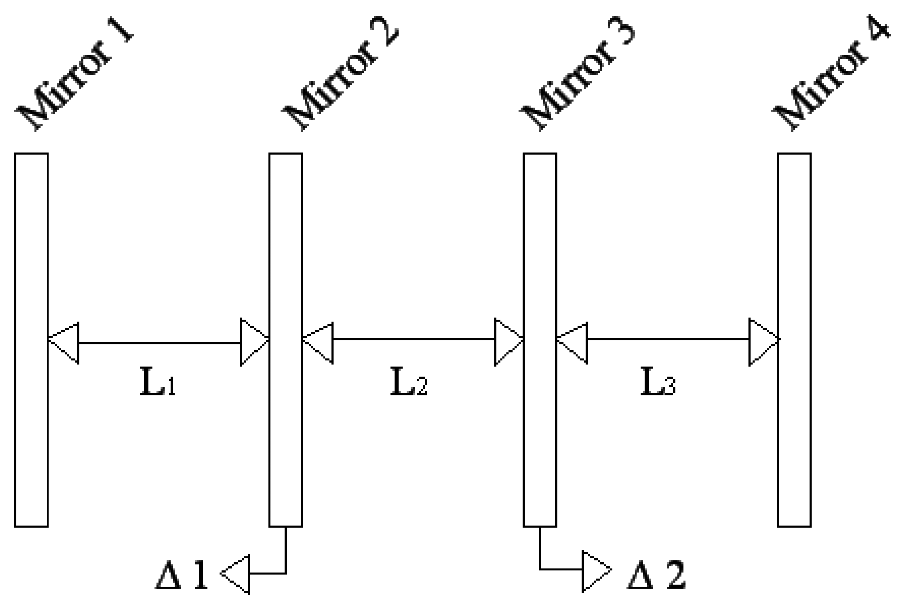
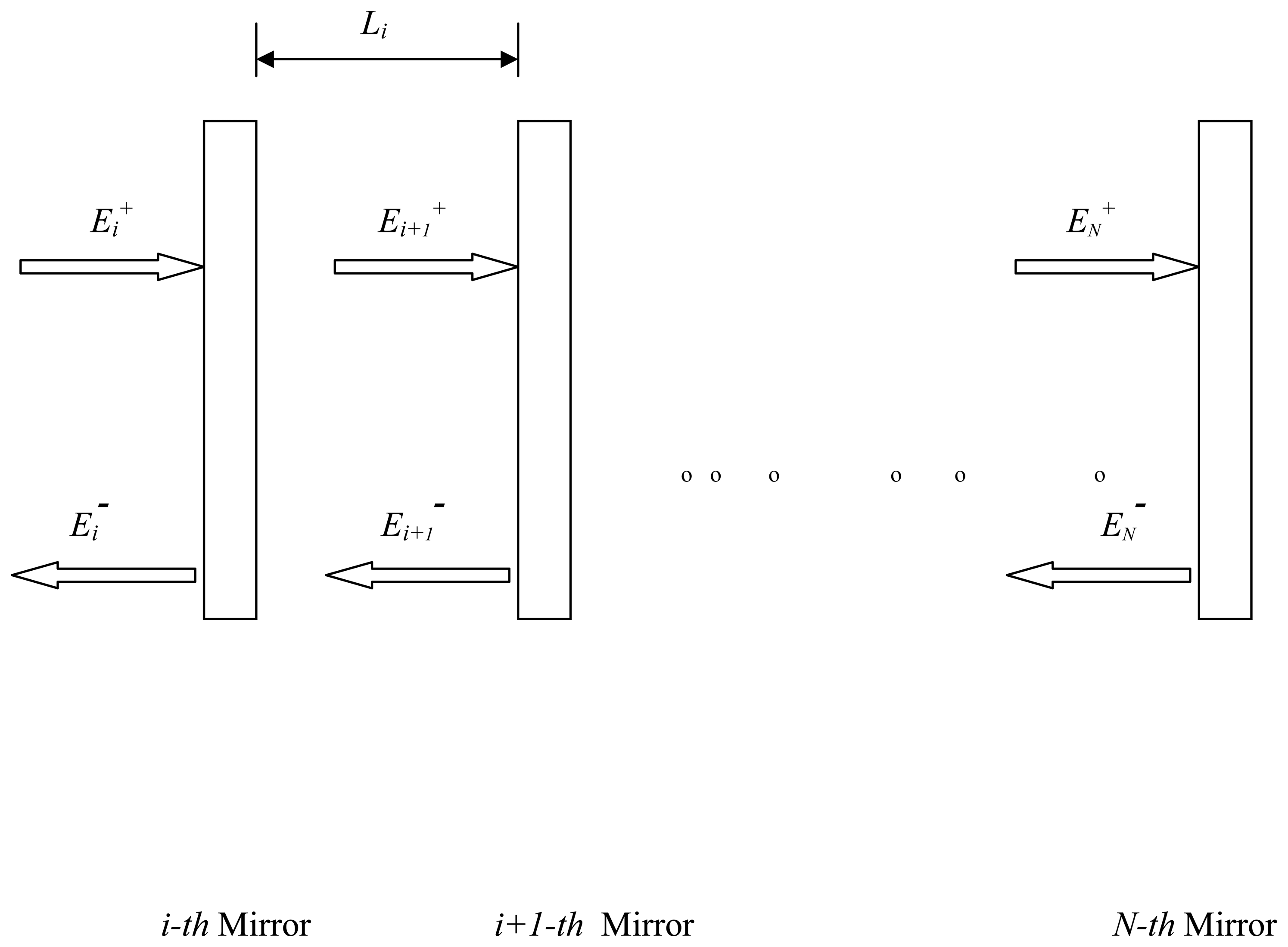
2. Theory
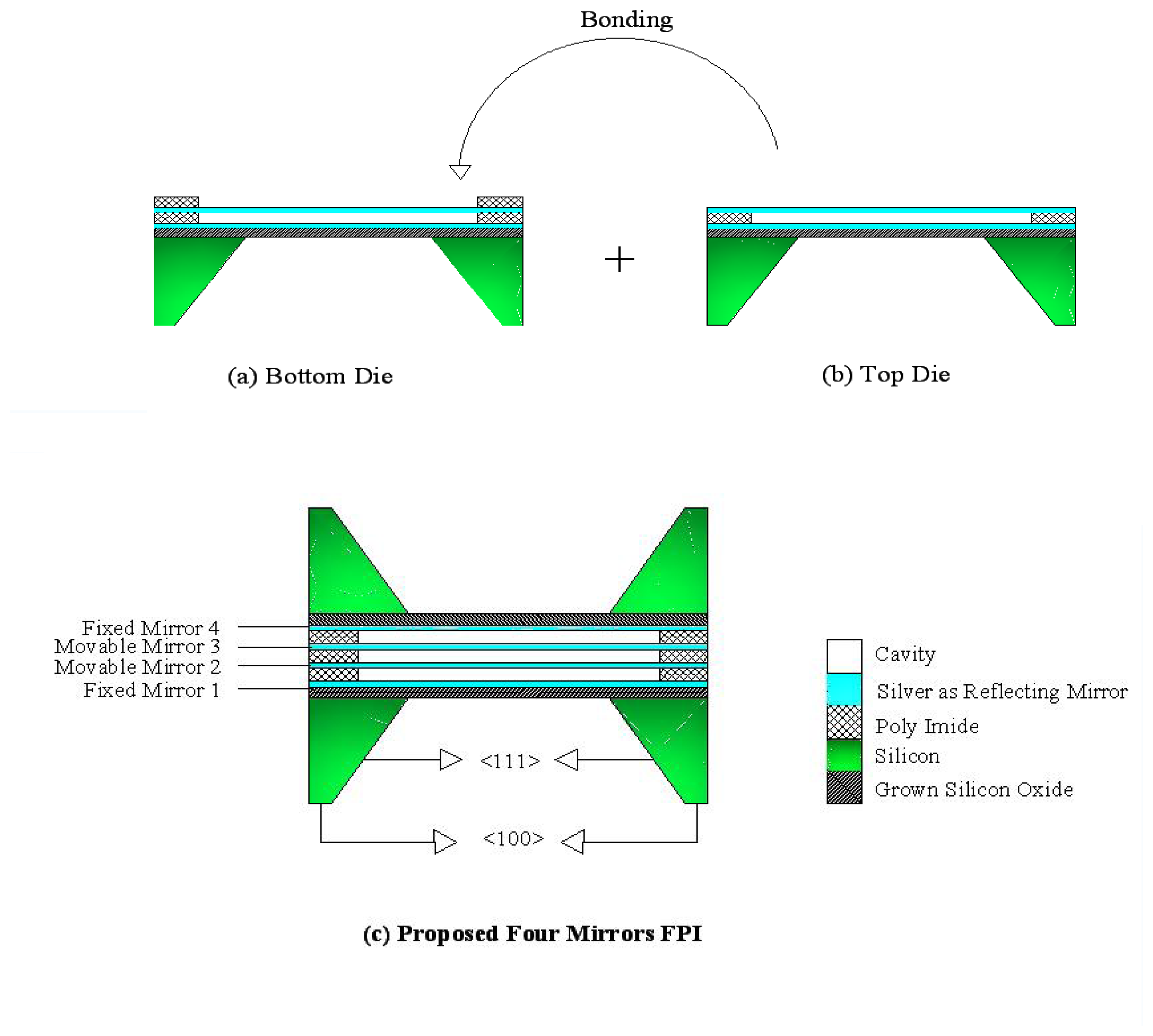
3. Proposed Fabrication Method
4. Analysis
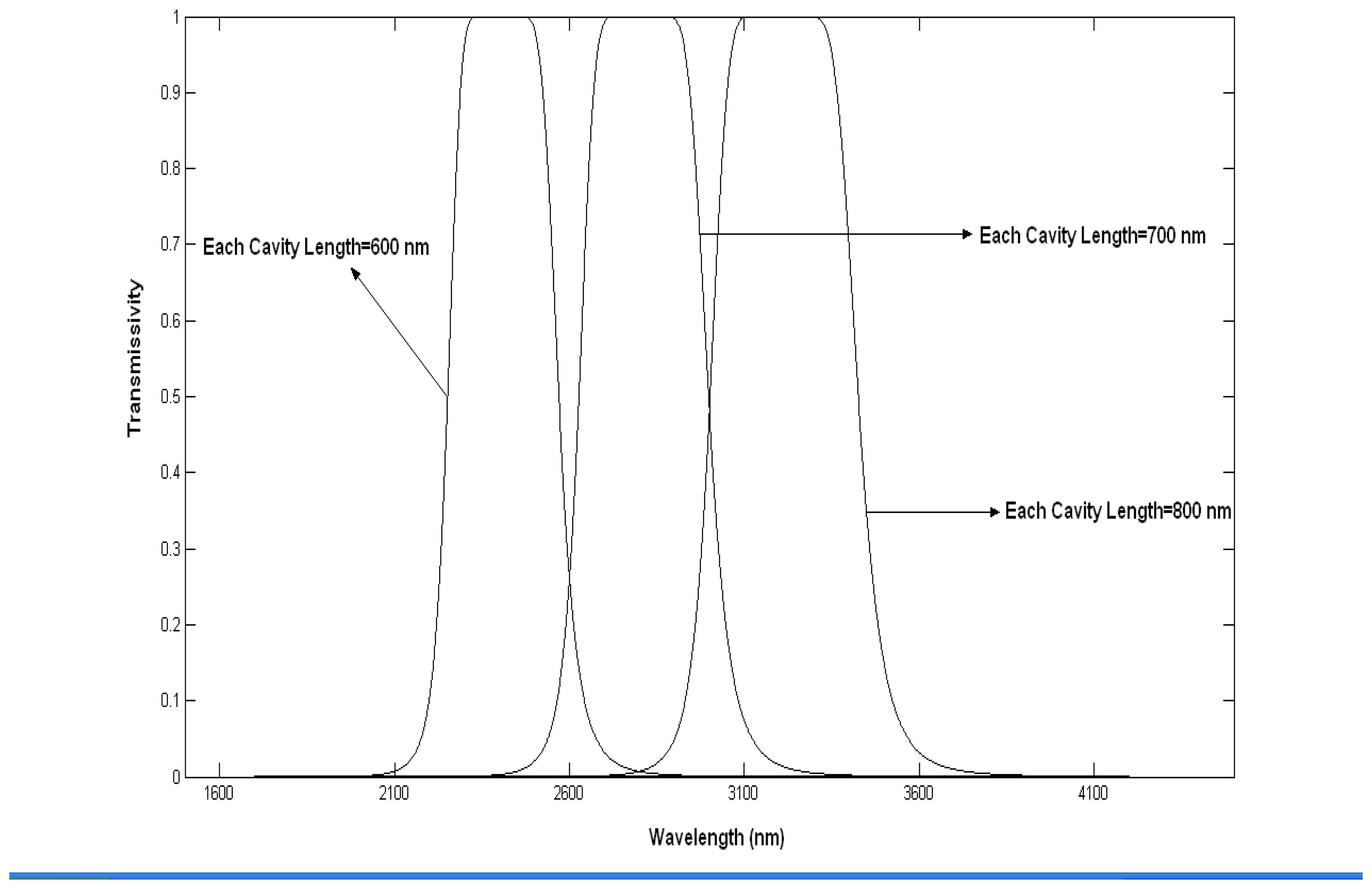
4.1 Fixing of the cavity length
4.2 Case One: (Only one mirror deflection)
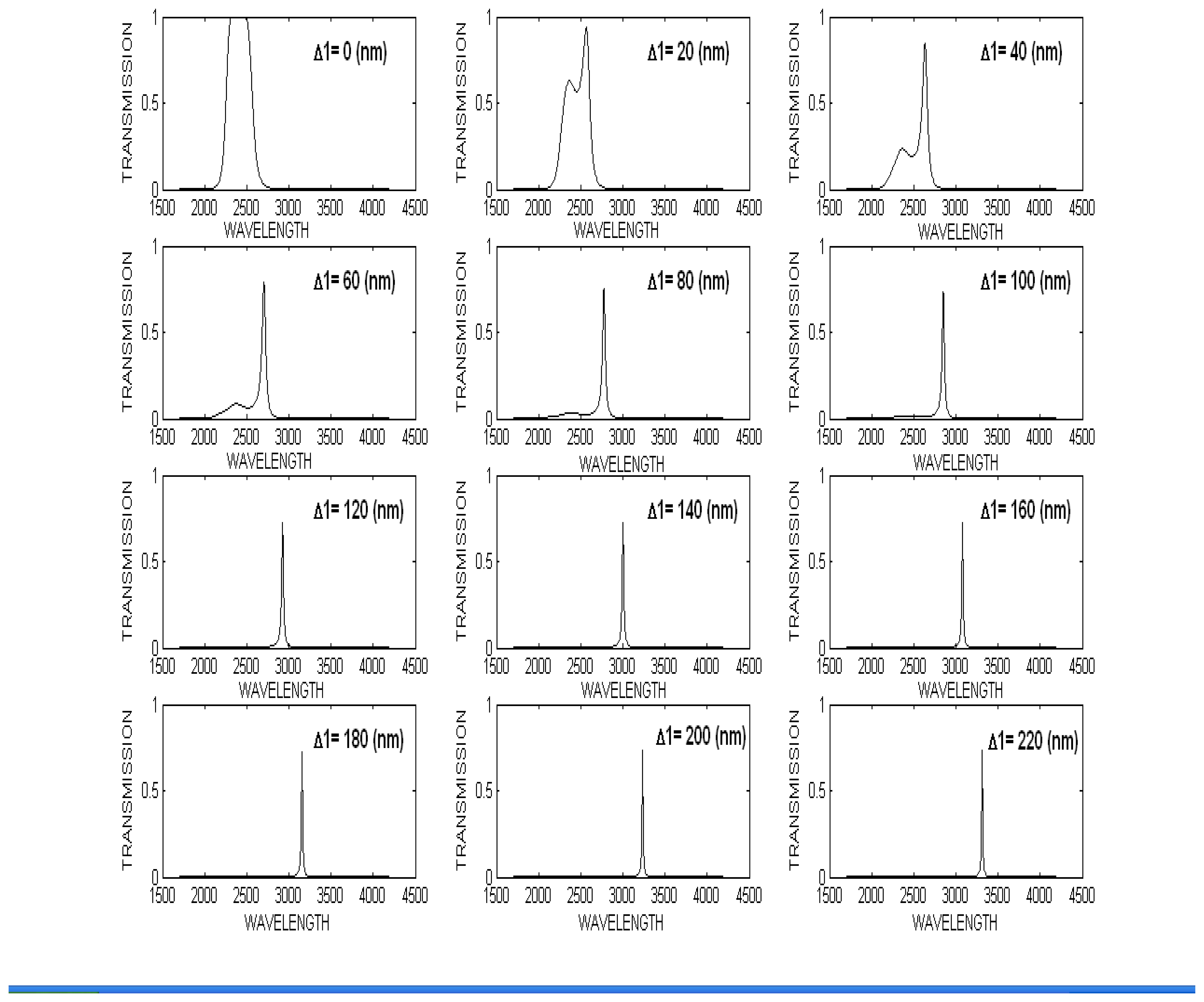
4.2.1 Spectral response in case one: (Only one mirror deflection Δ2=0)
4.3 Case Two: (Both middle mirrors 2 & 3 deflected with equal amount)
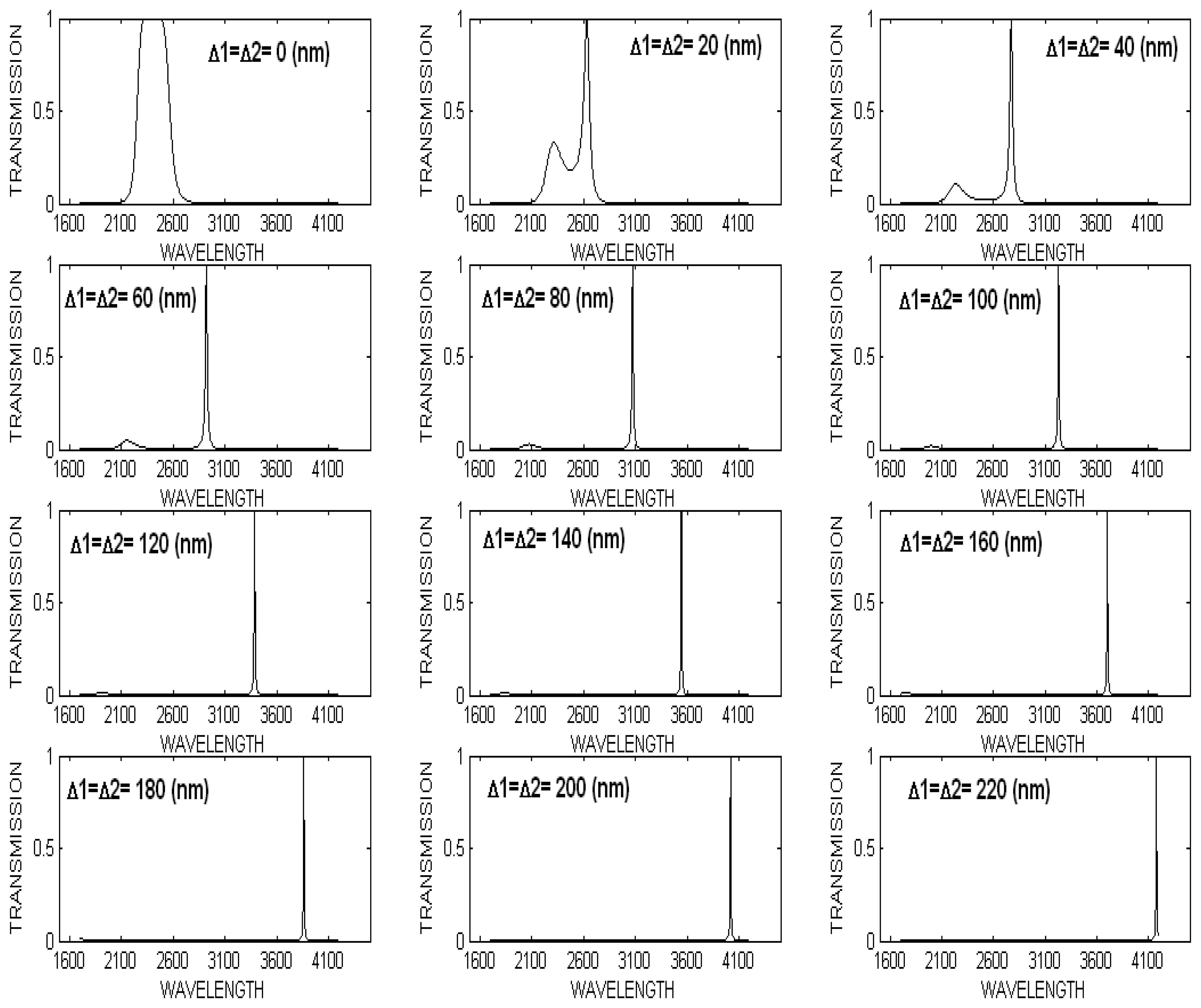
4.3.1 Two middle mirrors were deflected simultaneously for equally deflection (Δ1= Δ2)
4.3.2 Spectral response in case two: (Δ1= Δ2≠0)
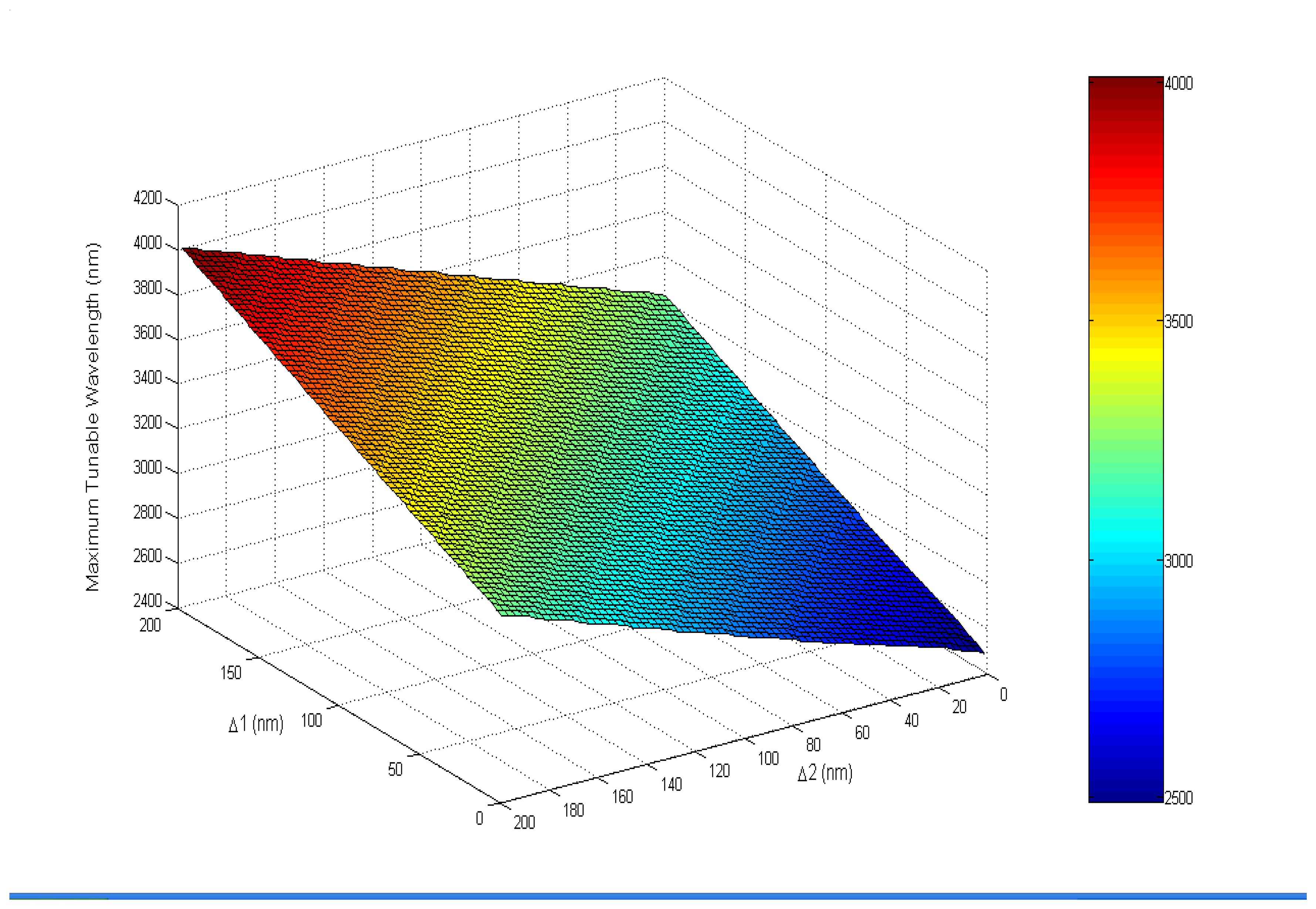
4.3.3 Maximum Tuned wavelength for each deflection
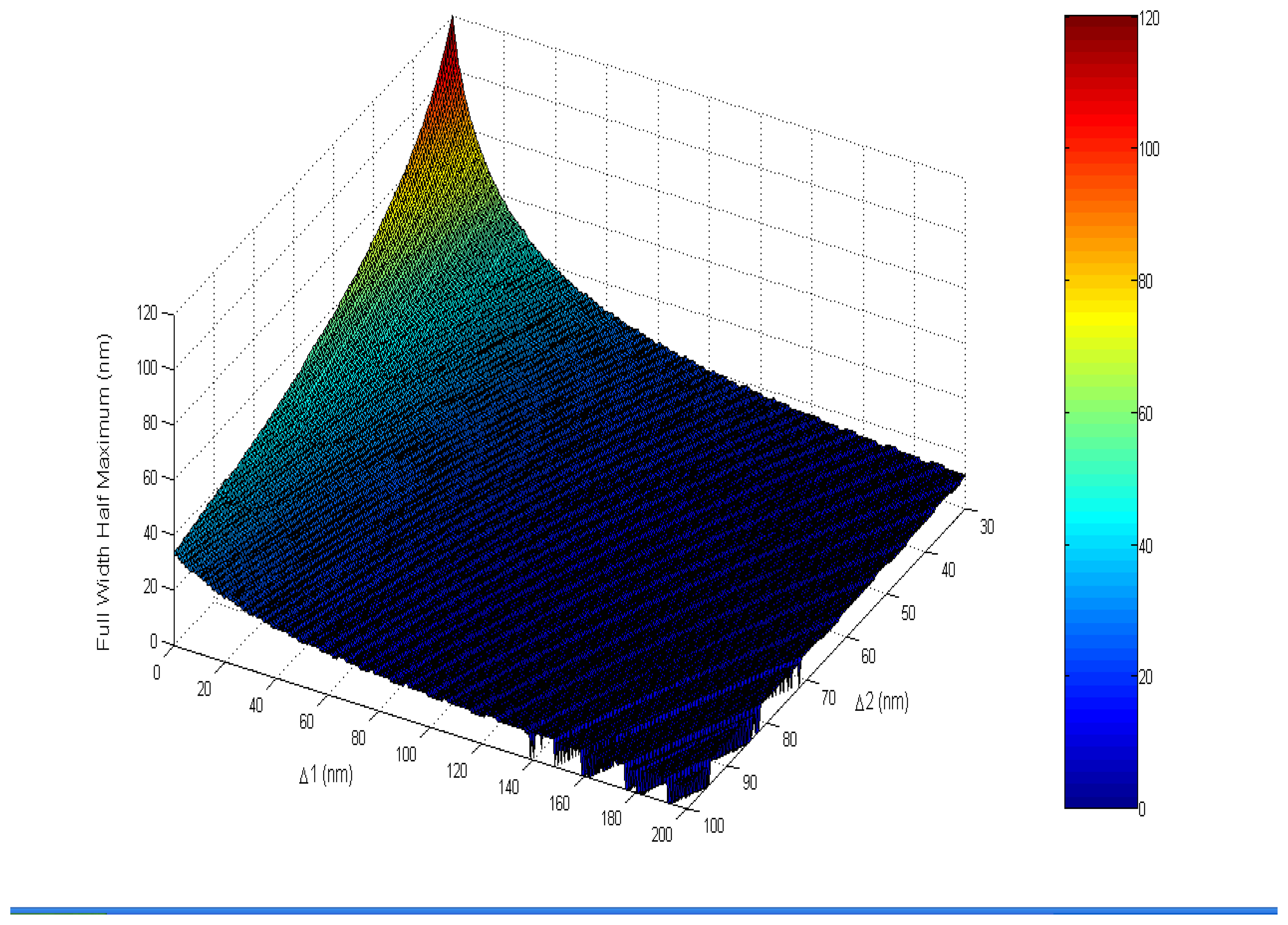
4.3.4 Full Width Half Maximum (FWHM)
5. Conclusion
References
- Onat, B. M.; Masaun, N.; Huang, W.; Lange, M.; Dries, C. Hyperspectral Imaging with MEMs integrated focal plane arrays. Semiconductor Photodetectors II 2005, 5726, 92–102. [Google Scholar]
- Carrano, J.; Brown, J.; Perconti, P.; Barnard, K. Tuning into detection. SPIE Oemagazine 2004, 20–22. [Google Scholar]
- Saari, H.; Mannila, R.; Antila, J.; Blomberg, M.; Rusanen, O.; Tenhunen, J.; Wolf, L.; Harnisch, B. Miniaturised gas sensor using a micromachined Fabry–Pérot interferometer. Preparing for the Future 2000, 10, 4–5. [Google Scholar]
- Kotidis, P.; Atia, W.; Kuznetsov, M.; Fawcett, S.; Nislick, D.; Crocombe, R.; Flanders, D. C. Optical tunable filter-based micro-instrumentation for industrial applications. Proc. Instr. Syst. and Autom. Soc. (ISA) 2003, 1–14. [Google Scholar]
- Keating, A. J.; Silva, K. K.; Dell, J. M.; Musca, C. A.; Faraone, L. Optical Characterization of Fabry-Pérot MEMS Filters Integrated on Tunable Short-Wave IR Detectors. IEEE Photon. Tech. Lett. 2006, 18, 1079–1081. [Google Scholar]
- Hohlfeld, D.; Epmeier, M.; Zappe, H. A thermally tunable Silicon based optical filter. Sensors Actuators A 2003, 103, 93–99. [Google Scholar]
- Aziz, M.; Pfeiffer, J.; Wohlfarth, M.; Luber, C.; Wu, S.; Meissner, P. A new and simple concept of tunable two-chip microcavities for filter applications in WDM systems. IEEE Photon. Tech. Lett. 2000, 12, 1522–1524. [Google Scholar]
- Yun, S.S.; Lee, J.H. A micromachined in plane tunable optical filter using the thermo-optic effect of crystalline silicon. Micromech. Microeng 2003, 721–725. [Google Scholar]
- Meisner, P.; Aziz, M.; Halbritter, H.; Riemenschneider, F.; Pfeiffer, J.; Hermes, T. Micromachined two-chip WDM filters with stable half symmetric cavity and their system integration. Electronic Components and Technology Conference 2002, 52, 34–41. [Google Scholar]
- Loughhead, R. E.; Bray, R. J.; Brown, N. Instrumental profile of a triple Fabry-Perot interferometer for use in solar spectroscopy. Appl. Opt. 1978, 17, 415–419. [Google Scholar]
- Roesler, F. L. Methods of Experimental Physics; Marton, L., Ed.; Academic Press: New York, 1974; Volume 12A, pp. 540–541. [Google Scholar]
- Roychoudhuri, C.; Hercher, M. Stable multipass Fabry-Perotinterferometer: design and analysis. Appl. Opt. 1977, 16, 2514–2520. [Google Scholar]
- Ramsay, J. V.; Kobler, H.; Mugridge, E. G. V. A new tunable filter with a very narrow pass band. Solar Phys. 1970, 12, 492–501. [Google Scholar]
- Bray, R. J. Computer controlled narrow band optical filters in solar astronomy. Radiopyysics and Quantum Electronics 1977, 20, 1318–1330. [Google Scholar]
- Ellis, D. I.; Goodacre, R. Metabolic fingerprinting in disease diagnosis: biomedical applications of infrared and Raman spectroscopy. Analyst 2006, 131, 875–885. [Google Scholar]
- van de Stadt, H.; Muller, J. M. Multimirror Fabry Perot Interferometer. Opt. Soc. Am. A 1985, 2, 1363–1370. [Google Scholar]
- MacLeod, H. A. Thin Film Optical Filters; Hilger: London, U.K., 1969; pp. 303–320. [Google Scholar]
- Born, M.; Wolf, E. Principles of Optics; Pergamon: Oxford, U.K., 1970; pp. 366–368. [Google Scholar]
- Packirisamy, M. Microfabrication Influence on the Behavior of Capacitive Type MEMS Sensors and Actuators. Sensor Review 2006, 26, 58–65. [Google Scholar]


© 2007 by MDPI ( http://www.mdpi.org). Reproduction is permitted for noncommercial purposes.
Share and Cite
Parashar, A.; Shah, A.; Packirisamy, M.; Sivakumar, N. Three Cavity Tunable MEMS Fabry Perot Interferometer. Sensors 2007, 7, 3071-3083. https://doi.org/10.3390/s7123071
Parashar A, Shah A, Packirisamy M, Sivakumar N. Three Cavity Tunable MEMS Fabry Perot Interferometer. Sensors. 2007; 7(12):3071-3083. https://doi.org/10.3390/s7123071
Chicago/Turabian StyleParashar, Avinash, Ankur Shah, Muthukumaran Packirisamy, and Narayanswamy Sivakumar. 2007. "Three Cavity Tunable MEMS Fabry Perot Interferometer" Sensors 7, no. 12: 3071-3083. https://doi.org/10.3390/s7123071
APA StyleParashar, A., Shah, A., Packirisamy, M., & Sivakumar, N. (2007). Three Cavity Tunable MEMS Fabry Perot Interferometer. Sensors, 7(12), 3071-3083. https://doi.org/10.3390/s7123071