
Performance Analysis of the Ironless Inductive Position Sensor in the Large Hadron Collider Collimators Environment

Abstract
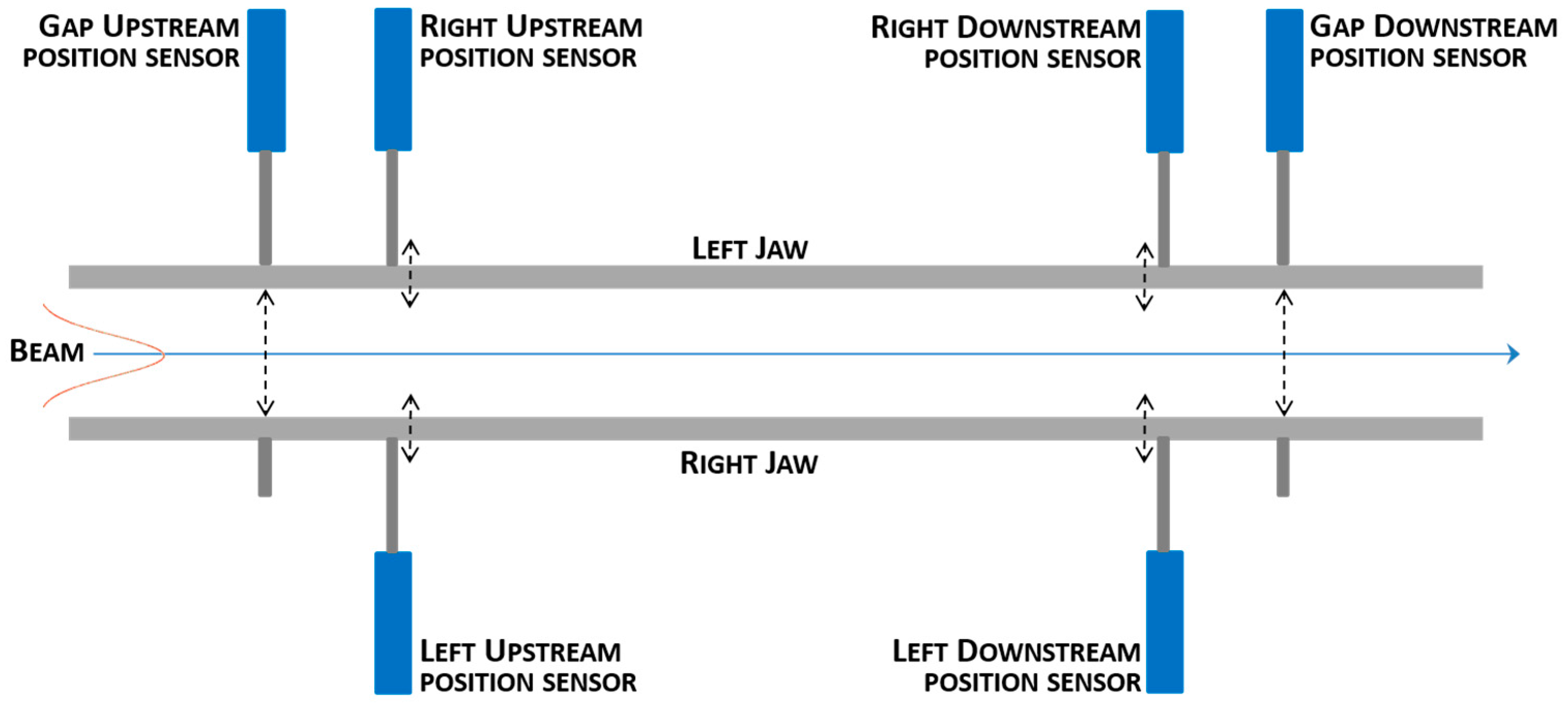
:1. Introduction
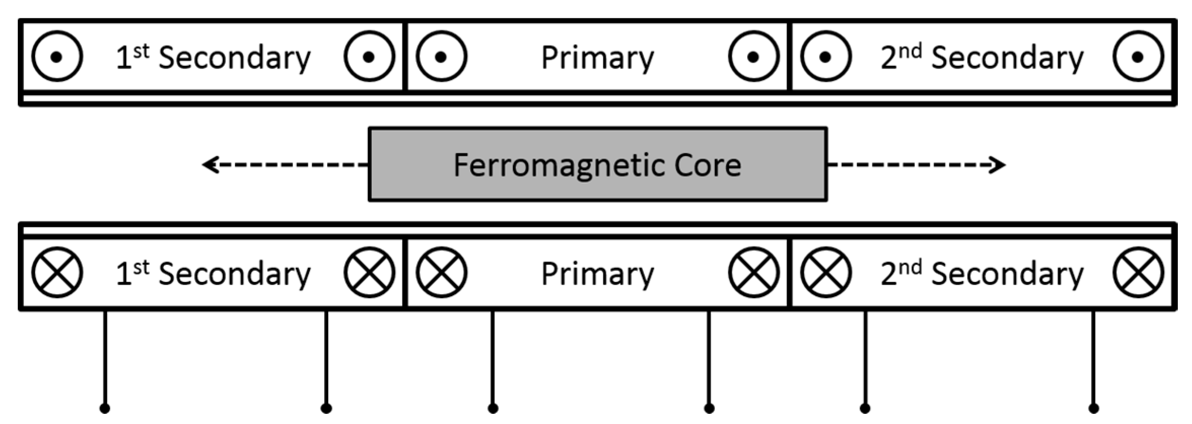
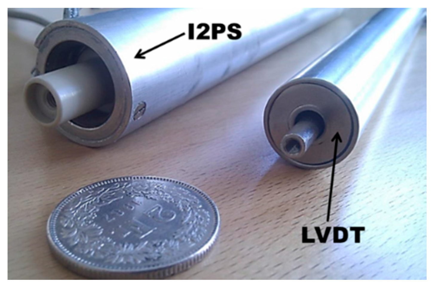
2. The Ironless Inductive Position Sensor (I2PS)


| Feature | LVDT | I2PS |
|---|---|---|
| Working Principle | Inductive | Inductive |
| Supply amplitude range | 2–5 V | 10–50 mA |
| Sensing voltage amplitude | ~3–5 V | ~7–10 V |
| Frequency range | 1–5 kHz | 1–5 kHz |
| Stroke range | ±30 mm | ±30 mm |
| Dimensions | Diameter: 21 mm, Length: 210 mm | Diameter: 27 mm, Length: 230 mm |
| Materials | Ni-Fe alloy, copper (coils), magnetic steel. | Plastics, copper (coils), non-magnetic steel. |
3. The I2PS Network
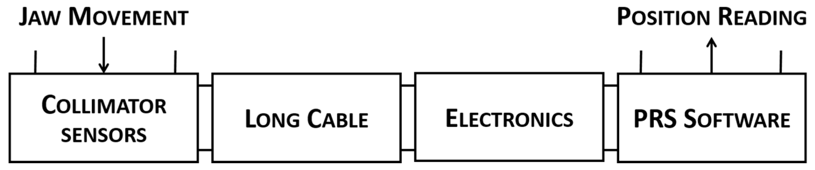
3.1. Control System Architecture
3.2. I2PS Integration

4. Analysis of Sensor Performance
4.1. Position Uncertainty
| Sensor | Type | Standard Deviation/µm | Position Uncertainty/µm |
|---|---|---|---|
| 1 | LVDT | 0.3 | ±0.6 |
| 2 | LVDT | 0.5 | ±1.0 |
| 3 | I2PS | 0.7 | ±1.4 |
| 4 | LVDT | 0.6 | ±1.2 |
| 5 | I2PS | 0.9 | ±1.8 |
| 6 | LVDT | 0.4 | ±0.8 |
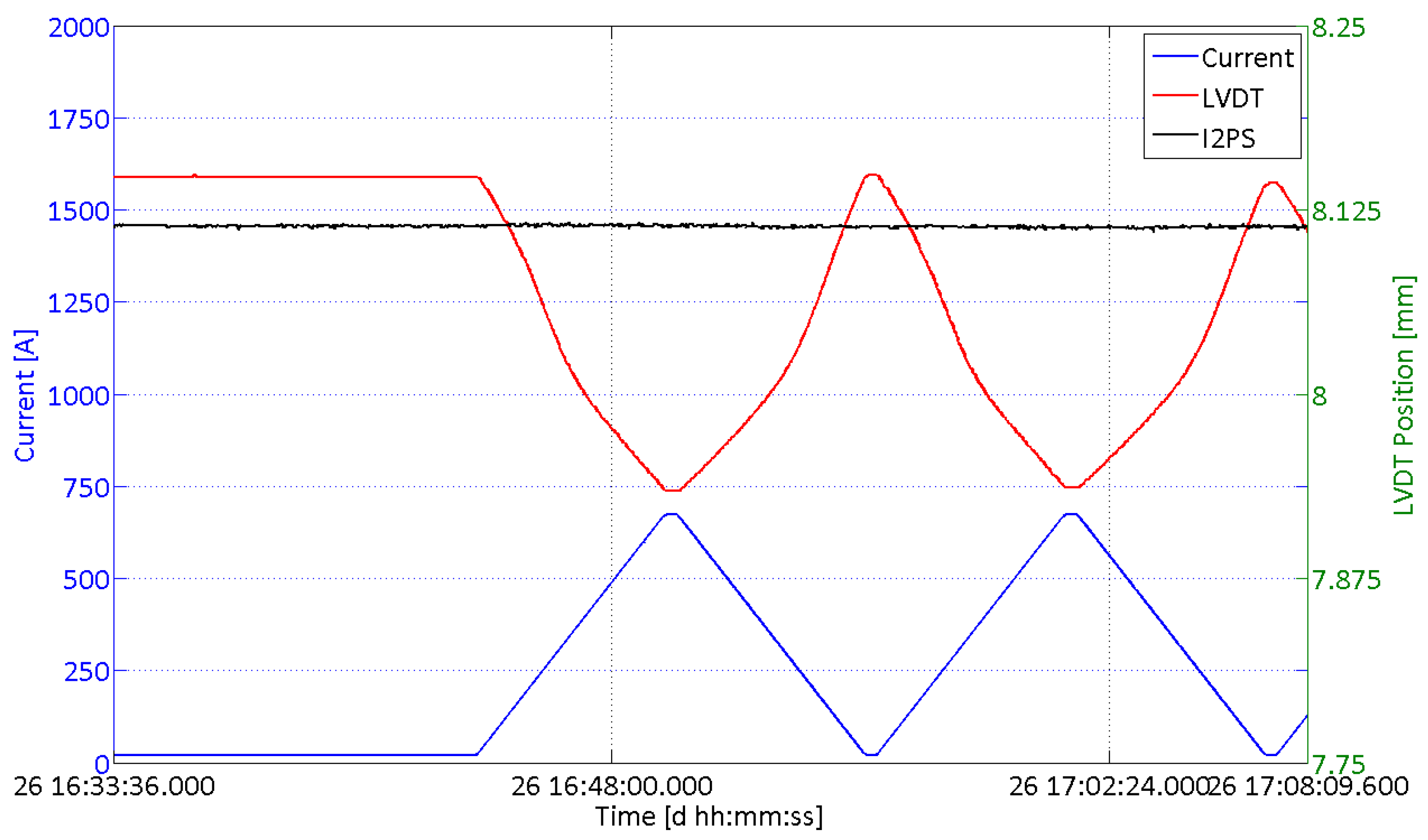
4.2. Magnetic Immunity
4.3. Long-term Stability
| Collimator | Cable Length (m) | Long-term Standard Deviation (µm) | |
|---|---|---|---|
| LVDT | I2PS | ||
| 1 | 180 | 2 | 3 |
| 2 | 293 | 5 | 7 |
| 3 | 380 | 7 | 9.5 |
| 4 | 452 | 3 | 20 |
| 5 | 569 | 10 | 25 |
5. Conclusions and Outlook
Acknowledgments
Author Contributions
Conflicts of Interest
References
- Bruning, O.S.; Collier, P.; Lebrun, P.; Myers, S.; Ostojic, R.; Poole, J.; Proudlock, P. LHC Design Report; CERN—European Organization for Nuclear Research: Geneva, Switzerland, 2004. [Google Scholar]
- Redaelli, S.; Assmann, R.; Gander, P.; Jonker, M.; Lamont, M.; Losito, R.; Masi, A.; Sobczak, M. The LHC Collimators Controls Architecture—Design and Beam Tests. In Proceedings of the Particle Accelerator Conference, Albuquerque, NM, USA, 25–29 June 2007; pp. 344–346.
- Weiler, T.; Aberle, O.; Assman, R.; Chamizo, R.; Kadi, Y.; Lettry, J.; Losito, R.; Redaelli, S. LHC Collimation System Hardware Commissioning. In Proceedings of the Particle Accelerator Conference, Albuquerque, NM, USA, 25–29 June 2007; pp. 1625–1627.
- Masi, A.; Losito, R. LHC collimators low level control system. IEEE Trans. Nucl. Sci. 2008, 55, 333–340. [Google Scholar] [CrossRef]
- Masi, A.; Butcher, M.; Losito, R.; Picatoste, R. DSP based smart sensorless stepping motor driver for LHC collimators. IEEE Trans. Nucl. Sci. 2013, 60, 3514–3520. [Google Scholar] [CrossRef]
- Danisi, A. Simulation of DC Interfering Magnetic Field Effects on the LHC Collimators, LVDT Positioning Sensors. M.Sc. Thesis, University of Naples “Federico II”, Naples, Italy, 2009. [Google Scholar]
- Fernandez, A.F.; Berghmans, F.; Brichard, B.; Decreton, M. Toward the development of radiation-tolerant instrumentation data links for thermonuclear fusion experiments. IEEE Trans. Nucl. Sci. 2002, 49, 2879–2887. [Google Scholar] [CrossRef]
- Masi, A.; Brielmann, A.; Losito, R.; Martino, M. LVDT conditioning on the LHC collimators. IEEE Trans. Nucl. Sci. 2008, 55, 67–85. [Google Scholar] [CrossRef]
- Shaevitz® LVDTs Provides Rugged Position Sensing for Super Collider—Ultra-precision LVDT Measurement in Extremely Challenging Conditions. Available online: http://meas-spec.com.cn/downloads/Position_Sensing_for_CERN_Super_Collider.pdf (accessed on 6 November 2015).
- Eren, H. Inductive Displacement Sensors. In The Measurement, Instrumentation and Sensors Handbook, 10th ed.; CRC Press: Boca Raton, FL, USA, 1999; pp. 6.26–6.32. [Google Scholar]
- Fraden, J. Handbook of Modern Sensors: Physics, Designs, and Applications, 3rd ed.; AIP Press: New York, NY, USA, 2004. [Google Scholar]
- Martino, M.; Danisi, A.; Losito, R.; Masi, A.; Spiezia, G. Design of a LVDT with high rejection to external interfering magnetic field. IEEE Trans. Magn. 2010, 46, 674–677. [Google Scholar] [CrossRef]
- Masi, A.; Danisi, A.; Losito, R.; Spiezia, G. Study of magnetic interference on an LVDT: Fem modeling and experimental measurements. J. Sens. 2011, 2011. [Google Scholar] [CrossRef]
- Spiezia, G.; Losito, R.; Martino, M.; Masi, A.; Pierno, A. Automatic test bench for measurement of magnetic interference on LVDTs. IEEE Trans. Instrum. Meas. 2010, 60, 1802–1810. [Google Scholar] [CrossRef]
- Danisi, A.; Masi, A.; Losito, R.; Perriard, Y. Electromagnetic analysis and validation of an ironless inductive position sensor. IEEE Trans. Instrum. Meas. 2013, 62, 1267–1275. [Google Scholar] [CrossRef]
- Danisi, A.; Masi, A.; Losito, R.; Perriard, Y. Modeling of high-frequency electromagnetic effects on an ironless inductive position sensor. IEEE Sens. J. 2013, 13, 4663–4670. [Google Scholar] [CrossRef]
- Masi, A.; Danisi, A.; Castro, M.D.; Losito, R. Real-time high-precision reading algorithm for the ironless inductive position sensor. IEEE Trans. Nucl. Sci. 2013, 60, 3661–3668. [Google Scholar] [CrossRef]
- Danisi, A.; Masi, A.; Losito, R.; Perriard, Y. Modeling and compensation of thermal effects on an ironless inductive position sensor. IEEE Trans. Ind. Appl. 2014, 50, 375–382. [Google Scholar] [CrossRef]
- Danisi, A.; Masi, A.; Losito, R.; Perriard, Y. Design optimization of an ironless inductive position sensor for the LHC collimators. J. Inst. 2013, 8. [Google Scholar] [CrossRef]
- Nyce, D.S. Magnetic Displacement Sensors. In The Measurement, Instrumentation and Sensors Handbook, 10th ed.; CRC Press: Boca Raton, FL, USA, 1999. [Google Scholar]
- Ara, K. A differential transformer with temperature-and excitation-independent output. IEEE Trans. Instrum. Meas. 1972, 21, 249–255. [Google Scholar] [CrossRef]
- Danisi, A. Ironless Inductive Position Sensor for Harsh Magnetic Environments. Ph.D. Thesis, École Polytechnique Fédérale de Lausanne, Lausanne, Switzerland, 2013. [Google Scholar]
- Martino, M.; Golluccio, G.; Losito, R.; Masi, A. An analytical model of the effect of external DC magnetic fields on the ac voltages of an LVDT. In Proceedings of the IEEE Instrumentation and Measurement Technology Conference, Austin, TX, USA, 3–6 May 2010; pp. 213–218.
- Bozorth, R. Concepts of Ferromagnetism. In Ferromagnetism, 3rd ed.; D. Van Nostrand Company: New York, NY, USA, 1951; pp. 1–14. [Google Scholar]
- Nyce, D.S. Linear Position Sensors; Wiley-Interscience: Hoboken, NJ, USA, 2004. [Google Scholar]
- Bozorth, R. Iron-Nickel Alloys. In Ferromagnetism, 3rd ed.; D. Van Nostrand Company: New York, NY, USA, 1951. [Google Scholar]
- Megusar, J. Low temperature fast-neutron and gamma irradiation of kapton® polyimide films. J. Nucl. Mater. 1997, 245, 185–190. [Google Scholar] [CrossRef]
- Danisi, A.; Losito, R.; Masi, A. Impact evaluation of environmental and geometrical parasitic effects on high-precision position measurement of the LHC collimator jaws. Meas. Sci. Technol. 2015, 26. [Google Scholar] [CrossRef]
© 2015 by the authors; licensee MDPI, Basel, Switzerland. This article is an open access article distributed under the terms and conditions of the Creative Commons Attribution license (http://creativecommons.org/licenses/by/4.0/).
Share and Cite
Danisi, A.; Masi, A.; Losito, R. Performance Analysis of the Ironless Inductive Position Sensor in the Large Hadron Collider Collimators Environment. Sensors 2015, 15, 28592-28602. https://doi.org/10.3390/s151128592
Danisi A, Masi A, Losito R. Performance Analysis of the Ironless Inductive Position Sensor in the Large Hadron Collider Collimators Environment. Sensors. 2015; 15(11):28592-28602. https://doi.org/10.3390/s151128592
Chicago/Turabian StyleDanisi, Alessandro, Alessandro Masi, and Roberto Losito. 2015. "Performance Analysis of the Ironless Inductive Position Sensor in the Large Hadron Collider Collimators Environment" Sensors 15, no. 11: 28592-28602. https://doi.org/10.3390/s151128592
APA StyleDanisi, A., Masi, A., & Losito, R. (2015). Performance Analysis of the Ironless Inductive Position Sensor in the Large Hadron Collider Collimators Environment. Sensors, 15(11), 28592-28602. https://doi.org/10.3390/s151128592