
On Improving Reliability of SRAM-Based Physically Unclonable Functions

Abstract
:1. Introduction
2. Background
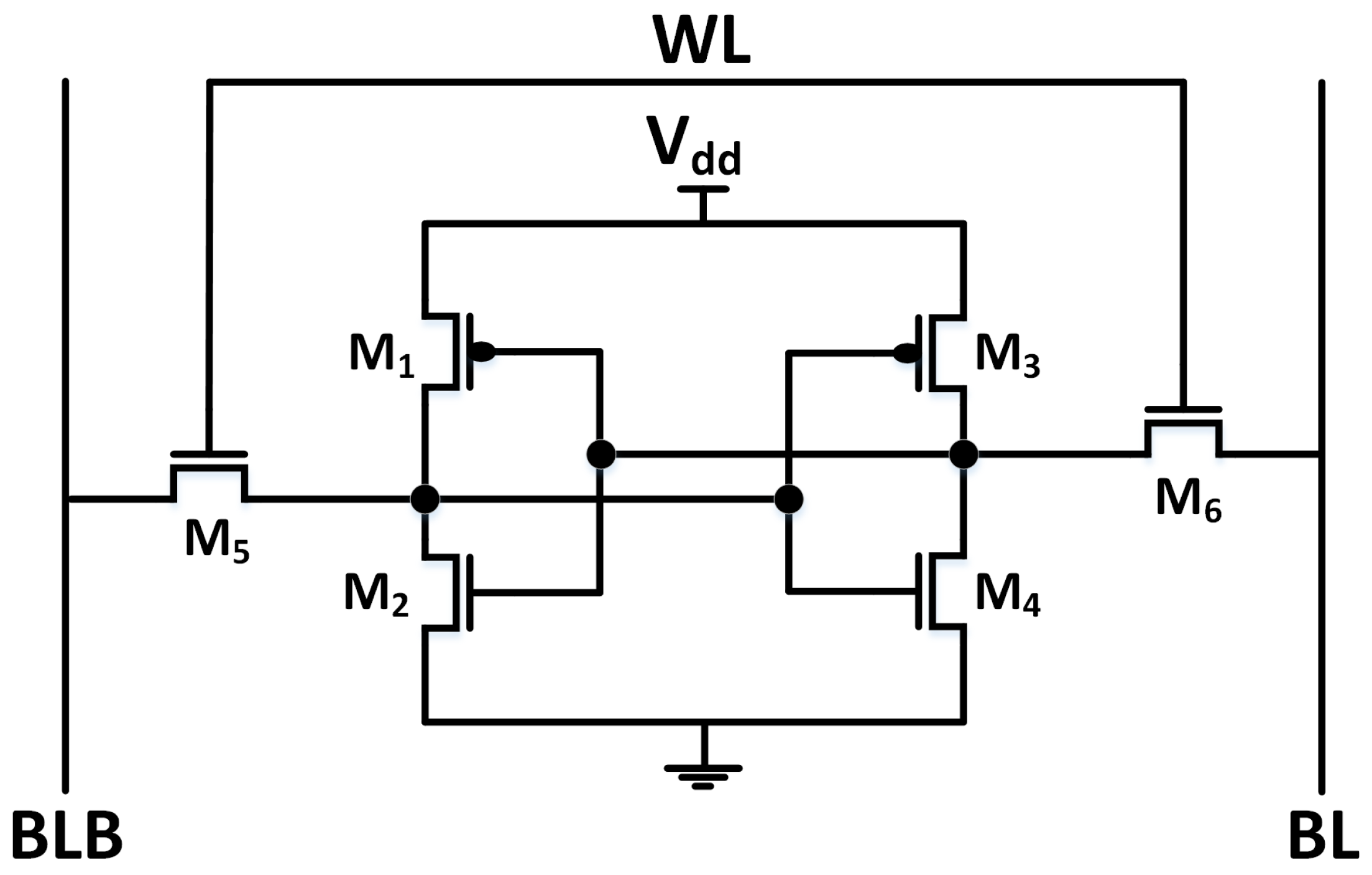
2.1. SRAM PUF and Reliability
2.2. Related Literature
2.2.1. Error-Correcting Codes and Fuzzy Extractor
2.2.2. Circuit and Manufacturing Technology Solutions
3. Proposed Technique
3.1. Harnessing Statistical Bias for Improving Reliability
3.2. Temporal Majority Voting
3.3. New Voter Design
3.4. Circuit Design
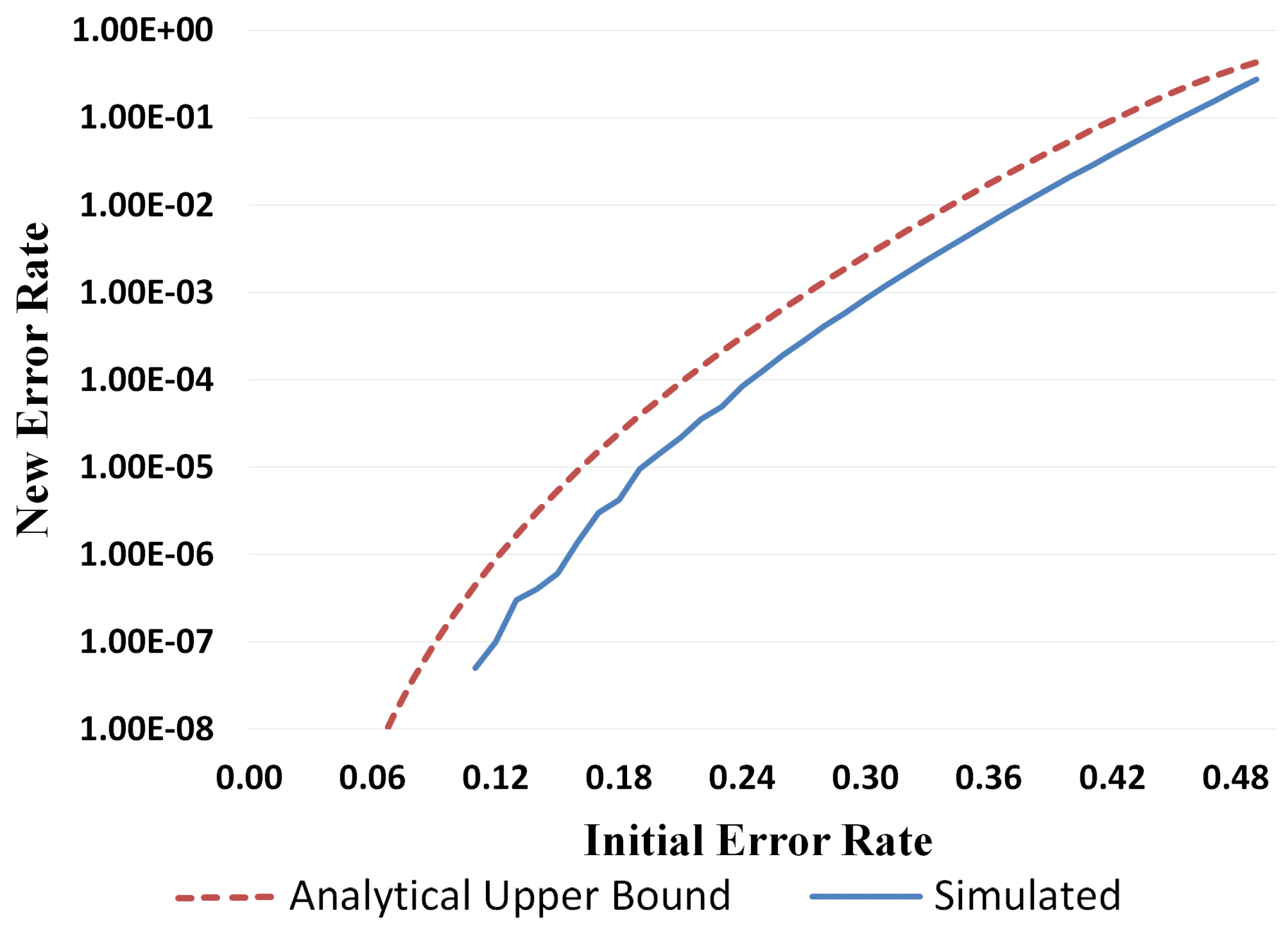
3.5. Error Rate from Simulation
4. Analysis of the Proposed Counter Based Design
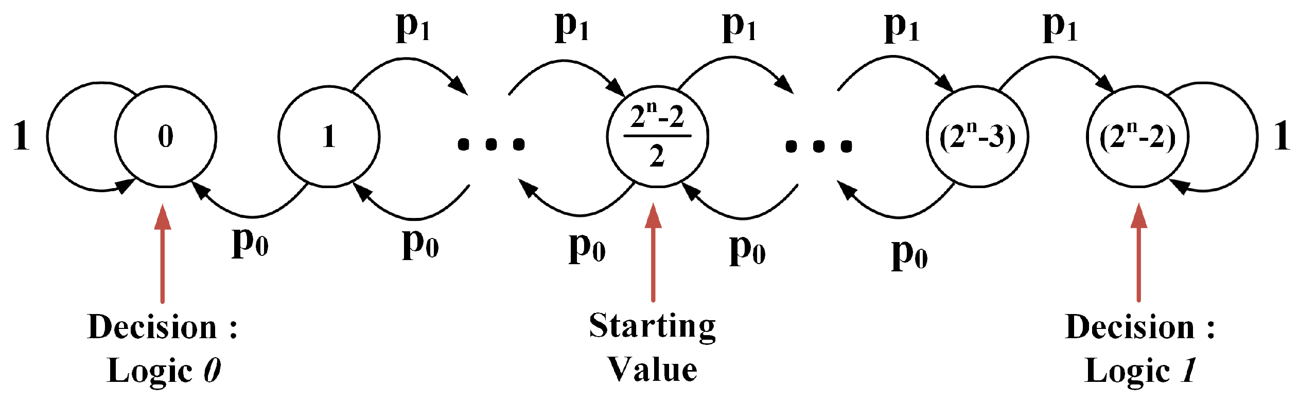
4.1. Operation of the Proposed Voter as Random Walk
4.2. Error Rate
4.3. UP/DOWN Counter vs. TMV
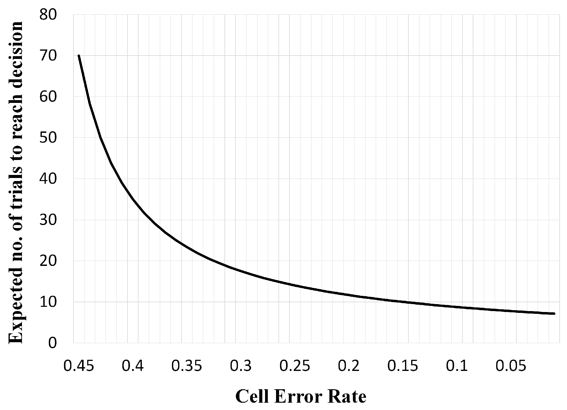
4.4. DFT Based on Trials to Settlement
5. Results and Case Studies
5.1. Case Study: Redundancy to Improve Yield and Reduce Error Rate
5.2. Design Area/Performance Comparisons
6. Conclusions
Acknowledgments
Author Contributions
Conflicts of Interest
References
- Gassend, B.; Clarke, D.; van Dijk, M.; Devadas, S. Silicon physical random functions. In Proceedings of the 9th ACM Conference on Computer and Communications Security, Washington, DC, USA, 18–22 November 2002; pp. 148–160.
- Rührmair, U.; Sölter, J.; Sehnke, F. On the foundations of physical unclonable functions. IACR Cryptol. ePrint Arch. 2009, 2009, 277. [Google Scholar]
- Maes, R.; Verbauwhede, I. Physically unclonable functions: A study on the state of the art and future research directions. In Towards Hardware-Intrinsic Security; Sadeghi, A.R., Naccache, D., Eds.; Information Security and Cryptography; Springer: Berlin/Heidelberg, Germany, 2010; pp. 3–37. [Google Scholar]
- Guajardo, J.; Kumar, S.S.; Schrijen, G.J.; Tuyls, P. FPGA intrinsic PUFs and their use for IP protection. In Proceedings of the 9th International Workshop on Cryptographic Hardware and Embedded Systems (CHES’07), Vienna, Austria, 10–13 September 2007; Springer: Berlin/Heidelberg, Germany, 2007; pp. 63–80. [Google Scholar]
- Holcomb, D.; Burleson, W.; Fu, K. Power-up SRAM state as an identifying fingerprint and source of true random numbers. IEEE Trans. Comput. 2009, 58, 1198–1210. [Google Scholar] [CrossRef]
- Lee, J.; Lim, D.; Gassend, B.; Suh, G.; van Dijk, M.; Devadas, S. A technique to build a secret key in integrated circuits for identification and authentication applications. In Proceedings of the 2004 Symposium on IVLSI Circuits. Digest of Technical Papers, Honolulu, HI, USA, 17–19 June 2004; pp. 176–179.
- Lim, D. Extracting Secret Keys from Integrated Circuits. Master’s Thesis, Massachusetts Institute of Technology, Cambridge, MA, USA, 2004. [Google Scholar]
- Maiti, A.; Casarona, J.; McHale, L.; Schaumont, P. A large scale characterization of RO-PUF. In Proceedings of the 2010 IEEE International Symposium on Hardware-Oriented Security and Trust (HOST), Anaheim, CA, USA, 13–14 June 2010; pp. 94–99.
- Virtual Laboratories in Probability and Statistics. Available online: http://www.math.uah.edu/stat/ (accessed on 1 January 2015).
- Mathew, S.; Satpathy, S.; Anders, M.; Kaul, H.; Hsu, S.; Agarwal, A.; Chen, G.; Parker, R.; Krishnamurthy, R.; De, V. A 0.19 pJ/b PVT-variation-tolerant hybrid physically unclonable function circuit for 100% stable secure key generation in 22 nm CMOS. In Proceedings of the 2014 IEEE International Solid-State Circuits Conference Digest of Technical Papers (ISSCC), San Francisco, CA, USA, 9–13 February 2014; pp. 278–279.
- Dodis, Y.; Ostrovsky, R.; Reyzin, L.; Smith, A. Fuzzy extractors: How to generate strong keys from biometrics and other noisy data. SIAM J. Comput. 2008, 38, 97–139. [Google Scholar] [CrossRef]
- Maes, R.; Tuyls, P.; Verbauwhede, I. A soft decision helper data algorithm for SRAM PUFs. In Proceedings of the IEEE International Symposium on Information Theory (ISIT 2009), Seoul, Korea, 28 June–3 July 2009; pp. 2101–2105.
- Maes, R.; Tuyls, P.; Verbauwhede, I. Low-overhead implementation of a soft decision helper data algorithm for SRAM PUFs. In Cryptographic Hardware and Embedded Systems—CHES 2009; Springer: Berlin/Heidelberg, Germany, 2009; pp. 332–347. [Google Scholar]
- Delvaux, J.; Gu, D.; Schellekens, D.; Verbauwhede, I. Helper data algorithms for puf-based key generation: Overview and analysis. IEEE Trans. Comput. Aided Des. Integr. Circuits Syst. 2015, 34, 889. [Google Scholar] [CrossRef]
- Maes, R.; van Herrewege, A.; Verbauwhede, I. Pufky: A fully functional puf-based cryptographic key generator. In Cryptographic Hardware and Embedded Systems—CHES 2012; Springer: Berlin/Heidelberg, Germany, 2012; pp. 302–319. [Google Scholar]
- Garg, A.; Kim, T. Design of SRAM PUF with improved uniformity and reliability utilizing device aging effect. In Proceedings of the 2014 IEEE International Symposium on Circuits and Systems (ISCAS), Melbourne, Australia, 1–5 June 2014; pp. 1941–1944.
- Bhargava, M.; Mai, K. A high reliability PUF using hot carrier injection based response reinforcement. In Cryptographic Hardware and Embedded Systems—CHES 2013; Springer: Berlin/Heidelberg, Germany, 2013; pp. 90–106. [Google Scholar]
- Maes, R.; van der Leest, V. Countering the effects of silicon aging on SRAM PUFs. In Proceedings of the 2014 IEEE International Symposium on Hardware-Oriented Security and Trust (HOST), Arlington, VA, USA, 6–7 May 2014; pp. 148–153.
- Jang, J.W.; Ghosh, S. Design and analysis of novel SRAM PUFs with embedded latch for robustness. In Proceedings of the Sixteenth International Symposium on Quality Electronic Design, Santa Clara, CA, USA, 2–4 March 2015; pp. 298–302.
- Bucci, M.; Luzzi, R. Identification Circuit and Method for Generating an Identification Bit Using Physical Unclonable Functions. U.S. Patent 8,583,710, 12 November 2013. [Google Scholar]
- Hofer, M.; Boehm, C. An alternative to error correction for SRAM-like PUFs. In Proceedings of the 12th International Conference on Cryptographic Hardware and Embedded Systems (CHES’10), Santa Barbara, CA, USA, 17–20 August 2010; Springer: Berlin/Heidelberg, Germany, 2010; pp. 335–350. [Google Scholar]
- Cortez, M.; Hamdioui, S.; van der Leest, V.; Maes, R.; Schrijen, G.J. Adapting voltage ramp-up time for temperature noise reduction on memory-based PUFs. In Proceedings of the 2013 IEEE International Symposium on Hardware-Oriented Security and Trust (HOST), Austin, TX, USA, 2–3 June 2013; pp. 35–40.
- Xiao, K.; Rahman, M.; Forte, D.; Huang, Y.; Su, M.; Tehranipoor, M. Bit selection algorithm suitable for high-volume production of SRAM-PUF. In Proceedings of the 2014 IEEE International Symposium on Hardware-Oriented Security and Trust (HOST), Arlington, VA, USA, 6–7 May 2014; pp. 101–106.
- Lam, S.W.L. Theory and application of majority vote: From Condorcet Jury Theorem to pattern recognition. In Proceedings of the 2nd International Conference on Mathematics Education into the 21st Century: Mathematics for Living, Amman, Jordan, 18–23 November 2000.
- Bhargava, M.; Cakir, C.; MAI, K. Attack resistant sense amplifier based PUFs (SA-PUF) with deterministic and controllable reliability of PUF responses. In Proceedings of the 2010 IEEE International Symposium on Hardware-Oriented Security and Trust (HOST), Anaheim, CA, USA, 13–14 June 2010; pp. 106–111.
- Suresh, V.; Burleson, W. Robust metastability-based TRNG design in nanometer CMOS with sub-vdd pre-charge and hybrid self-calibration. In Proceedings of the 2012 13th International Symposium on Quality Electronic Design (ISQED), Santa Clara, CA, USA, 19–21 March 2012; pp. 298–305.
- NCSU FreePDK 45 nm. Available online: http://www.eda.ncsu.edu/wiki/FreePDK45:Contents (accessed on 10 January 2009).
- Ibe, O.C. Elements of Random Walk and Diffusion Processes; John Wiley & Sons: Hoboken, NJ, USA, 2013. [Google Scholar]
- Nangate Open Cell Library. Available online: http://www.si2.org/openeda.si2.org/projects/nangatelib (accessed on 2 January 2010).
- Bhargava, M.; Mai, K. An efficient reliable PUF-based cryptographic key generator in 65 nm CMOS. In Proceedings of the Conference on Design, Automation & Test in Europe Conference and Exhibition, Dresden, Germany, 24–28 March 2014; p. 70.
- Holcomb, D.E.; Fu, K. Bitline PUF: Building native challenge-response PUF capability into any SRAM. In Cryptographic Hardware and Embedded Systems; Springer: Berlin/Heidelberg, Germany, 2014; pp. 510–526. [Google Scholar]
- Bosch, C.; Guajardo, J.; Sadeghi, A.R.; Shokrollahi, J.; Tuyls, P. Efficient helper data key extractor on FPGAs. In Proceedings of the 10th International Workshop on Cryptographic Hardware and Embedded Systems (CHES’08), Washington, DC, USA, 10–13 August 2008; Springer: Berlin/Heidelberg, Germany, 2008; pp. 181–197. [Google Scholar]


| Symbols | Definitions |
|---|---|
| p | Probability of logic-1 from a PUF cell |
| Probability of logic-0 from a PUF cell | |
| n | Length of the UP/DOWN counter |
| T | Total number of trials |
| Initialization state—it is also the number of steps from initialization to end states | |
| Probability of logic-1 from UP/DOWN counter (probability of success) | |
| Probability of logic-0 from UP/DOWN counter (probability of error) |
| Implementation | Area () | |
|---|---|---|
| repetition[9,1,9]; Golay[23,12,7] [32] | 7648 | |
| repetition[9,1,9]; Reed Muller[16,5,8] [32] | 7945 | |
| UP/DOWN counter scheme | Mux | 4538 |
| Mux | 3266 | |
| Mux | 2630 | |
| Implementation | # Bits generated | # Cycles | |
|---|---|---|---|
| Bhargava et al. [30] | 171 | 286 | |
| Our Approach | 4:1 | 192 | 248 |
| 8:1 | 448 | ||
| 16:1 | 848 | ||
© 2017 by the authors; licensee MDPI, Basel, Switzerland. This article is an open access article distributed under the terms and conditions of the Creative Commons Attribution (CC-BY) license (http://creativecommons.org/licenses/by/4.0/).
Share and Cite
Vijayakumar, A.; Patil, V.C.; Kundu, S. On Improving Reliability of SRAM-Based Physically Unclonable Functions. J. Low Power Electron. Appl. 2017, 7, 2. https://doi.org/10.3390/jlpea7010002
Vijayakumar A, Patil VC, Kundu S. On Improving Reliability of SRAM-Based Physically Unclonable Functions. Journal of Low Power Electronics and Applications. 2017; 7(1):2. https://doi.org/10.3390/jlpea7010002
Chicago/Turabian StyleVijayakumar, Arunkumar, Vinay C. Patil, and Sandip Kundu. 2017. "On Improving Reliability of SRAM-Based Physically Unclonable Functions" Journal of Low Power Electronics and Applications 7, no. 1: 2. https://doi.org/10.3390/jlpea7010002
APA StyleVijayakumar, A., Patil, V. C., & Kundu, S. (2017). On Improving Reliability of SRAM-Based Physically Unclonable Functions. Journal of Low Power Electronics and Applications, 7(1), 2. https://doi.org/10.3390/jlpea7010002