Synergistic Sensory Platform: Robotic Nurse

Abstract
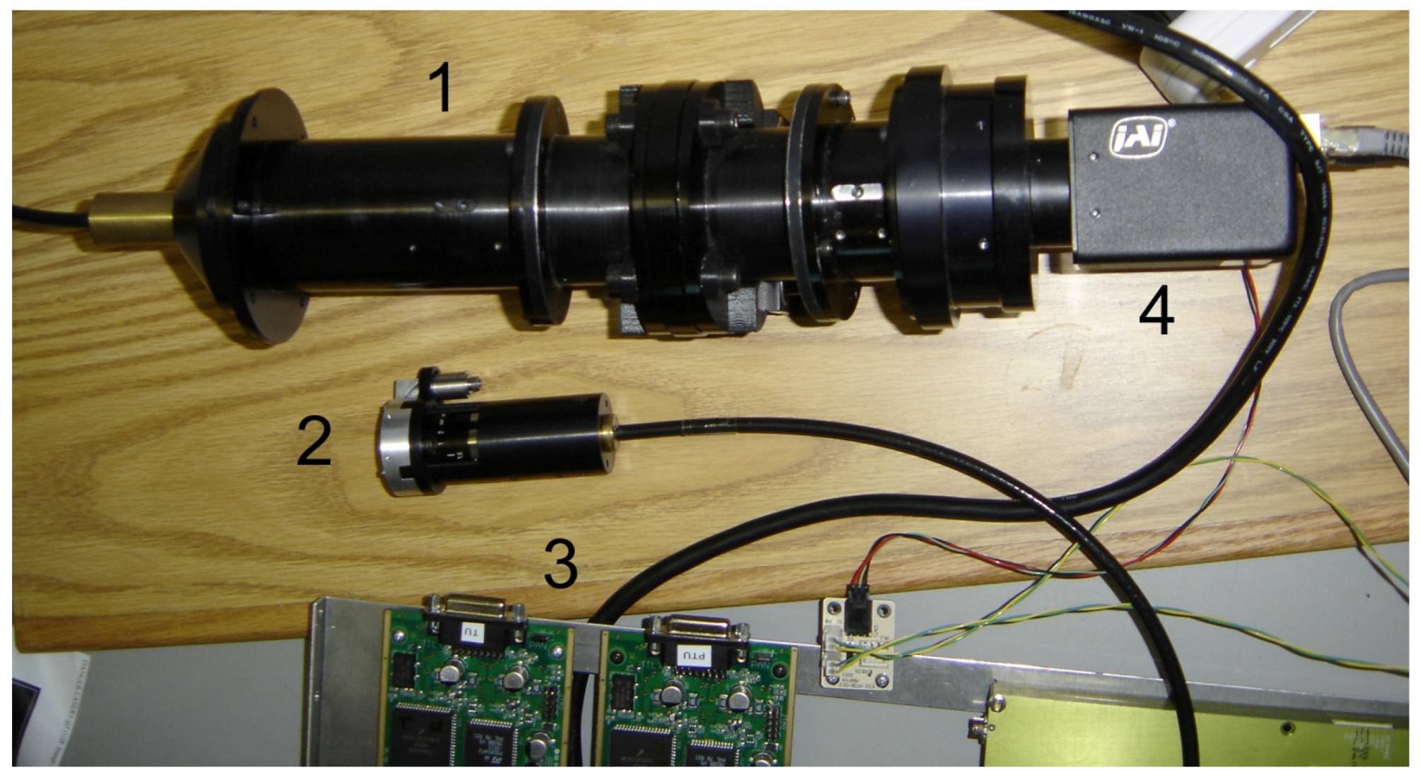
:
1. Introduction
1.1. Problems and Trends
1.2. Multifunctional Systems
1.3. Background and General Requirements
- (1)
- monitor general environmental conditions for security purposes;
- (2)
- remotely monitor patient temperature, pulse and breath intensity and content;
- (3)
- deliver scheduled medication;
- (4)
- carry medical instrumentation, such as a vein visualizer, defibrillator, emergency medications in a pen syringe, etc.;
- (5)
- be capable of self-charging from any electrical outlet in the hospital building;
- (6)
- communicate with doctors, the nursing station, hospital administration, security guards, patient’s relatives, etc.;
- (7)
- could be easily integrated into the Robotic Nurse network;
- (8)
- must be easily upgradable;
- (9)
- supply environmental, medical and security data in formats compatible with current standards, already existing systems, networks or medical instruments;
- (10)
- must be fabricated with the materials and use techniques that are allowed in healthcare areas.
1.4. Robotic Nurse Network
1.5. Other Applications
2. From Human Being to Robot
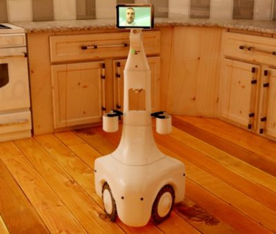
2.1. Moving Platform
2.1.1. Tracked and Wheeled
2.1.2. With Legs and Snake-Like
2.1.3. Specific Requirements
- (1)
- the robot “body” should be column-like: relatively smooth and with a narrow profile;
- (2)
- to move stably, it must have a low centre of gravity and a relatively large pedestal;
- (3)
- to see “over a crowd”, it must have a camera tower of changeable height and angle of viewing;
- (4)
- to estimate the scene adequately, the distance to obstacles and to find the optimal route, the robot should possess a stereo-camera and rangefinders;
- (5)
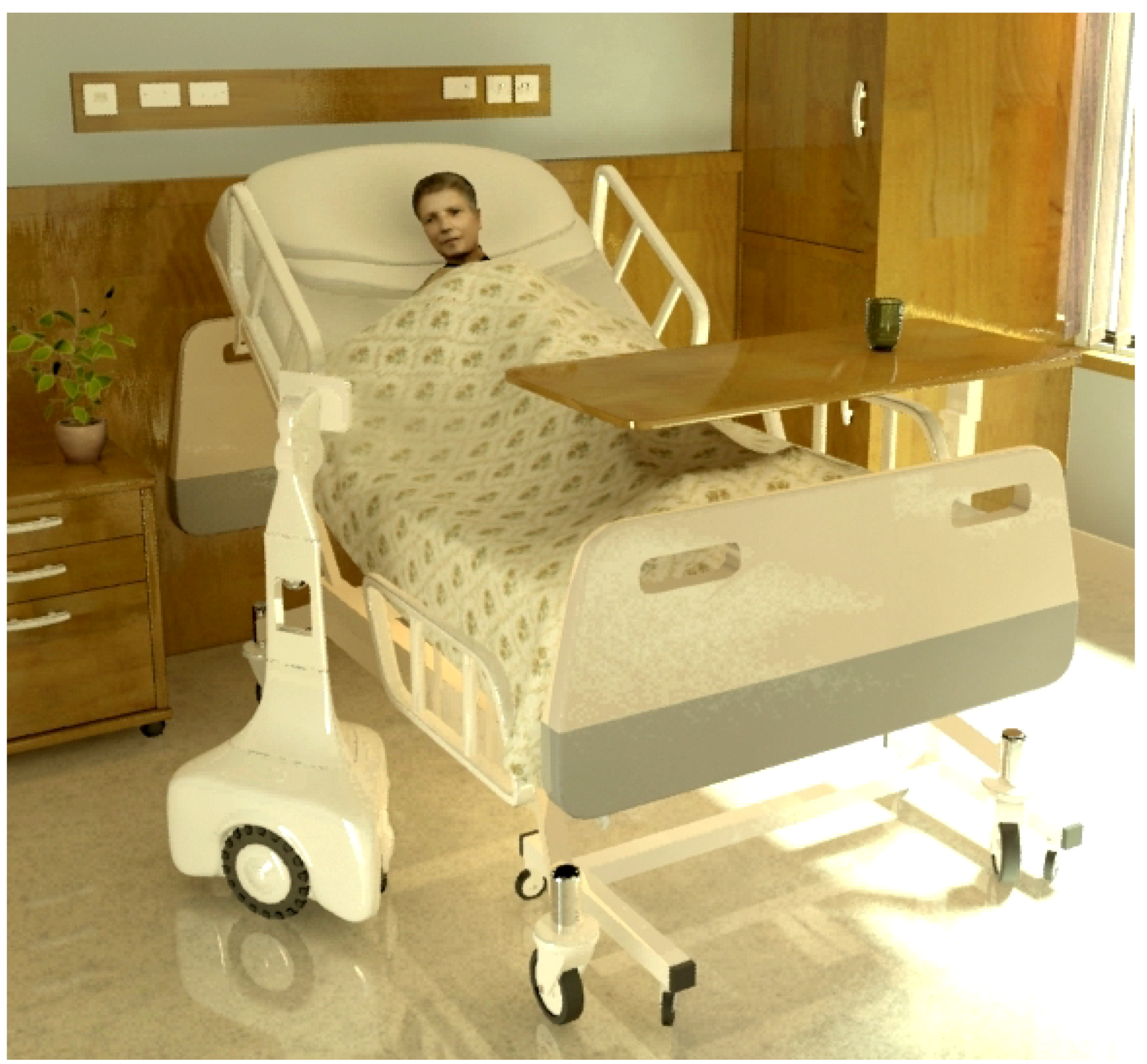
- the screen position should be slightly higher than the head of a patient in bed;
- (6)
- it is preferable that the cameras operate in different spectral ranges;
- (7)
- the robot must navigate and move autonomously without the close presence of hospital personnel.
2.1.4. RN Mechanics and Algorithms of Motion

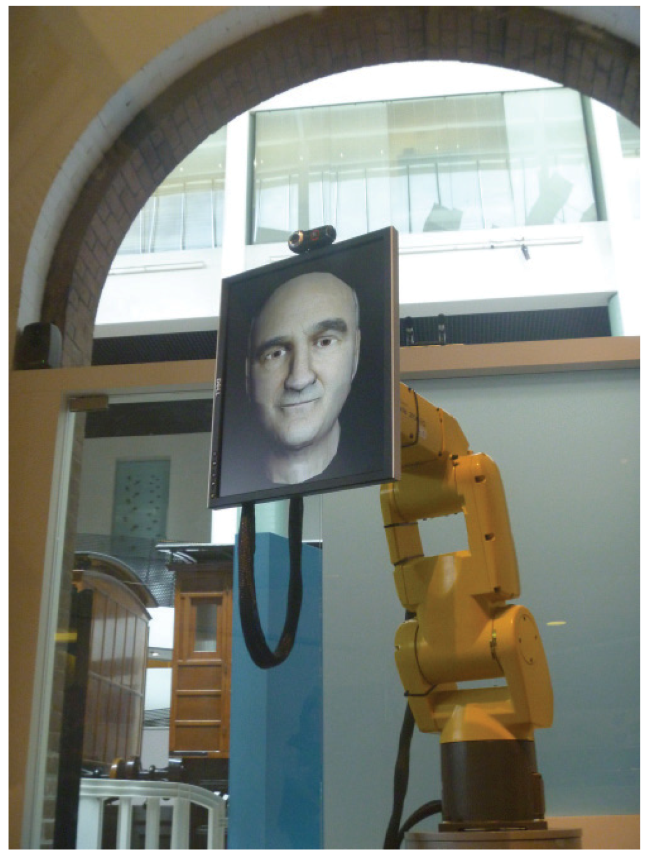
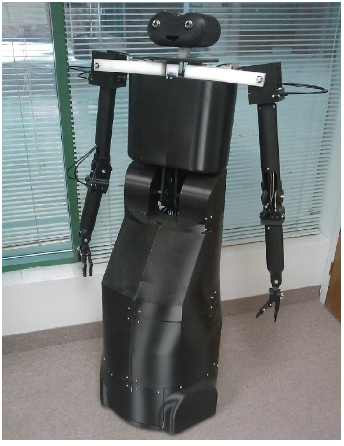
2.2. Arms/Hands (Manipulators)
2.3. Navigation and Safety Operation
2.3.1. Concepts and Solutions
2.3.2. Rangefinders
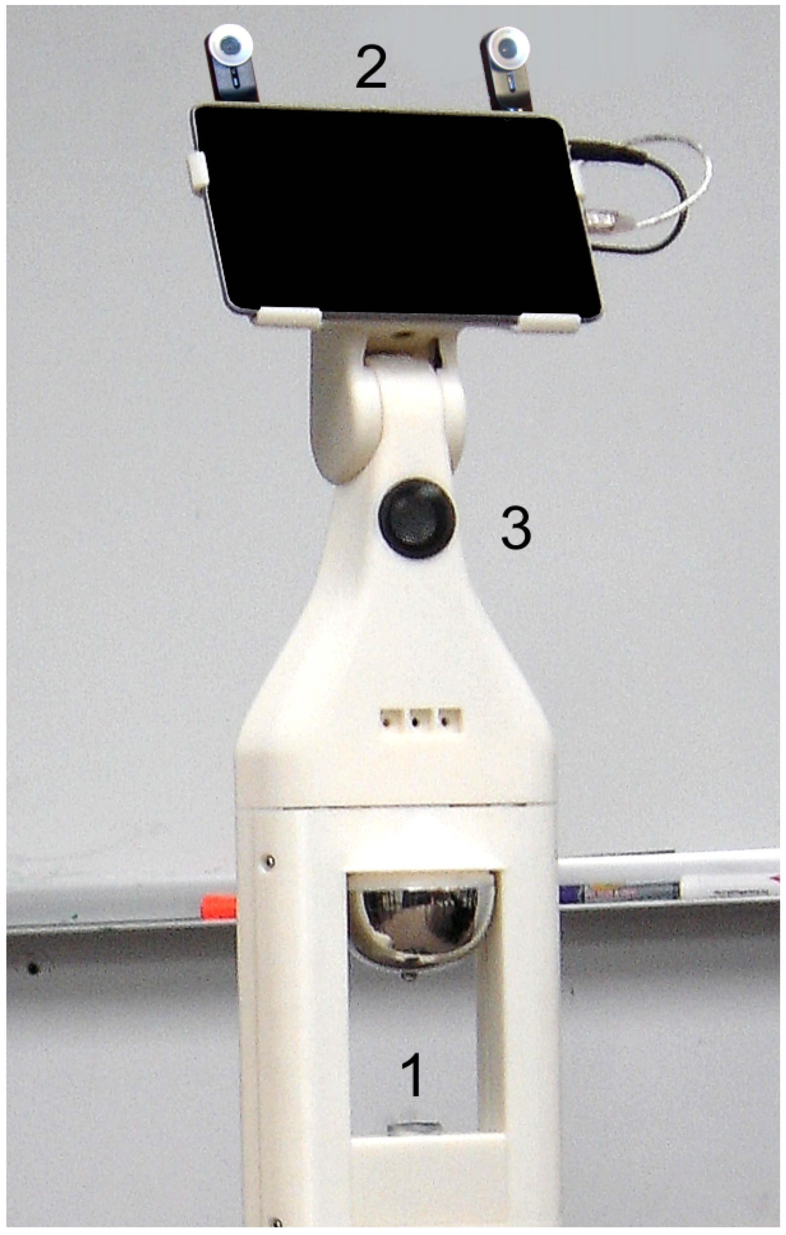
2.3.3.Cameras
2.4. Communication

2.5. Face Recognition
3. Next Step RN Evolution
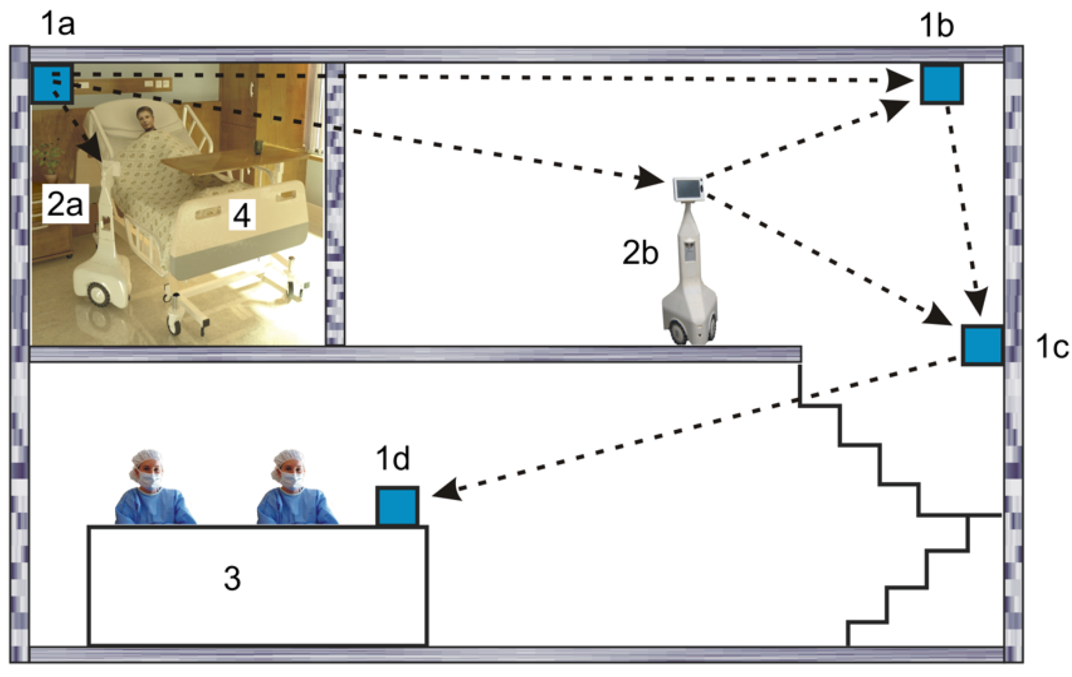
4. Distributed Robotic Nurse
4.1. General Structure of the Robotic Nurse Network
4.2. Homogeneous Sensory Network

4.3. Stationary Sensory Nodes
4.4. Inhomogeneous Network
5. Instruments and Technologies
5.1. General Principles
5.2. Innovations
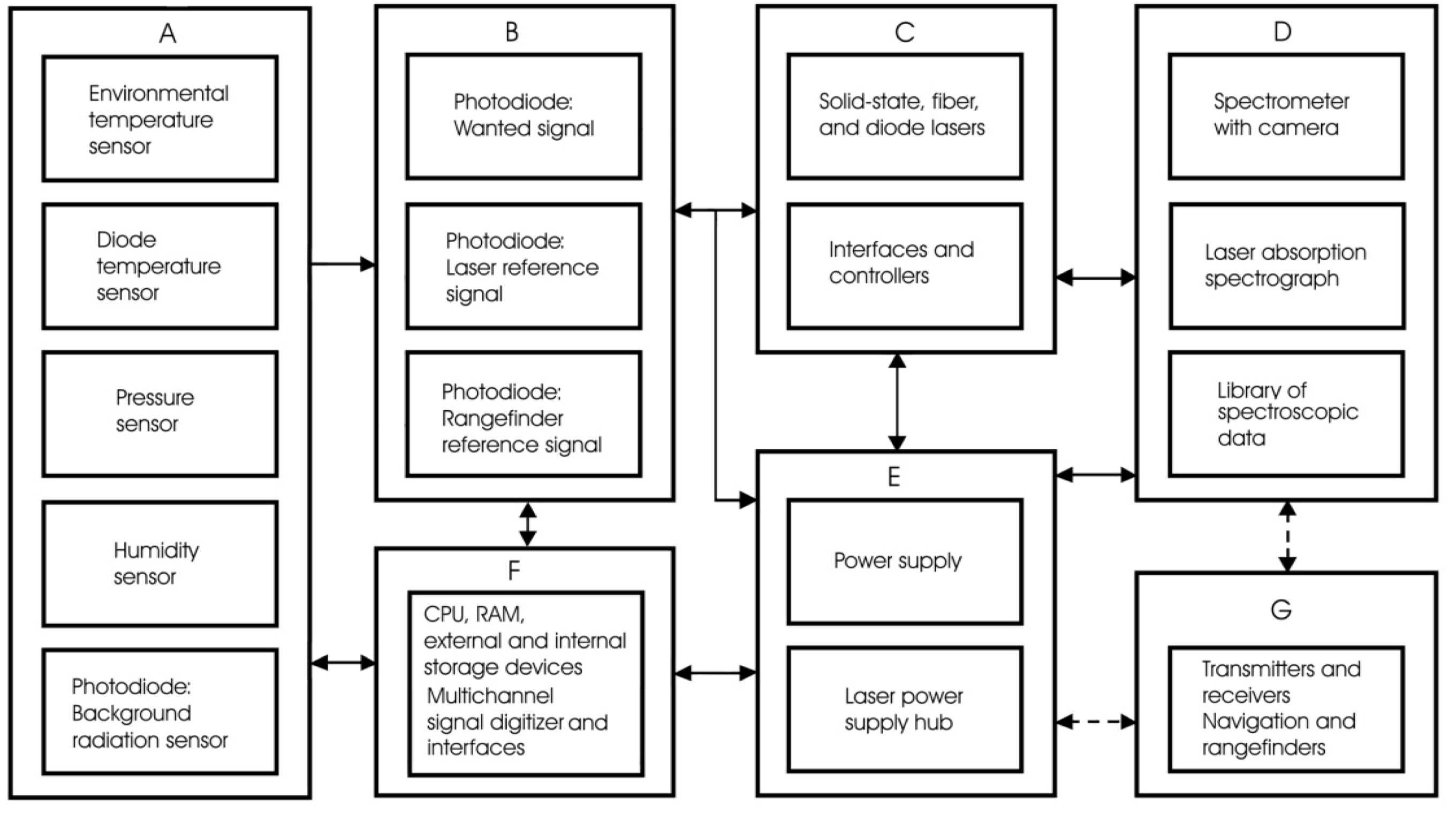
5.3. Sensor Block Diagram
5.4. Gas Sensor
5.4.1. What for?
- monitoring of the regular atmospheric gaseous conditions;
- alarming in case of emergency (fire, chemical agents, etc.);
- patient exhausting gases content monitoring for disease diagnostics purposes.
5.4.2. Ultrasound, Semiconductor, Electrochemical and Optical
5.4.3. Spectroscopic Sensors
5.5. Lasers for Remote Sensing
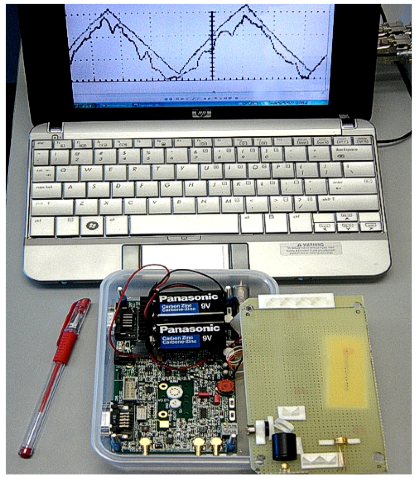
5.5.1. Single-Frequency Laser with Nano-Selector
5.5.2. Fiber Lasers
5.5.3. Diode Tunable Lasers
5.6. Multi-Gas Spectroscopic Sensor
5.6.1. Spectroscopic Sensor on the Robot
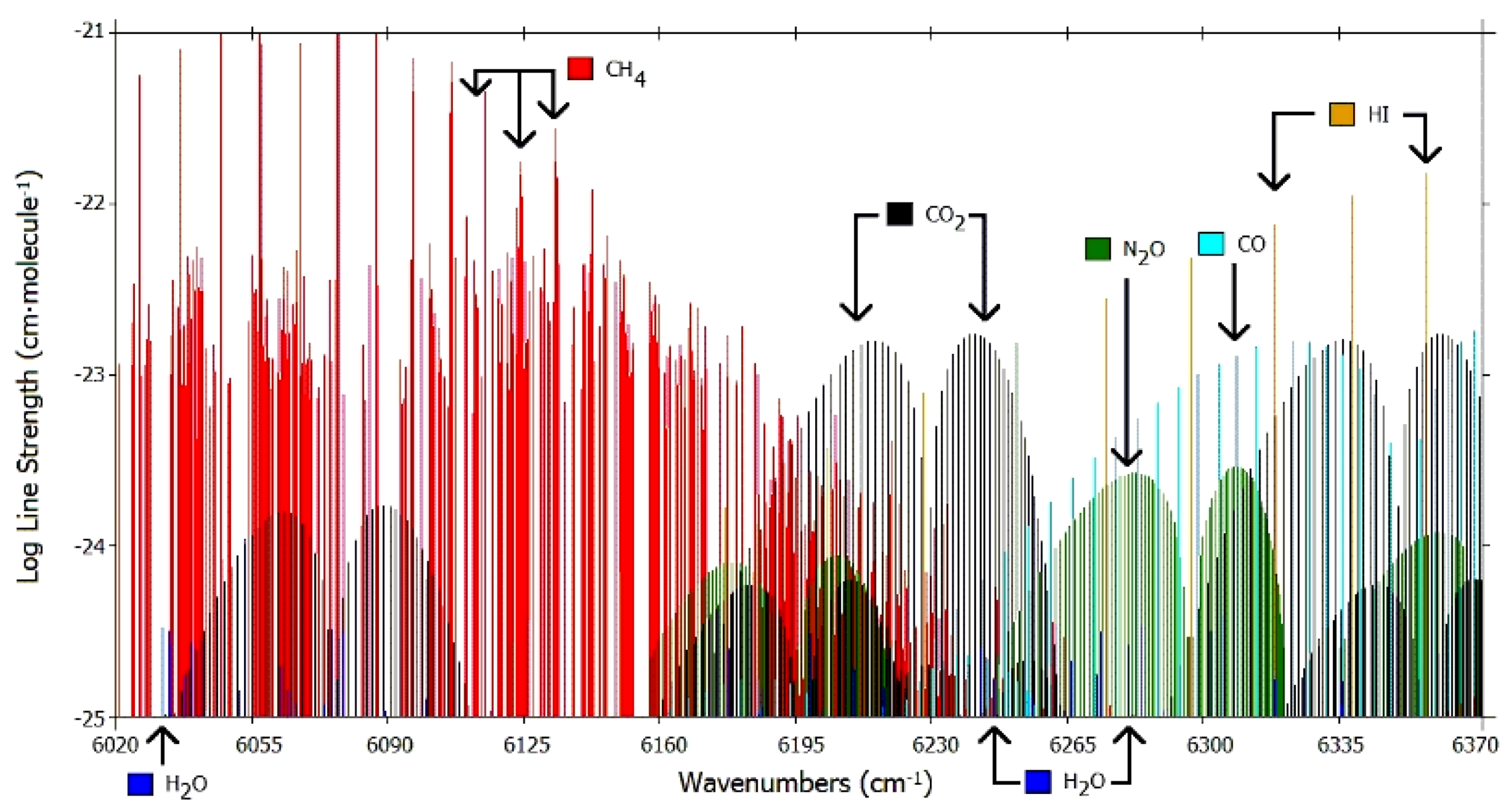
5.6.2. Appropriate Spectral Range

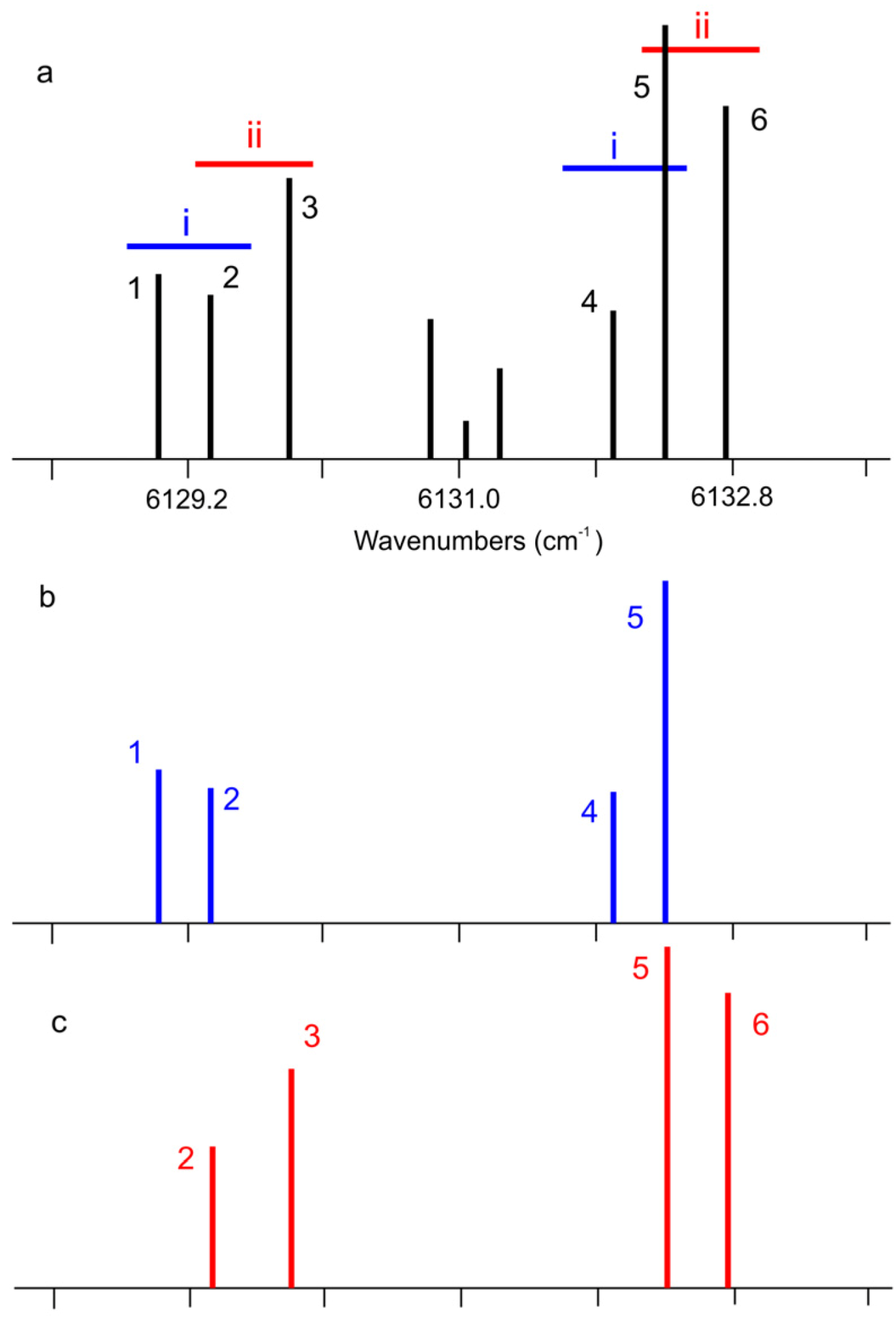
5.6.3. Identification of Operational Spectral Range

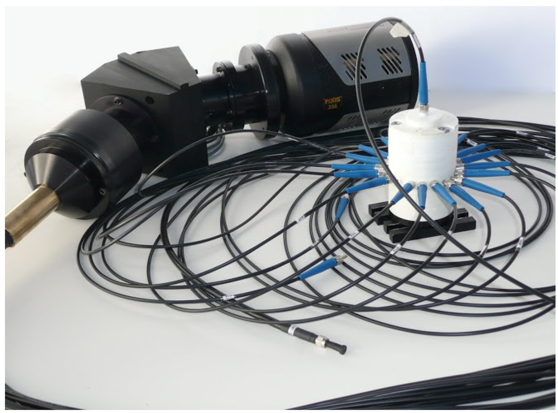
5.7. Spectrometer—The Key Element

5.8. Applications
5.8.1. Spectroscopy Biomedical Applications
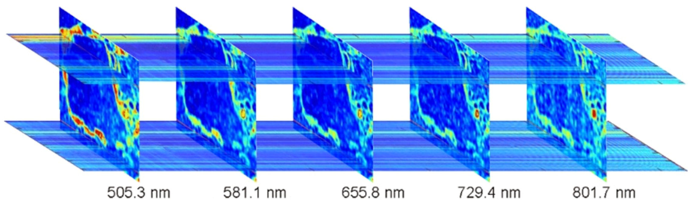
5.8.2. Raman Spectroscopy Medical Applications
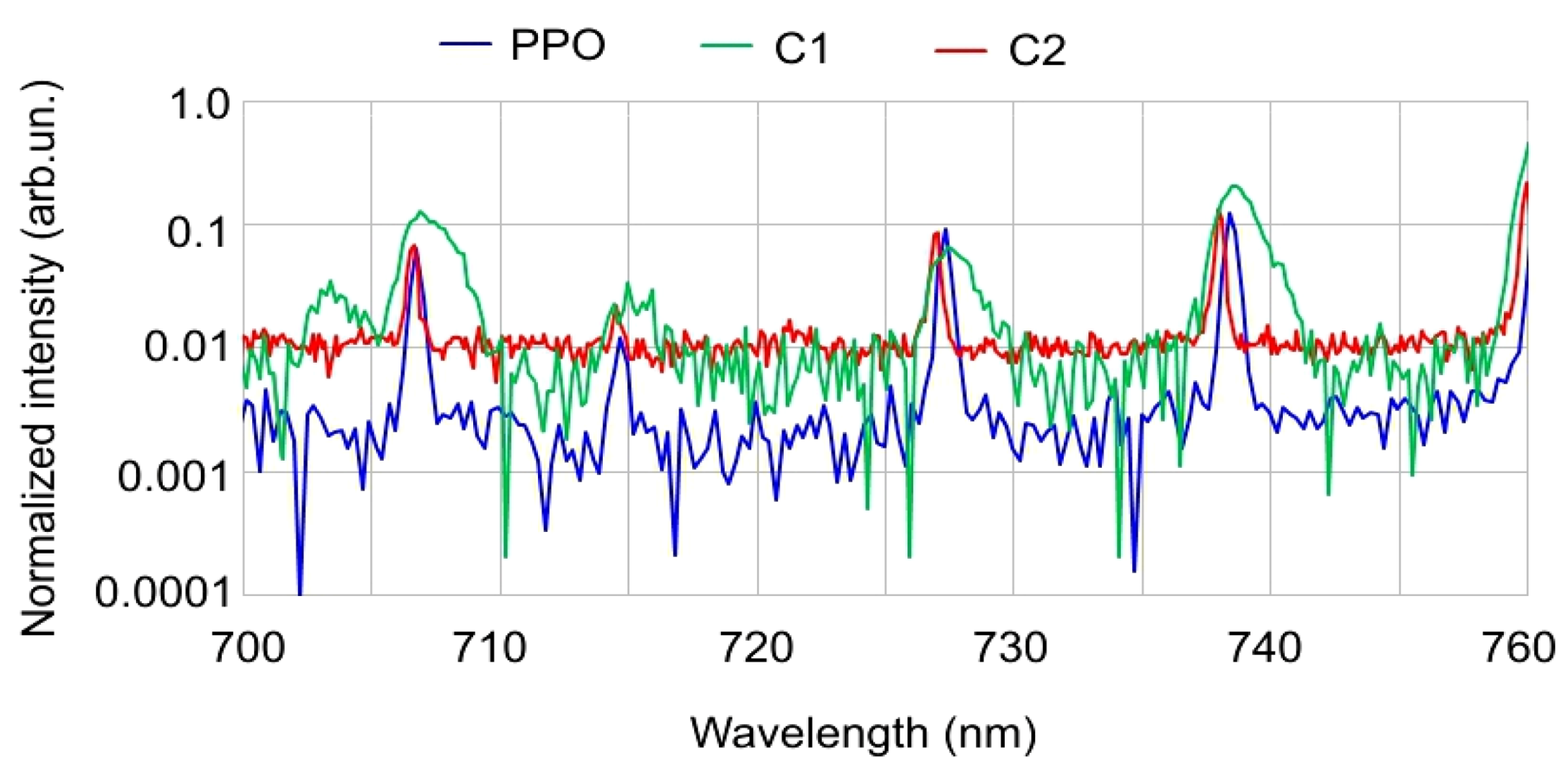
5.8.3. Universal Spectrometer

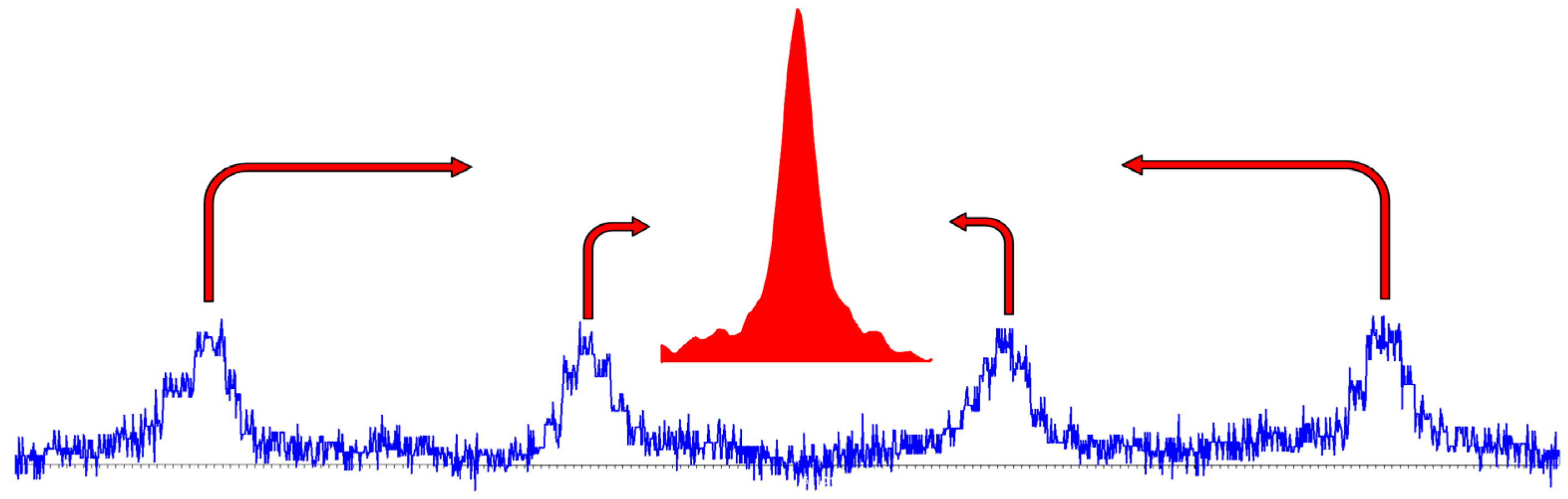
5.8.4. Raman Spectroscopy Applications
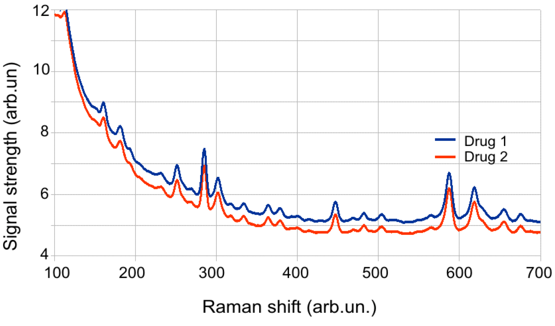
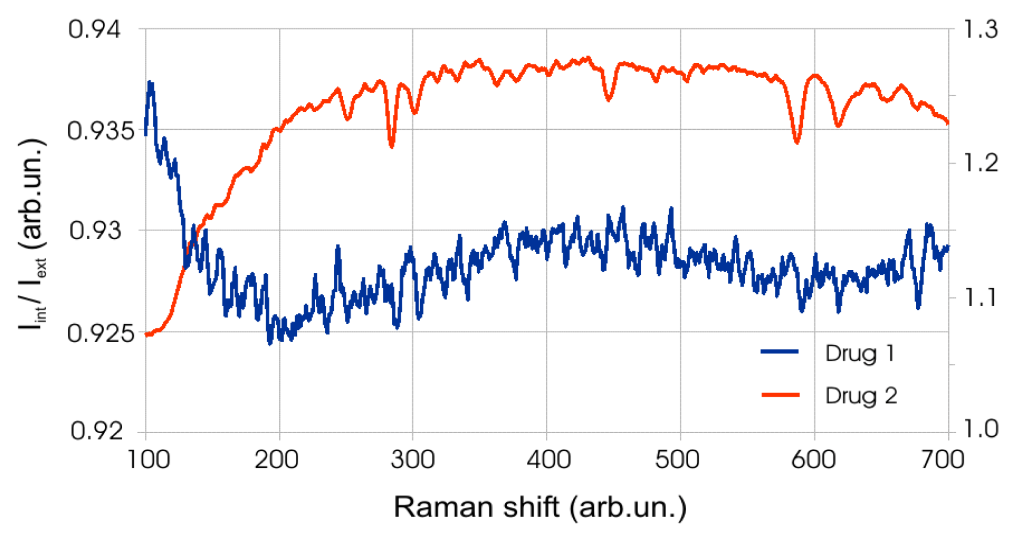
5.8.5. Medications Control
6. Electronics
7. Conclusions.
- (1)
- hospitals;
- (2)
- kindergartens, schools, colleges and universities;
- (3)
- private homes and public places;
- (4)
- banks, government buildings; railway stations, bus terminals and other populated areas.
Acknowledgments
Conflict of Interest
Reference and Notes
- Frankenstein. Available online: http://en.wikipedia.org/wiki/Frankenstein (accessed on 2 January 2013).
- Japanese Nurse Robot (Actroid-F) 2010. Available online: http://www.youtube.com/watch?v=I7tYwnqot6M (accessed on 28 November 2012).
- Matharoo, I.; Peshko, I.; Goldenberg, A. Robotic reconnaissance platform. I. Spectroscopic instruments with rangefinders. Rev. Sci. Instrum. 2011, 82, 113107:1–113107:15. [Google Scholar]
- Engineering Services, Inc. Homepage. Available online: http://www.esit.com (accessed on 2 January 2013).
- Peshko, I. Smart Synergistic Security Sensory Network for Harsh Environment: Net4S. In Nuclear Power: Control, Reliability and Human Factors; Tsvetkov, P., Ed.; InTech: Rijeka, Croatia, 2011; pp. 85–100. [Google Scholar]
- Peshko, I. New-Generation Security Network with Synergistic IP-Sensors. In Proceedings of Optics East Advanced EnvironmentalChemicaland Biological Sensing Technologies V, Boston, MA, USA, 9–12 September 2007; pp. 34–46.
- RP–7i ROBOT. Available online: http://www.intouchhealth.com/products-and-services/products/rp-7i-robot/ (accessed on 2 January 2013).
- Robotics/Types of Robots/Wheeled. Available online: http://en.wikibooks.org/wiki/Robotics/Types_of_Robots/Wheeled_ (accessed on 2 January 2013).
- Foster-Miller TALON. Available online: http://en.wikipedia.org/wiki/Foster-Miller_TALON (accessed on 2 January 2013).
- Hexapod (robotics). Available online: http://en.wikipedia.org/wiki/Hexapod_(robotics) (accessed on 2 January 2013).
- Snakebot. Available online: http://en.wikipedia.org/wiki/Snakebot (accessed on 2 January 2013).
- CrossWing Homepage. Available online: http://www.crosswing.com (accessed on 2 January 2013).
- The Future of Humanoid Robots—Research and Applications; Zaier, R. (Ed.) InTech: Rijeka, Croatia, 2012.
- Robot. Manipulators, New Achievements; Lazinica, A.; Kawai, H. (Eds.) InTech: Rijeka, Croatia, 2010.
- Robot. Arms; Goto, S. (Ed.) InTech: Rijeka, Croatia, 2011.
- Tsuji, T.; Harada, K.; Kaneko, K.; Kanehiro, F.; Maruyama, K. Grasp Planning for a Humanoid Hand. In The Future of Humanoid Robots—Research and Applications; Zaier, R., Ed.; InTech: Rijeka, Croatia, 2012; pp. 63–80. [Google Scholar]
- Choi, D.; Lee, D.-W.; Shon, W.; Lee, H.-G. Design of 5 D.O.F Robot Hand with an Artificial Skin for an Android Robot. In The Future of Humanoid Robots—Research and Applications; Zaier, R., Ed.; InTech: Rijeka, Croatia, 2012; pp. 81–96. [Google Scholar]
- Fukui, W.; Kobayashi, F.; Kojima, F. Development of Multi-Fingered Universal Robot Hand with Torque Limiter Mechanism. In The Future of Humanoid Robots—Research and Applications; Zaier, R., Ed.; InTech: Rijeka, Croatia, 2012; pp. 97–108. [Google Scholar]
- Lee, S. MFR (Multi-purpose Field Robot) based on Human-Robot Cooperative Manipulation for Handling Building Materials. In Robot Manipulators, New Achievements; Lazinica, A., Kawai, H., Eds.; InTech: Rijeka, Croatia, 2010; pp. 289–313. [Google Scholar]
- Lima, M.F.M.; Machado, J.A.T.; Ferrolho, A. A Sensor Classification Strategy for Robotic Manipulators. In Robot Manipulators, New Achievements; Lazinica, A., Kawai, H., Eds.; InTech: Rijeka, Croatia, 2010; pp. 315–328. [Google Scholar]
- Beran, T.N.; Ramirez-Serrano, A. Robot Arm-Child Interactions: A Novel Application Using Bio-Inspired Motion Control. In Robot Arms; Goto, S., Ed.; InTech: Rijeka, Croatia, 2011; pp. 241–262. [Google Scholar]
- Advances in Robot Navigation; Barrera, A. (Ed.) InTech: Rijeka, Croatia, 2011.
- Fujita, T.; Kondo, Y. 3D Terrain Sensing System using Laser Range Finder with Arm-Type Movable Unit. In Robot Arms; Goto, S., Ed.; InTech: Rijeka, Croatia, 2011; pp. 159–174. [Google Scholar]
- Kawai, H.; Murao, T.; Fujita, M. Passivity-Based Visual Force Feedback Control for Eye-to-Hand Systems. In Robot Manipulators, New Achievements; Lazinica, A., Kawai, H., Eds.; InTech: Rijeka, Croatia, 2010; pp. 329–342. [Google Scholar]
- Funabora, Y.; Yano, Y.; Doki, S.; Okuma, S. Autonomous Motion Adaptation Against Structure Changes Without Model Identification. In The Future of Humanoid Robots—Research and Applications; Zaier, R., Ed.; InTech: Rijeka, Croatia, 2012; pp. 29–40. [Google Scholar]
- Gams, A.; Petric, T.; Ude, A.; Žlajpah, L. Performing Periodic Tasks: On-Line Learning, Adaptation and Synchronization with External Signals. In The Future of Humanoid Robots—Research and Applications; Zaier, R., Ed.; InTech: Rijeka, Croatia, 2012; pp. 3–28. [Google Scholar]
- Design of Oscillatory Neural Network for Locomotion Control of Humanoid Robots. In The Future of Humanoid Robots—Research and Applications; Zaier, R. (Ed.) InTech: Rijeka, Croatia, 2012; pp. 41–60.
- R2D2, MD—Will Your Next Doctor Be a Robot? Available online: http://wraltechwire.com/business/tech_wire/news/blogpost/7301564/ (accessed on 02 January 2013).
- Kroos, C.; Herath, D.C.; Stelarc. From Robot Arm to Intentional Agent: The Articulated Head. In Robot Arms; Goto, S., Ed.; InTech: Rijeka, Croatia, 2011; pp. 215–240. [Google Scholar]
- Matsusaka, Y. Speech Communication with Humanoids: How People React and How We Can Build the System. In The Future of Humanoid Robots—Research and Applications; Zaier, R., Ed.; InTech: Rijeka, Croatia, 2012; pp. 165–188. [Google Scholar]
- Hasanuzzaman, M.; Ueno, H. User, Gesture and Robot Behaviour Adaptation for Human-Robot Interaction. In The Future of Humanoid Robots—Research and Applications; Zaier, R., Ed.; InTech: Rijeka, Croatia, 2012; pp. 229–256. [Google Scholar]
- Infantino, I. Affective Human-Humanoid Interaction Through Cognitive Architecture. In The Future of Humanoid Robots—Research and Applications; Zaier, R., Ed.; InTech: Rijeka, Croatia, 2012; pp. 147–164. [Google Scholar]
- Facial Recognition System. Available online: http://en.wikipedia.org/wiki/Facial_recognition_system (accessed on 2 January 2013).
- TOSHIBA Face Recognition. Available online: http://toshiba-face-recognition.software.informer.com/ (accessed on 2 January 2013).
- FUJIFILM Canada. Available online: http://www.fujifilm.ca/products/digital_cameras/index.html (accessed on 2 January 2013).
- Nanomedicine. Available online: http://en.wikipedia.org/wiki/Nanomedicine (accessed on 02 January 2013).
- Matharoo, I.; Peshko, I. Smart spectroscopy sensors: II. Narrow-band laser systems. Opt. Laser Eng. 2013, 51, 270–277. [Google Scholar] [CrossRef]
- New Mountain NM150WX. Available online: http://www.weathershack.com/product/new-mountain-nm150wx.html (accessed on 02 January 2013).
- La Crosse Technology. Available online: http://www.lacrossetechnology.com/ws.php (accessed on 2 January 2013).
- Wojtas, J.; Bielecki, Z.; Stacewicz, T.; Mikolajczyk, J.; Nowakowski, M. Ultrasensitive laser spectroscopy for breath analysis. Opto. Electron. Rev. 2012, 20, 26–39. [Google Scholar] [CrossRef]
- Wang, C.; Mandelis, A.; Garcia, J.A. Detectivity comparison between thin-film Pd/PVDF photopyroelectric interferometric and optical reflectance hydrogen sensors. Rev. Sci. Instrum. 1999, 70, 4370–4376. [Google Scholar] [CrossRef]
- RKI Instruments. Gas Detection for Life. Available online: http://www.rkiinstruments.com (accessed on 2 January 2013).
- MultiRAE Pro Wireless Portable Multi-Threat Monitor for Radiation and Chemical Detection. Available online: http://www.raesystems.com/products/multirae-pro (accessed on 8 May 2013).
- Moseley, P.T. Solid state gas sensors. Meas. Sci. Technol. 1997, 8, 223–237. [Google Scholar] [CrossRef]
- Model IQ-1000: 100+ Gas Portable. Available online: http://www.intlsensor.com/pdf/IQ1000.pdf (accessed on 2 January 2013).
- Wang, C.; Mandelis, A. Instrumental noise and detectivity analysis of photopyroelectric destructive thermal-wave interferometry. Rev. Sci. Instrum. 2000, 71, 1961–1970. [Google Scholar] [CrossRef]
- Cubillas, A.M.; Lazaro, J.M.; Conde, O.M.; Petrovich, M.N.; Lopez-Higuera, J.M. Multi-line fit model for the detection of methane at ν2 + 2ν3 band using hollow-core photonic bandgap Fibres. Sensors 2009, 9, 490–502. [Google Scholar]
- Toda, H. The precise mechanisms of a high-speed ultrasound gas sensor and detecting human-specific lung gas exchange. Int. J. Adv. Robotic Syst. 2012, 9, 249:1–249:9. [Google Scholar]
- Capnography. Available online: http://en.wikipedia.org/wiki/Capnography (accessed on 2 January 2013).
- RAID M100: Extensive Portable Capability. Available online: http://www.bruker.com/en/products/mobile-detection/ims/raid-m100/overview.html (accessed on 8 May 2013).
- SABRE 5000. Available online: http://www.smithsdetection.com/sabre5000explosives.php (accessed on 2 January 2013).
- Rothman, L.S.; Gordon, I.E.; Barbe, A.; ChrisBenner, D.; Bernath, P.F.; Birk, M.; Boudon, V.; Brown, L.R.; Campargue, A.; Champion, J.-P.; et al. The HITRAN 2008 molecular spectroscopic database. J. Quat. Spectrosc. Radiat. Transf. 2009, 110, 533–572. [Google Scholar] [CrossRef]
- NIST Atomic Spectra Database Lines Form. Available online: http://physics.nist.gov/PhysRefData/ASD/lines_form.html (accessed on 2 January 2013).
- Platt, U.; Stutz, J. Differential Optical Absorption Spectroscopy: Principles and Applications; Springer-Verlag: Berlin, Germany, 2008. [Google Scholar]
- Heard, D.E. Analytical Techniques for Atmospheric Measurement; Blackwell Publishing: Oxford, UK, 2006. [Google Scholar]
- Werle, P.; Slemr, F.; Maurer, K.; Kormann, R.; Mücke, R.; Jänker, B. Near- and mid-infrared laser-optical sensors for gas analysis. Opt. Lasers Eng. 2002, 37, 101–114. [Google Scholar] [CrossRef]
- Totschnig, G.; Lackner, M.; Shau, R.; Ortsiefer, M.; Rosskopf, J.; Amann, M.-C.; Winter, F. 1.8 μm vertical-cavity surface-emitting laser absorption measurements of HCl, H2O and CH4. Meas. Sci. Technol. 2003, 14, 472–478. [Google Scholar] [CrossRef]
- Lackner, M.; Totschnig, G.; Winter, F.; Ortsiefer, M.; Amann, M.-C.; Shau, R.; Rosskopf, J. Demonstration of methane spectroscopy using a vertical-cavity surface-emitting laser at 1.68 μm with up to 5 MHz repetition rate. Meas. Sci. Technol. 2003, 14, 101–106. [Google Scholar] [CrossRef]
- Hofmann, W.; Amann, M.-C. Long-wavelength vertical-cavity surface-emitting lasers for high-speed applications and gas sensing. IET Optoelectron. 2008, 2, 134–142. [Google Scholar] [CrossRef]
- LaserTechnik Berlin. Available online: http://www.ltb-berlin.de/Spectrometers.93.0.html?&L=1&gclid=COfhxa-UmKoCFchM4AodjWNWxA (accessed on 02 January 2013).
- HORIBA Scientific. Available online: http://www.horiba.com/us/en/scientific/products/spectrometers (accessed on 02 January 2013).
- HR4000 High-Resolution Spectrometer. Available online: http://www.oceanoptics.com/products/hr4000.asp (accessed on 2 January 2013).
- P&P Optica. Available online: http://www.ppo.ca (accessed on 2 January 2013).
- Zahniser, M.; Nelson, D.; McManus, J.; Kebabian, P.; Lloyd, D. Measurement of trace gas flexes using tunable diode laser spectroscopy. Philos. Trans. R. Soc. London Phys. Sci. Eng. 1995, 351, 371–382. [Google Scholar] [CrossRef]
- Arroyo, M.P.; Hanson, R.K. Absorption measurements of water-vapor concentration, temperature, and line-shape parameters using a tunable InGaAsP diode laser. Appl. Opt. 1993, 32, 6104–6116. [Google Scholar] [CrossRef]
- Jabczyński, J.; Firak, J.; Peshko, I. Single-frequency, thin-film tuned, 0.6 W diode-pumped Nd:YVO4 laser. Appl. Opt. 1997, 36, 2484–2490. [Google Scholar] [CrossRef]
- Peshko, I.; Jabczyński, J.; Firak, J. Tunable single- and double-frequency diode-pumped Nd:YAG laser. IEEE J. Quant. Electron. 1997, 33, 1417–1423. [Google Scholar] [CrossRef]
- Digonnet, M.J.F. Rare-Earth-Doped Fiber. Lasers and Amplifiers; Marcel Dekker, Inc.: New York, NY, USA, 2001. [Google Scholar]
- Sacher Lasertechnik Group. Available online: http://www.sacher-laser.com (accessed on 28 November 2012).
- DFB—Distributed Feedback Diodes. Available online: http://www.toptica.com/?id=127 (accessed on 8 May 2013).
- Maclean, A.J.; Kemp, A.J.; Calves, S.; Kim, J.-Y.; Kim, T.; Dawson, M.D.; Burns, D. Continuous tuning and efficient intracavity second-harmonic generation in a semiconductor disk laser with an intracavity diamond heatspreader. IEEE J. Quantum. Electron. 2008, 41, 216–225. [Google Scholar]
- Absorption Spectroscopy. Available online: http://en.wikipedia.org/wiki/Absorption_spectroscopy (accessed on 2 January 2013).
- Laser-induces Fluorescence. Available online: http://en.wikipedia.org/wiki/Laserinduced_fluorescence (accessed on 2 January 2013).
- Raman Spectroscopy. Available online: http://en.wikipedia.org/wiki/Raman_spectroscopy (accessed on 2 January 2013). [Green Version]
- Imaging Spectroscopy. Available online: http://en.wikipedia.org/wiki/Imaging_spectroscopy (accessed on 2 January 2013). [Green Version]
- Barzda, V. Non-Linear Contrast Mechanisms for Optical Microscopy. In Biophysical Techniques in Photosynthesis II; Aartsma, T., Matysik, J., Eds.; Springer: Dordrecht, Netherland, 2008; Volume 2, pp. 35–54. [Google Scholar]
- Weisberg, A.; Craparo, J.; de Saro, R.; Pawluczyk, R. Comparison of transmission grating spectrometer to a reflective grating spectrometer for standoff laser-induced breakdown spectroscopy measurements. Appl. Opt. 2010, 49, C200–C210. [Google Scholar] [CrossRef]
- Mars Science Laboratory. Available online: http://www.nasa.gov/mission_pages/msl/index.html (accessed on 2 January 2013). [Green Version]
- Das, R.S.; Agrawal, Y.K. Raman spectroscopy: Recent advancements, techniques and applications. Vibrational. Spectrosc. 2011, 57, 163–176. [Google Scholar] [CrossRef]
- Mogilevsky, G.; Borland, L.; Brickhouse, M.; Fountain, A.W., III. Raman spectroscopy for homeland security applications. Int. J. Spectrosc. 2012, 2012. [Google Scholar] [CrossRef]
- Matousek, P. Deep non-invasive Raman spectroscopy of living tissue and powders. Chem. Soc. Rev. 2007, 36, 1292–1304. [Google Scholar] [CrossRef]
- Hargreaves, M.D.; Macleod, N.A.; Brewster, V.L.; Munshi, T.; Edwards, H.G.M.; Matousek, P. Application of portable Raman spectroscopy and bench-top spatially offset Raman spectroscopy to interrogate concealed biomaterials. J. Raman Spectrosc. 2009, 40, 1875–1880. [Google Scholar] [CrossRef]
- Dieringer, J.A.; McFarland, A.D.; Shah, N.C.; Stuart, D.A.; Whitney, A.V.; Yonzon, C.R.; Young, M.A.; Zhang, X.; van Duyne, R.P. Surface enhanced Raman spectroscopy: New materials, concepts, characterization tools, and applications. Faraday Discuss. 2006, 132, 9–26. [Google Scholar] [CrossRef]
- Zhang, X.; Young, M.A.; Lyandres, O.; van Duyne, R.P. Rapid detection of an anthrax biomarker by surface-enhanced raman spectroscopy. J. Am. Chem. Soc. 2005, 127, 4484–4489. [Google Scholar]
- Östmark, H.; Nordberg, M.; Carlsson, T.E. Stand-off detection of explosives particles by multispectral imaging Raman spectroscopy. Appl. Opt. 2011, 50, 5592–5599. [Google Scholar] [CrossRef]
- Kraft, C.; Knetschke, Siegner, T.A.; Funk, R.H.W.; Salzer, R. Mapping of single cells by near infrared Raman microspectroscopy. Vib. Spectrosc. 2003, 32, 75–83. [Google Scholar] [CrossRef]
- Notingher, I. Raman spectroscopy cell-based biosensors. Sensors 2007, 7, 1343–1358. [Google Scholar] [CrossRef]
- Pawluczyk, O.; Blackmore, K.; Dick, S.; Lilge, L. High-Performance Broad-Band Spectroscopy for Breast Cancer Risk Assessment. In Proceedings of the SPIE: Photonic Applications in Biosensing and Imaging, Toronto, Canada, 30 September 2005; Wilson, B.C., Hornsey, R.I., Krull, U.J., Chan, W., Yu, K., Weersink, R.A., Eds.; Volume 5969, pp. 369–378.
- 2012 R & D 100 Award Winners. Available online: http://www.rdmag.com/Awards/RD-100-Awards/2012/06/R-D-100-2012-Winners-Overview/ (accessed on 28 November 2012).
- FiberTech Optica. Available online: http://www.fibertech-optica.com/ (accessed on 28 November 2012).
- Harvey, S.D.; Vucelick, M.E.; Lee, R.N.; Wright, B.W. Blind field test evaluation of Raman spectroscopy as a forensic tool. Forensic Sci. Int. 2002, 125, 12–21. [Google Scholar] [CrossRef]
- Hodges, C.M.; Akhavan, J. The use of Fourier Transform Raman spectroscopy in the forensic identification of illicit drugs and explosives. Spectrochim. Acta A Mol. Biomol. Spectrosc. 1990, 46, 303–307. [Google Scholar] [CrossRef]
- Armenta, S.; Garrigues, S.; de la Guardia, M. Solid-phase FT-Raman determination of caffeine in energy drinks. Anal. Chim. Acta 2005, 547, 197–203. [Google Scholar] [CrossRef]
- Hatab, N.A.; Eres, G.; Hatzinger, P.B.; Baohua, G. Detection and analysis of cyclotrimethylenetrinitramine (RDX) in environmental samples by surface-enhanced Raman spectroscopy. J. Raman Spectrosc. 2010, 41, 1131–1136. [Google Scholar] [CrossRef]
- Docherty, F.T.; Monaghan, P.B.; McHugh, C.J.; Graham, D.; Smith, W.E.; Cooper, J.M. Simultaneous multianalyte identification of molecular species involved in terrorism using raman spectroscopy. IEEE Sens. J. 2005, 5, 632–638. [Google Scholar]
- About ENERGY STAR. Available online: http://www.energystar.gov/index.cfm?c=about.ab_index (accessed on 2 January 2013).
- Reverter, F. The art of directly interfacing sensors to microcontrollers. J. Low Power Electron. Appl. 2012, 2, 265–281. [Google Scholar] [CrossRef]
- Electro-Optic Modulator. Available online: http://en.wikipedia.org/wiki/Electro-optic_modulator (accessed on 2 January 2013).
© 2013 by the authors; licensee MDPI, Basel, Switzerland. This article is an open access article distributed under the terms and conditions of the Creative Commons Attribution license (http://creativecommons.org/licenses/by/3.0/).
Share and Cite
Peshko, I.; Pawluczyk, R.; Wick, D. Synergistic Sensory Platform: Robotic Nurse. J. Low Power Electron. Appl. 2013, 3, 114-158. https://doi.org/10.3390/jlpea3020114
Peshko I, Pawluczyk R, Wick D. Synergistic Sensory Platform: Robotic Nurse. Journal of Low Power Electronics and Applications. 2013; 3(2):114-158. https://doi.org/10.3390/jlpea3020114
Chicago/Turabian StylePeshko, Igor, Romuald Pawluczyk, and Dale Wick. 2013. "Synergistic Sensory Platform: Robotic Nurse" Journal of Low Power Electronics and Applications 3, no. 2: 114-158. https://doi.org/10.3390/jlpea3020114
APA StylePeshko, I., Pawluczyk, R., & Wick, D. (2013). Synergistic Sensory Platform: Robotic Nurse. Journal of Low Power Electronics and Applications, 3(2), 114-158. https://doi.org/10.3390/jlpea3020114