
Synergistic Effect of Functionalized Nanokaolin Decorated MWCNTs on the Performance of Cellulose Acetate (CA) Membranes Spectacular

Abstract
:
1. Introduction
2. Results and Discussion
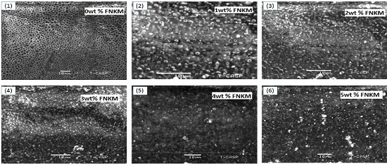
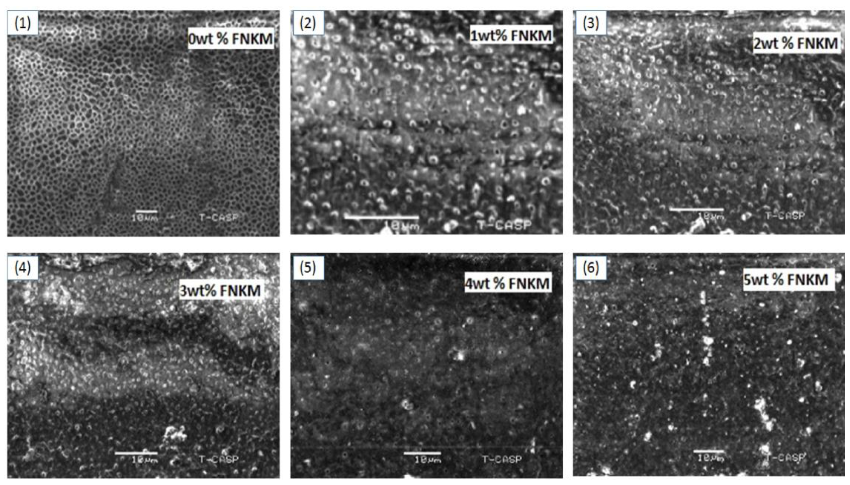
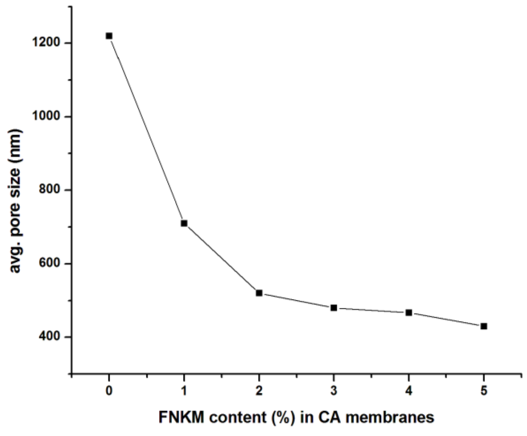
2.1. SEM Analysis
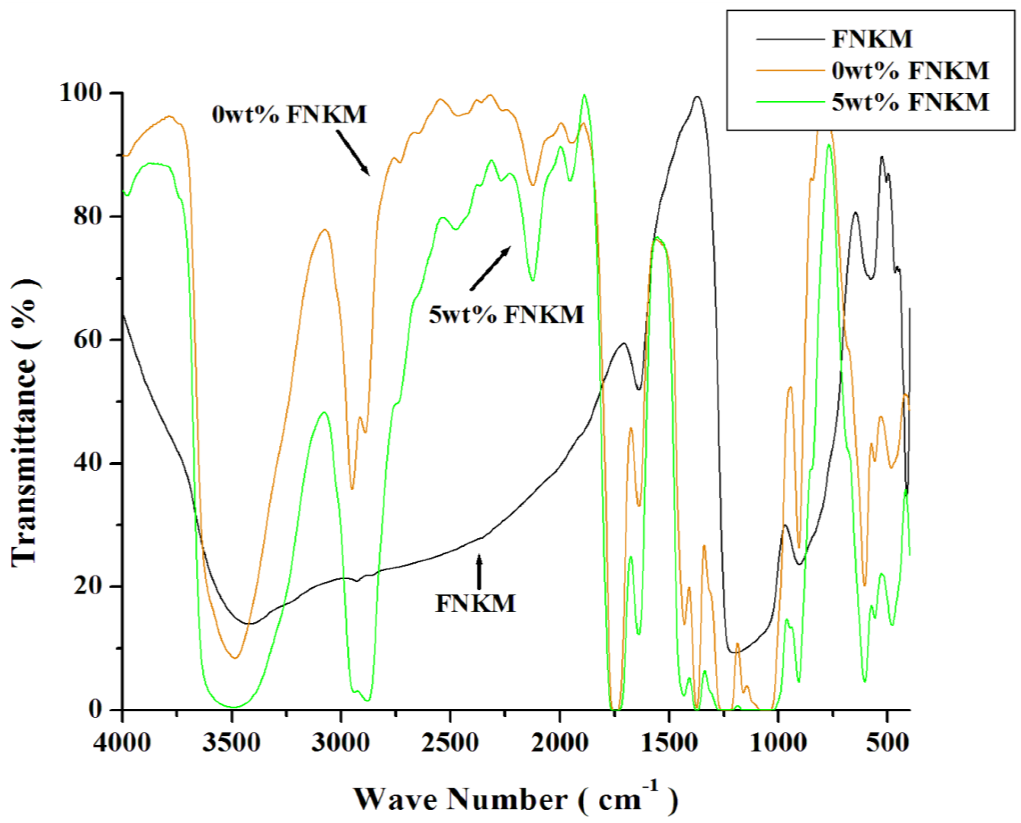
2.2. FTIR Analysis
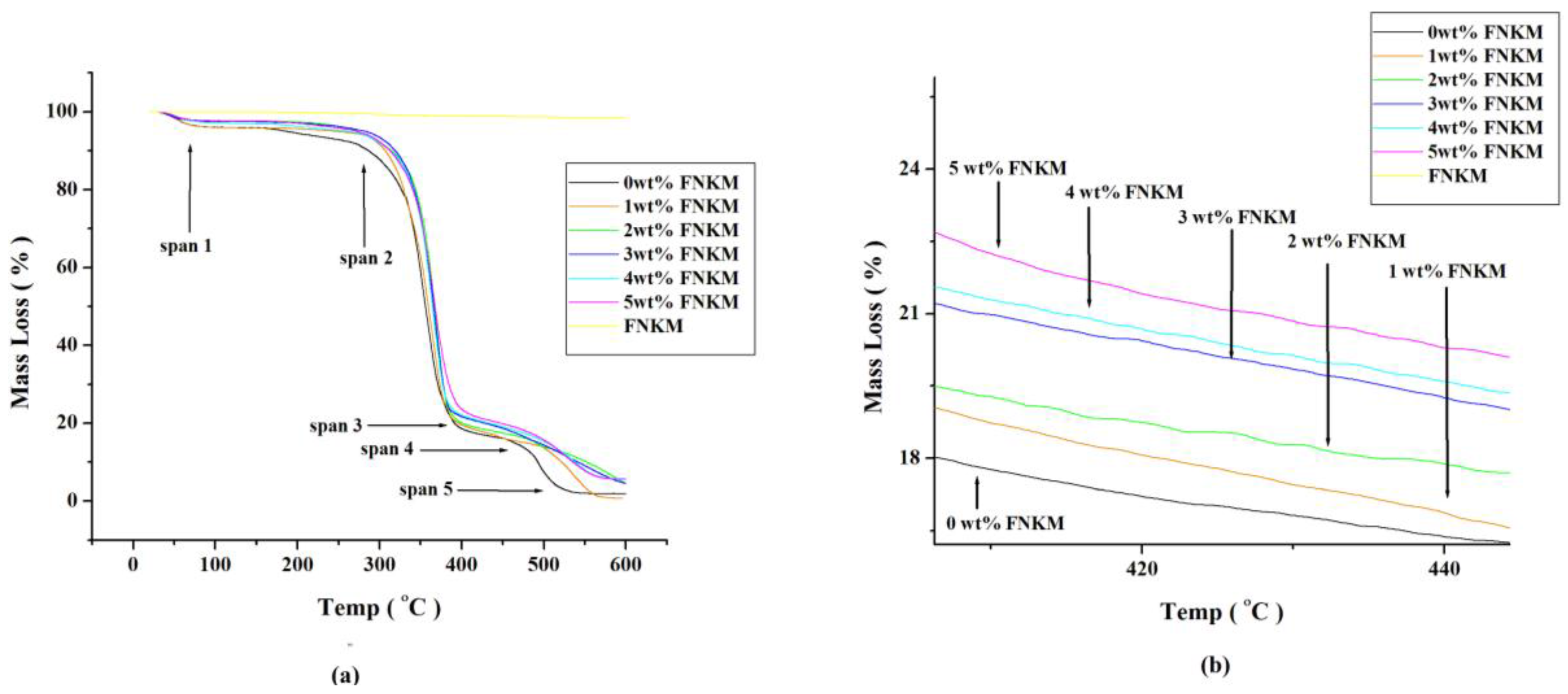
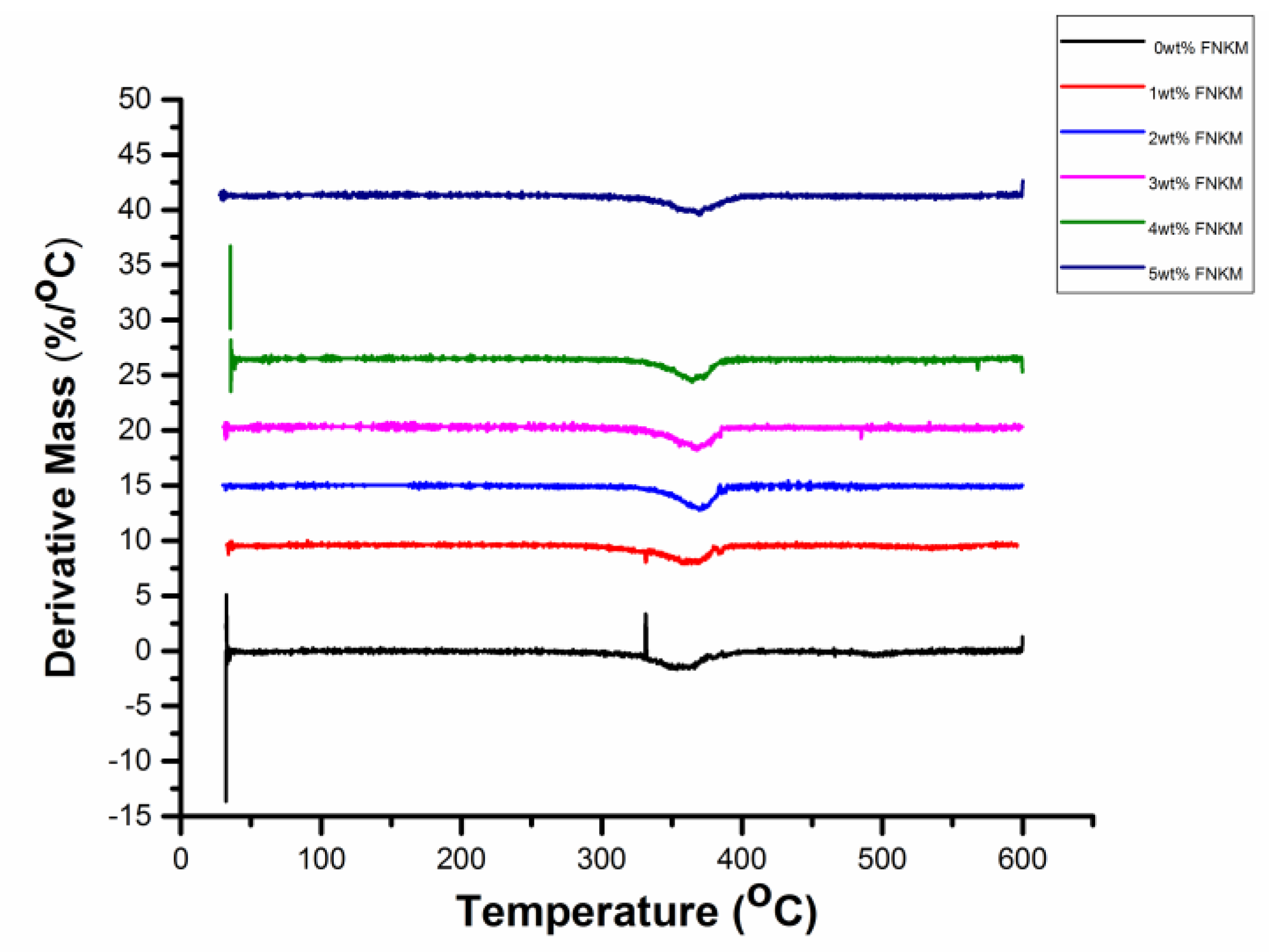
2.3. Thermo-Gravimetric/Differential Thermal Analyses (TGA/DTA)
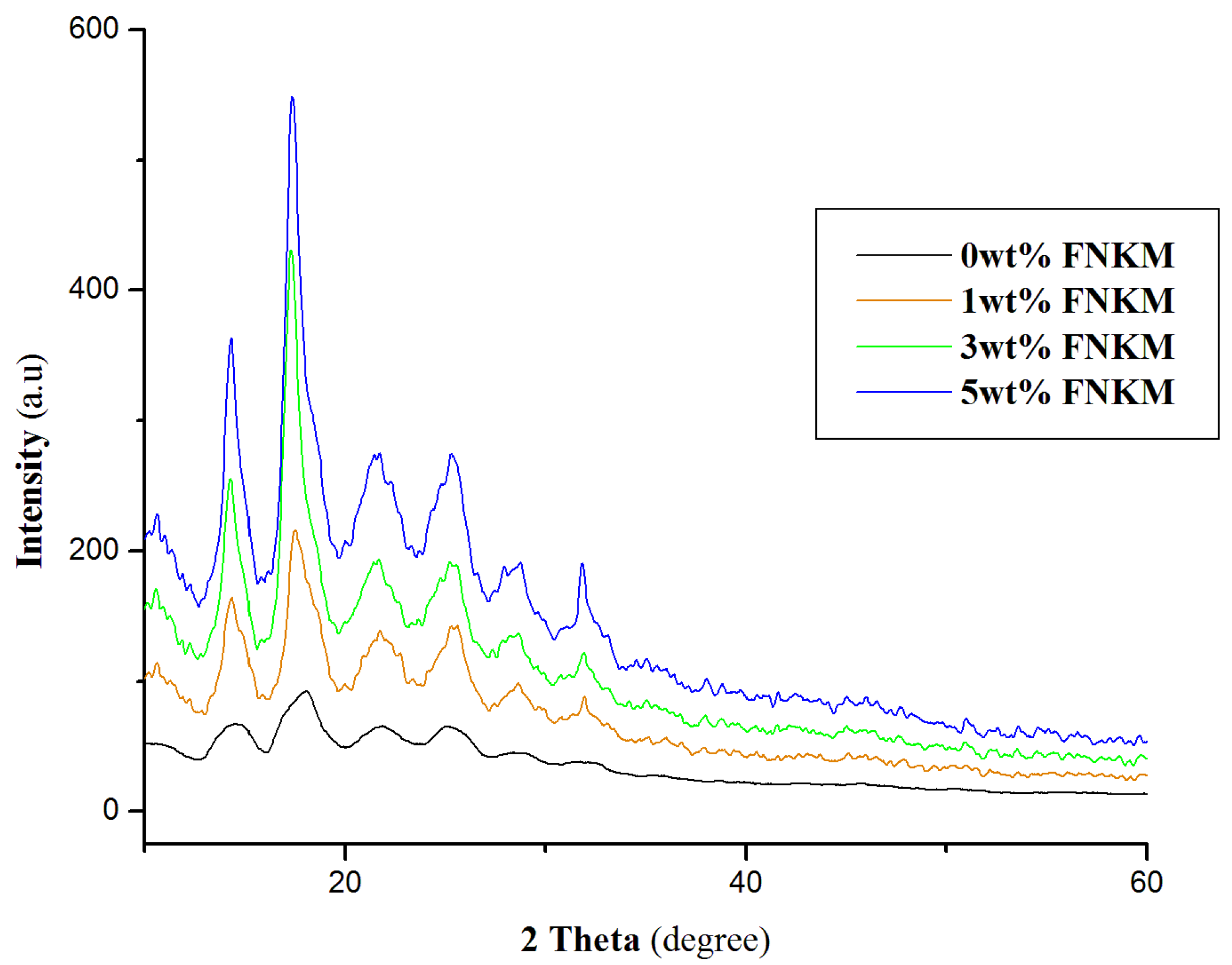
2.4. XRD Analysis
2.5. Membrane Performance
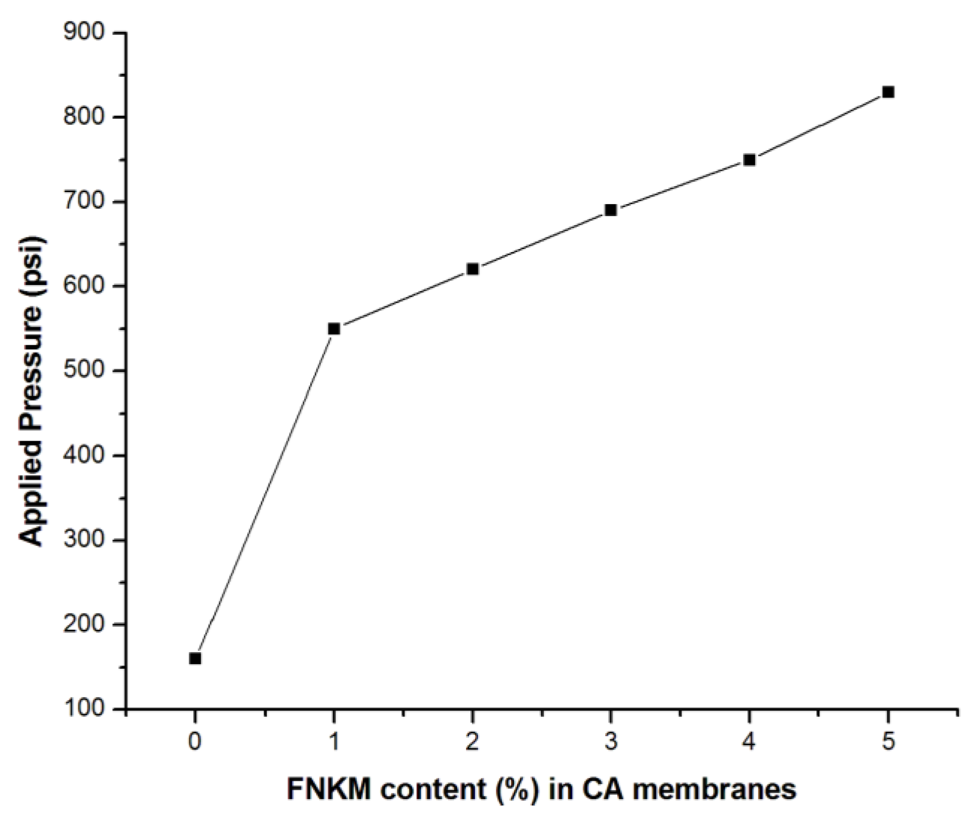
2.5.1. Applied Pressure vs. FNKM Content (%)
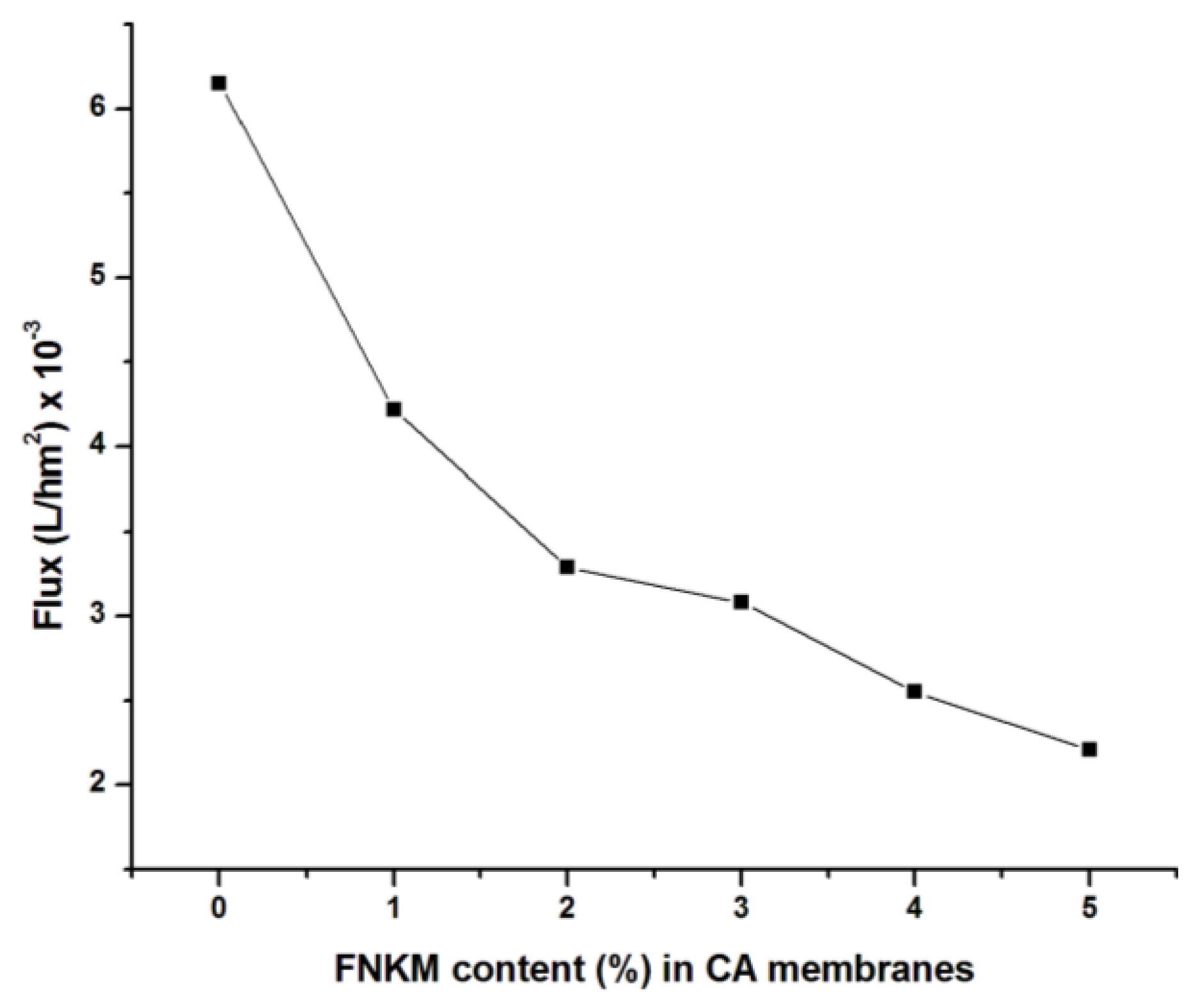
2.5.2. Flux vs. FNKM Content (%) in CA Membranes
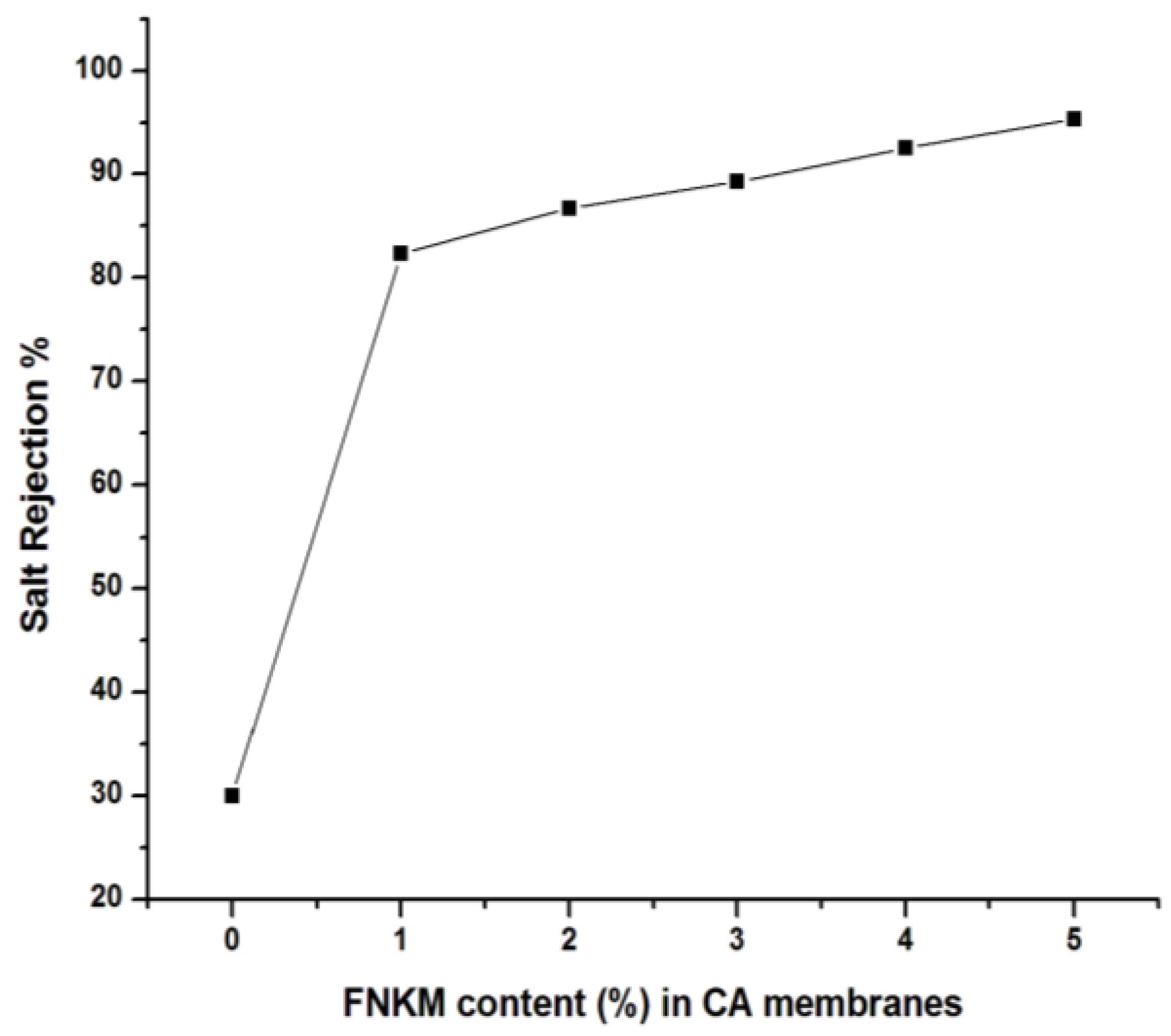
2.5.3. Salt Rejection vs. FNKM Content (%) in CA Membranes
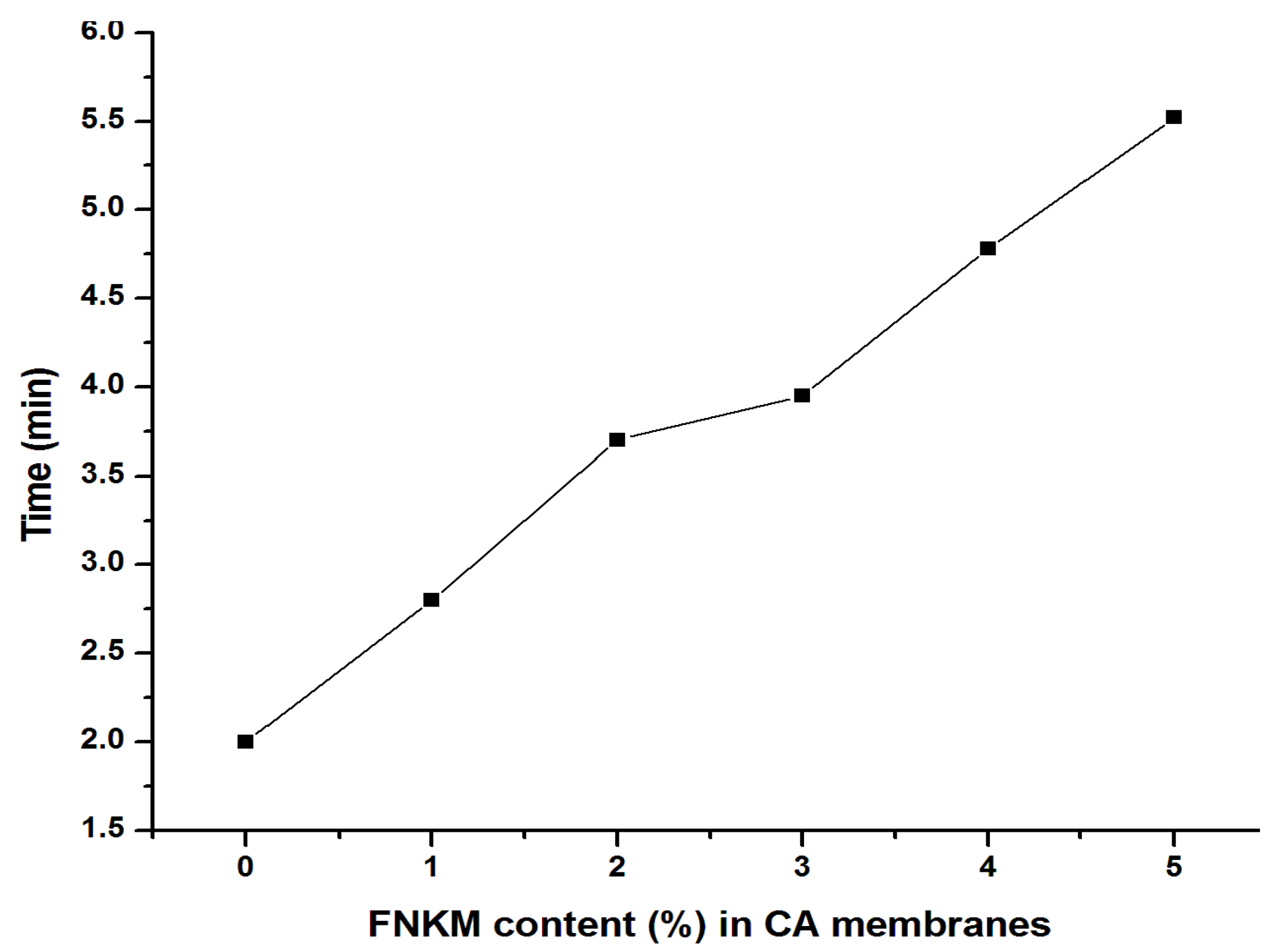
2.5.4. Time vs. FNKM Content (%) in CA Membranes
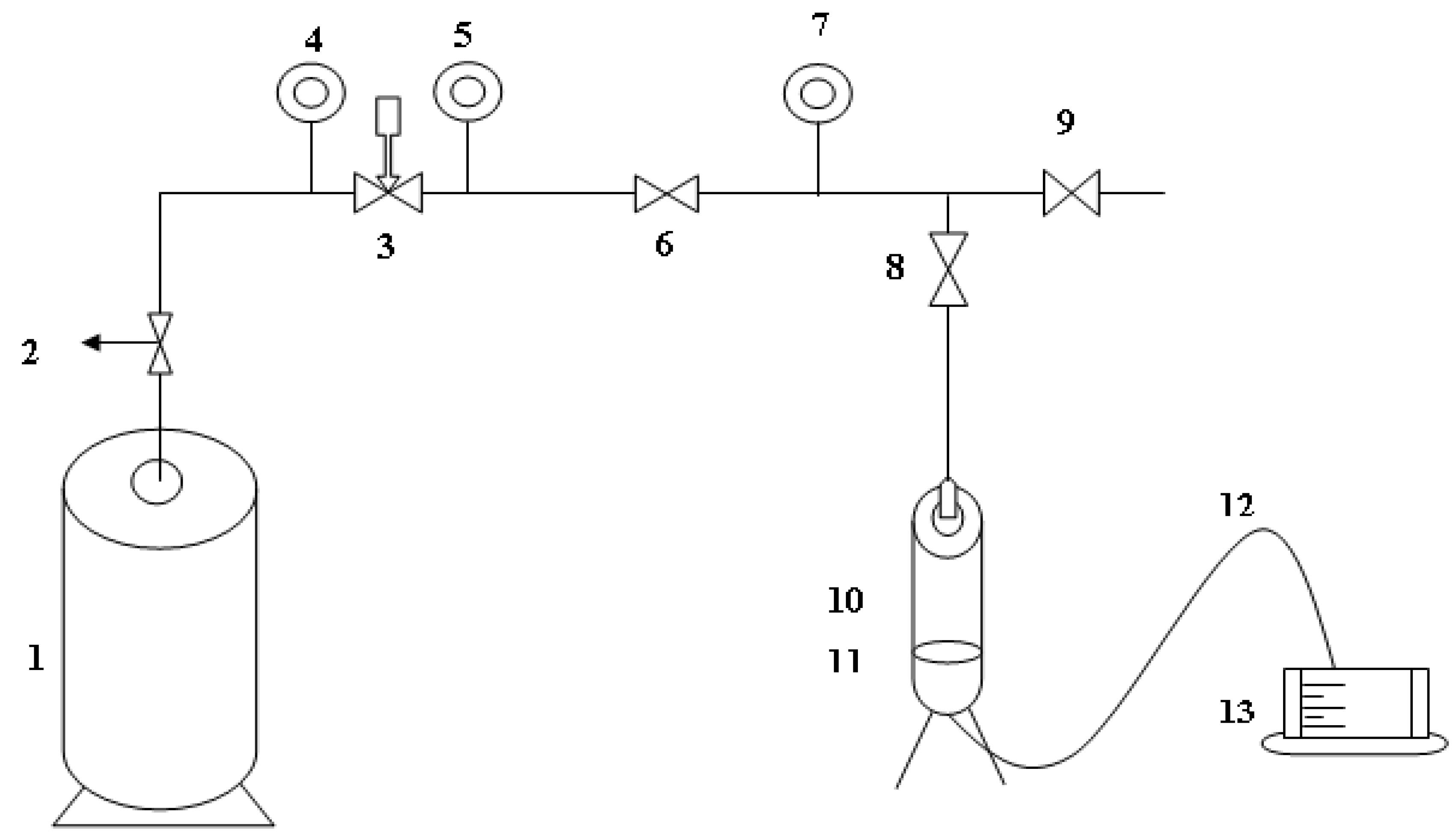
3. Experimentation
3.1. Materials and Methods
3.1.1. Materials
3.1.2. Fabrication Method
3.2. Characterization
4. Conclusions
Acknowledgments
Author Contributions
Conflicts of Interest
References
- Ashraf, M.A.; Maah, M.J.; Qureshi, A.K.; Gharibrez, M.; Yusoff, I. Synthetic polymer composite membrane for the desalination of saline water. Desalin. Water Treat. 2013, 51, 3650–3661. [Google Scholar] [CrossRef]
- Naghsh, M.; Sadeghi, M.; Moheb, A.; Chenar, M.P.; Mohagheghian, M. Separation of ethylene/ethane and propylene/propane by cellulose acetate–silica nanocomposite membranes. J. Membr. Sci. 2012, 423–424, 97–106. [Google Scholar] [CrossRef]
- Idris, A.; Yet, L.K. The effect of different molecular weight PEG additives on cellulose acetate asymmetric dialysis membrane performance. J. Membr. Sci. 2006, 280, 920–927. [Google Scholar] [CrossRef]
- Li, J.; Wang, S.; Nagai, K.; Nakagawa, T.; Mau, A.W.-H. Effect of polyethyleneglycol (PEG) on gas permeabilities and permselectivities in its cellulose acetate (CA) blend membranes. J. Membr. Sci. 1998, 138, 143–152. [Google Scholar] [CrossRef]
- Moghadassi, A.R.; Rajabi, Z.; Hosseini, S.M.; Mohammadi, M. Fabrication and modification of cellulose acetate based mixed matrix membrane: Gas separation and physical properties. J. Ind. Eng. Chem. 2014, 20, 1050–1060. [Google Scholar] [CrossRef]
- Nam, B.-U.; Min, K.-D.; Son, Y. Investigation of the nanostructure, thermal stability, and mechanical properties of polylactic acid/cellulose acetate butyrate/clay nanocomposites. Mater. Lett. 2015, 150, 118–121. [Google Scholar] [CrossRef]
- Filho, G.R.; Monteiro, D.S.; da Silva Meireles, C. Synthesis and characterization of cellulose acetate produced from recycled newspaper. Carbohydr. Polym. 2008, 73, 74–82. [Google Scholar] [CrossRef]
- Rahimpour, A.; Jahanshahi, M.; Mollahosseini, A.; Rajaeian, B. Structural and performance properties of UV-assisted TiO2 deposited nano-composite PVDF/SPES membranes. Desalination 2012, 285, 31–38. [Google Scholar] [CrossRef]
- Van de Witte, P.; Dijkstra, P.J.; van den Berg, J.W.A.; Feijen, J. Phase separation processes in polymer solutions in relation to membrane formation. J. Membr. Sci. 1996, 117, 1–31. [Google Scholar] [CrossRef]
- Abdel-Naby, A.S.; Al-Ghamdi, A.A. Chemical modification of cellulose acetate by N-(phenyl amino) maleimides: Characterization and properties. Int. J. Biol. Macromol. 2014, 68, 21–27. [Google Scholar] [CrossRef] [PubMed]
- Yuwawech, K.; Wootthikanokkhan, J.; Tanpichai, S. Enhancement of thermal, mechanical and barrier properties of EVA solar cell encapsulating films by reinforcing with esterified cellulose nanofibers. Polym. Test. 2015, 48, 12–22. [Google Scholar] [CrossRef]
- Abedini, R.; Mahmoud Mousavi, S.M.; Aminzadeh, R. A novel cellulose acetate (CA) membrane using TiO2 nanoparticles: Preparation, characterization and permeation study. Desalination 2011, 277, 40–45. [Google Scholar] [CrossRef]
- Zodrow, K.; Brunet, L.; Mahendra, S.; Li, D.; Zhang, A.; Li, Q.; Alvarez, P.J. Polysulfone ultrafiltration membranes impregnated with silver nanoparticles show improved biofouling resistance and virus removal. J. Water Res. 2009, 43, 715–723. [Google Scholar] [CrossRef] [PubMed]
- Rahimpour, A.; Jahanshahi, M.; Khalili, S.; Mollahosseini, A.; Zirepour, A.; Rajaeian, B. Novel functionalized carbon nanotubes for improving the surface properties and performance of polyethersulfone (PES) membrane. Desalination 2012, 286, 99–107. [Google Scholar] [CrossRef]
- Badawi, N.E.; Ramadan, A.R.; Esawi, A.M.K.; El-Morsi, M. Novel carbon nanotube–cellulose acetate nanocomposite membranes for water filtration applications. Desalination 2014, 344, 79–85. [Google Scholar] [CrossRef]
- Nezam El-Din, L.A.; El-Gendi, A.; Ismail, N.; Abed, K.A.; Ahmed, A.I. Evaluation of cellulose acetate membrane with carbon nanotubes additives. J. Ind. Eng. Chem. 2015, 26, 259–264. [Google Scholar] [CrossRef]
- Favvas, E.P.; Nitodas, S.F.; Stefopoulos, A.A.; Papageorgiou, S.K.; Stefanopoulos, K.L.; Mitropoulos, A.C. High purity multi-walled carbon nanotubes: Preparation, characterization and performance as filler materials in co-polyimide hollow fiber membranes. Sep. Purif. Technol. 2014, 122, 262–269. [Google Scholar] [CrossRef]
- Luo, Y.; Wang, S.; Shen, M.; Qi, R.; Fanga, Y.; Guo, R.; Cai, H.; Cao, X.; Tomás, H.; Zhu, M.; et al. Carbon nanotube-incorporated multilayered cellulose acetate nanofibers for tissue engineering applications. Carbohydr. Polym. 2013, 91, 419–427. [Google Scholar] [CrossRef] [PubMed]
- Ahmad, A.L.; Jawad, Z.A.; Low, S.C.; Zein, S.H.S. A cellulose acetate/multi-walled carbon nanotube mixed matrix membrane for CO2/N2 separation. J. Membr. Sci. 2014, 451, 55–66. [Google Scholar] [CrossRef]
- Celik, E.; Park, H.; Choi, H.; Choi, H. Carbon nanotube blended polyethersulfone membranes for fouling control in water treatment. Water Res. 2011, 45, 274–282. [Google Scholar] [CrossRef] [PubMed]
- Choi, J.-H.; Jegal, J.; Kim, W.-N. Fabrication and characterization of multi-walled carbon nanotubes/polymer blend membranes. J. Membr. Sci. 2006, 284, 406–415. [Google Scholar] [CrossRef]
- Feng, Y.; Wang, K.; Davies, C.H.J.; Wang, H. Carbon Nanotube/Alumina/Polyethersulfone Hybrid Hollow Fiber Membranes with Enhanced Mechanical and Anti-Fouling Properties. Nanomaterials 2015, 5, 1366–1378. [Google Scholar] [CrossRef]
- Shawky, H.A.; Chae, S.-R.; Lin, S.; Wiesner, M.R. Synthesis and characterization of a carbon nanotube/polymer nanocomposite membrane for water treatment. Desalination 2011, 272, 46–50. [Google Scholar] [CrossRef]
- Awasthi, K.K.; John, P.J.; Awasthi, A.; Awasthi, K. Multi walled carbon nano tubes induced hepatotoxicity in Swiss albino mice. Micron 2013, 44, 359–364. [Google Scholar] [CrossRef] [PubMed]
- Lucia, U.C.; Delia, C.; Aureliano, C.; Maria, F.A.; Raffaele, M.; Buresti, G.; Casciardi, S.; Iavicoli, S. Cytotoxic, Genotoxic and Proinflammatory Response of Human Bronchial Cells to Pristine and Functionalized MWCNTs. Mater. Today Proc. 2015, 2, 126–133. [Google Scholar] [CrossRef]
- Firme, C.P., III; Bandaru, P.R. Toxicity issues in the application of carbon nanotubes to biological systems. Nanomedicine Nanotechnol. Biol. Med. 2010, 6, 245–256. [Google Scholar] [CrossRef] [PubMed]
- Mahdavi, H.; Shahalizade, T. Preparation, characterization and performance study of cellulose acetate membranes modified by aliphatic hyper branched polyester. J. Membr. Sci. 2015, 473, 256–266. [Google Scholar] [CrossRef]
- De Moraes, A.C.; Andrade, P.F.; de Faria, A.F.; Simões, M.B.; Salomão, F.C.C.S.; Barros, E.B.; do Carmo Gonçalves, M.; Alves, O.L. Fabrication of transparent and ultraviolet shielding composite films based on graphene oxide and cellulose acetate. Carbohydr. Polym. 2015, 123, 217–227. [Google Scholar] [CrossRef] [PubMed]
- Kee, C.M.; Idris, A. Permeability performance of different molecular weight cellulose acetate hemodialysis membrane. Sep. Purif. Technol. 2010, 75, 102–113. [Google Scholar] [CrossRef]
- John, A.; Chen, Y.; Kim, J. Synthesis and characterization of cellulose acetate–calcium carbonate hybrid nanocomposite. Compos. Part B 2012, 43, 522–525. [Google Scholar] [CrossRef]
- Worthley, C.H.; Constantopoulos, K.T.; Ginic-Markovic, M.; Pillar, R.J.; Matisons, J.G.; Clarke, S. Surface modification of commercial cellulose acetate membranes using surface-initiated polymerization of 2-hydroxyethyl methacrylate to improve membrane surface biofouling resistance. J. Membr. Sci. 2011, 385–386, 30–39. [Google Scholar] [CrossRef]
- Rathore, B.S.; Sharma, G.; Pathania, D.; Gupta, V.K. Synthesis, characterization and antibacterial activity of cellulose acetate–tin (IV) phosphate nanocomposite. Carbohydr. Polym. 2014, 103, 221–227. [Google Scholar] [CrossRef] [PubMed]
- Zafar, M.; Ali, M.; Khan, S.M.; Jamil, T.; Butt, M.T.Z.B. Effect of additives on the properties and performance of cellulose acetate derivative membranes in the separation of isopropanol/water mixtures. Desalination 2012, 285, 359–365. [Google Scholar] [CrossRef]
- Bose, S.; Das, C. Sawdust: From wood waste to pore-former in the fabrication of ceramic membrane. Ceram. Int. 2015, 41, 4070–4079. [Google Scholar] [CrossRef]
- Ghouil, B.; Harabi, A.; Bouzerara, F.; Boudaira, B.; Guechi, A.; Demir, M.M.; Figoli, A. Development and characterization of tubular composite ceramic membranes using natural alumino-silicates for microfiltration applications. Mater. Charact. 2015, 103, 18–27. [Google Scholar] [CrossRef]
- Ahmad, A.; Waheed, S.; Khan, S.M.; e-Gul, S.; Shafiq, M.; Farooq, M.; Sanaullah, K.; Jamil, T. Effect of silica on the properties of cellulose acetate/polyethylene glycol membranes for reverse osmosis. Desalination 2015, 355, 1–10. [Google Scholar] [CrossRef]
- Wu, C.-S. Characterization of cellulose acetate-reinforced aliphatic–aromatic copolyester composites. Carbohydr. Polym. 2012, 87, 1249–1256. [Google Scholar] [CrossRef]
- Sabir, A.; Shafiq, M.; Islam, A.; Sarwar, A.; Dilshad, M.R.; Shafeeq, A.; Butt, M.T.Z.; Jamil, T. Fabrication of tethered carbon nanotubes in cellulose acetate/polyethylene glycol-400 composite membranes for reverse osmosis. Carbohydr. Polym. 2015, 132, 589–597. [Google Scholar] [CrossRef] [PubMed]


| Sample Name | Wave Number (cm−1) | Chemical Bond | References |
|---|---|---|---|
| 0 and 5 wt % FNKM loaded CA membrane | 3484 | Stretching vibration of –OH exist in CA | [30,31] |
| 2949 | Stretching vibration of –CH, –CH2, –CH3 | [30] | |
| 2890 | Stretching vibration of –CH, –CH2, –CH3 | [30] | |
| 2464 | Stretching vibration of –OH , evident of glycol | [33] | |
| 2122 | Stretching vibration of C≡C | [33] | |
| 1747 | Stretching vibration of carboxyl group of CA, C=0, Strong peak due to stretching mode of ester group | [30,32] | |
| 1638 | Strongly bonded –OH group in the matrix | [32] | |
| 1430 | –CH2 symmetric, or –CH3 asymmetric stretching mode | [30] | |
| 1374 | C–C bond stretching | [33] | |
| 1230 | C–O bond, contributed by acetate group | [29,31] | |
| 1160 | C–O–C bridge anti-symmetric stretching | [28,31] | |
| 1045 | C–O Stretching mode; contributed by acetate group | [29] | |
| 906 | Asymmetric ring stretching mode | [30] | |
| 5 wt % FNKM loaded membrane | 2266 | Si–O–CH3 molecules attached with FNKM | [35] |
| 1255 | C–O stretch bond | [34] | |
| FNKM | 3420 | Si–CH3 stretching mode | [35] |
| 1638 | C–C chiral structure of MWCNTs | [34] | |
| 1200 | Si–O–CH3 vibration | [34,35] | |
| 904 | –CH3 attached with silicon | [28,29,30] | |
| 505 | Si–O– silicon moiety attachment | [30,31,35] | |
| 465 | Si–O– silicon moiety attachment | [30,31,35] | |
| 412 | Si–O– silicon moiety attachment | [30,31,35] |
| FNKM Content (%) | Applied Pressure (psi) | Flux × 10−3 (L/hm2) | Salt Rejection (%) | Salt Passage (%) | Time (min) |
|---|---|---|---|---|---|
| 0 | 160 | 6.15 | 30 | 70 | 2 |
| 1 | 550 | 4.22 | 82.3 | 17.7 | 2.89 |
| 2 | 620 | 3.29 | 86.7 | 13.3 | 3.7 |
| 3 | 690 | 3.08 | 89.25 | 10.75 | 3.95 |
| 4 | 750 | 2.55 | 92.5 | 7.5 | 4.78 |
| 5 | 830 | 2.20 | 95.35 | 4.65 | 5.52 |
| Membrane | Solvent | Matrix Polymer | Additive |
|---|---|---|---|
| FNKM wt % | Acetones:CA/PEG (v/w) | CA:PEG (w/w) | FNKM:(CA/PEG) |
| CA/PEG/FNKM 0 wt % | 10:1 | 72:27 | 0% |
| CA/PEG/FNKM 1 wt % | 10:1 | 72:27 | 1% |
| CA/PEG/FNKM 2 wt % | 10:1 | 72:27 | 2% |
| CA/PEG/FNKM 3 wt % | 10:1 | 72:27 | 3% |
| CA/PEG/FNKM 4 wt % | 10:1 | 72:27 | 4% |
| CA/PEG/FNKM 5 wt % | 10:1 | 72:27 | 5% |
© 2016 by the authors; licensee MDPI, Basel, Switzerland. This article is an open access article distributed under the terms and conditions of the Creative Commons Attribution (CC-BY) license (http://creativecommons.org/licenses/by/4.0/).
Share and Cite
Afzal, A.; Rafique, M.S.; Iqbal, N.; Qaiser, A.A.; Anwar, A.W.; Iqbal, S.S. Synergistic Effect of Functionalized Nanokaolin Decorated MWCNTs on the Performance of Cellulose Acetate (CA) Membranes Spectacular. Nanomaterials 2016, 6, 79. https://doi.org/10.3390/nano6040079
Afzal A, Rafique MS, Iqbal N, Qaiser AA, Anwar AW, Iqbal SS. Synergistic Effect of Functionalized Nanokaolin Decorated MWCNTs on the Performance of Cellulose Acetate (CA) Membranes Spectacular. Nanomaterials. 2016; 6(4):79. https://doi.org/10.3390/nano6040079
Chicago/Turabian StyleAfzal, Amina, Muhammad Shahid Rafique, Nadeem Iqbal, Asif Ali Qaiser, Abdul Waheed Anwar, and Sadia Sagar Iqbal. 2016. "Synergistic Effect of Functionalized Nanokaolin Decorated MWCNTs on the Performance of Cellulose Acetate (CA) Membranes Spectacular" Nanomaterials 6, no. 4: 79. https://doi.org/10.3390/nano6040079