
A Microchip for High-Throughput Axon Growth Drug Screening


Abstract
:
1. Introduction
2. Materials and Methods
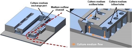
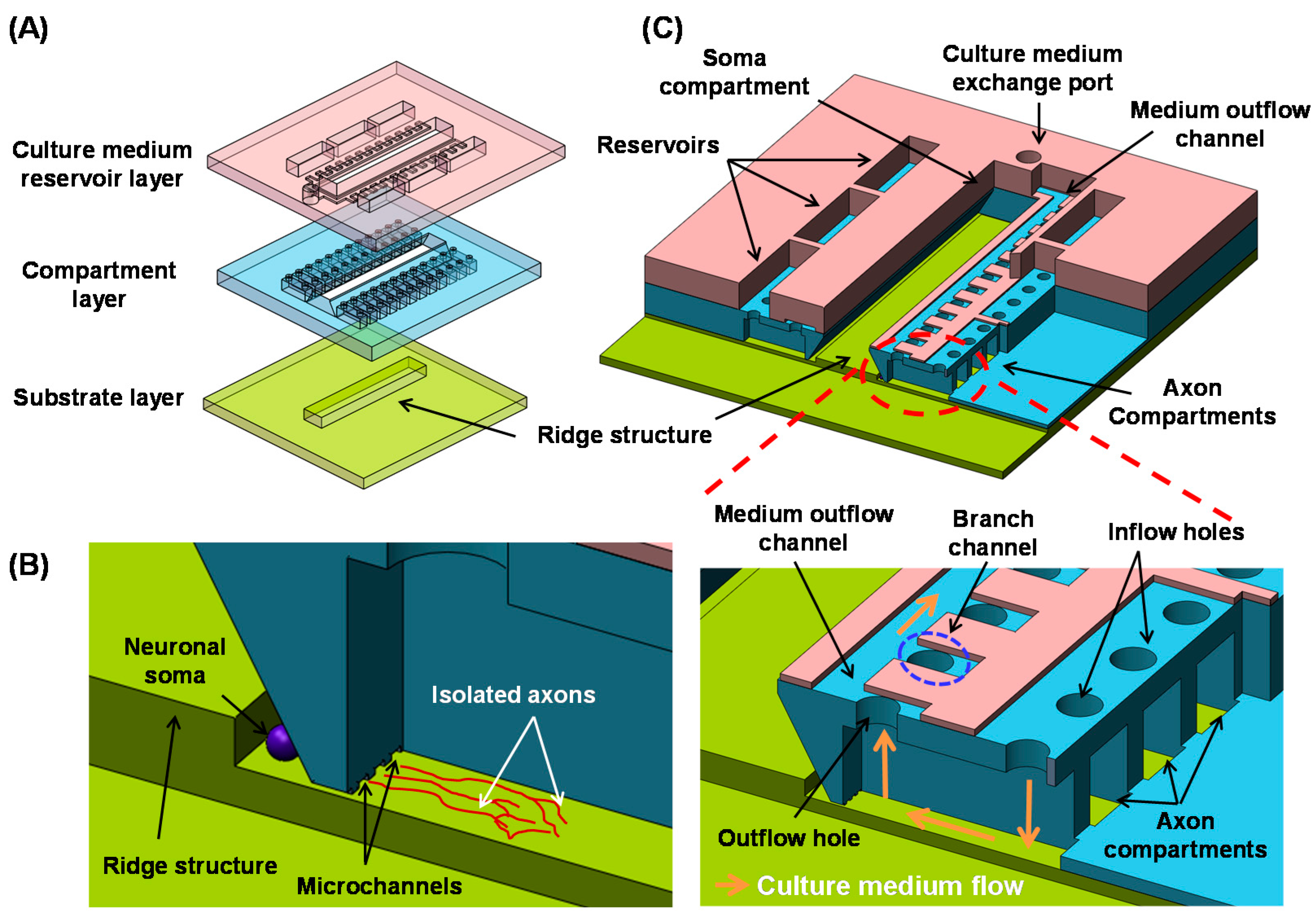
2.1. Design
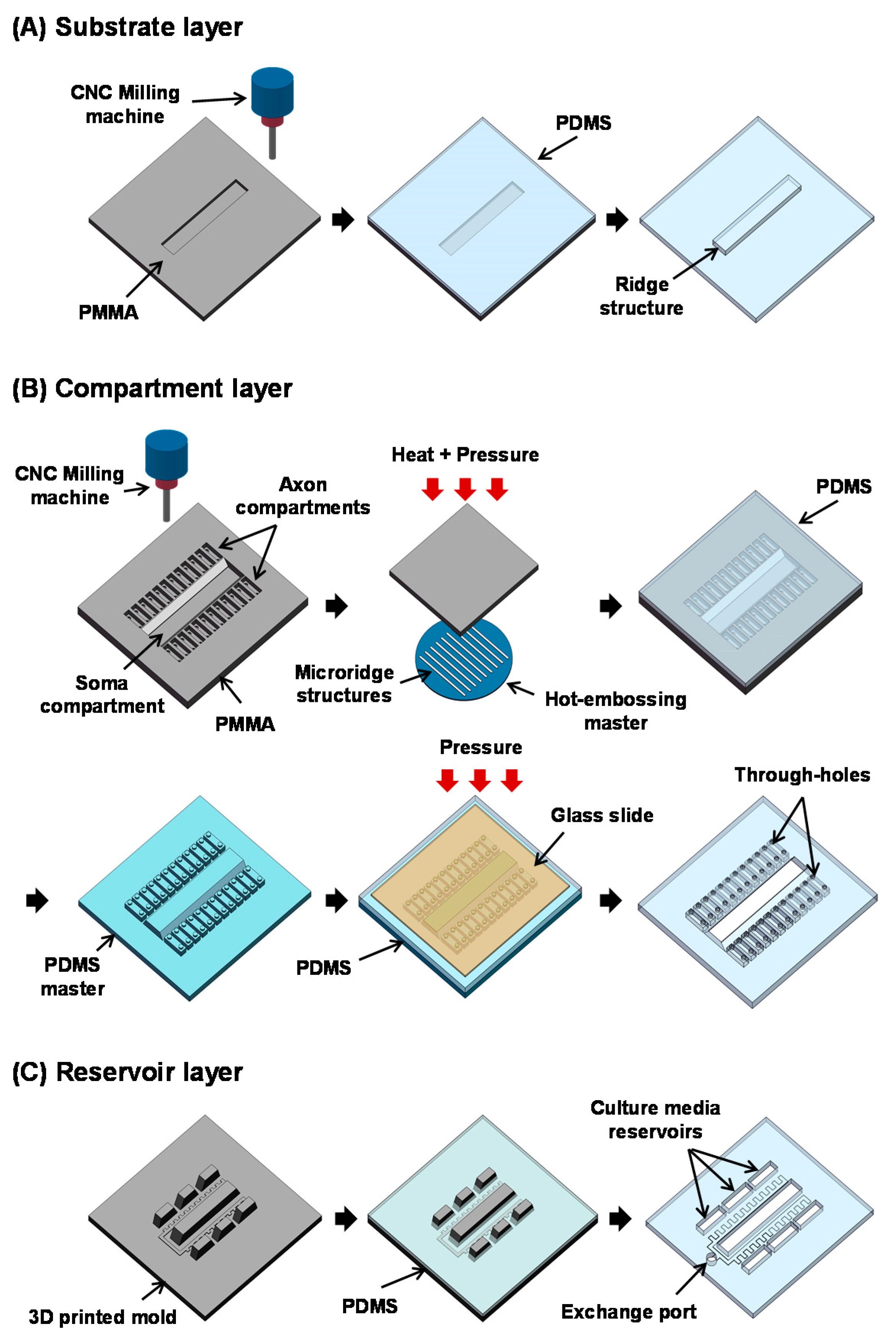
2.2. Fabrication
2.3. Tissue Dissociation and Cell Preparation
2.4. Microchip Cell Culture
2.5. Localized Biomolecular Treatment
2.6. Imaging
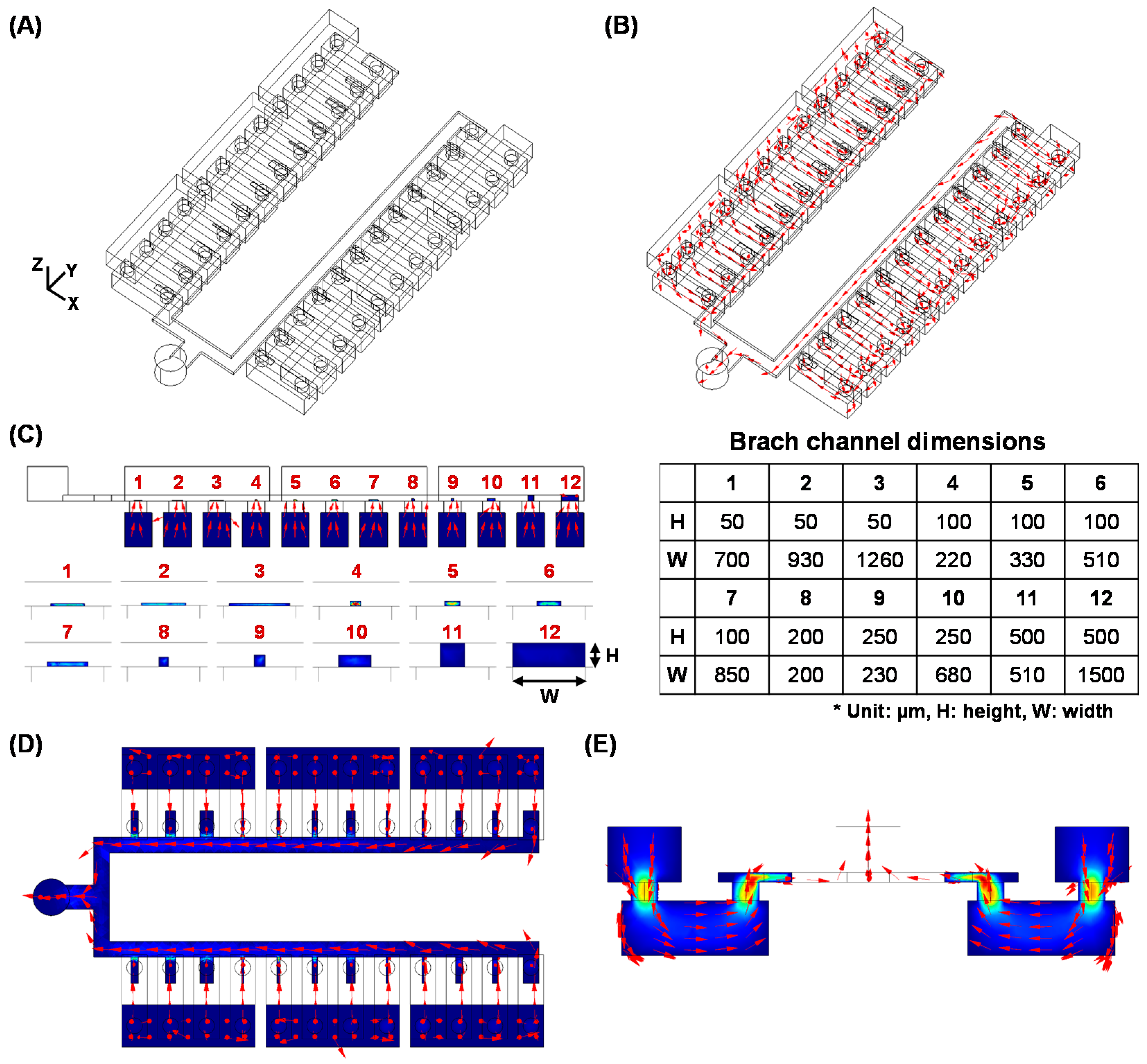
2.7. Fluidic Simulation
3. Results and Discussion
4. Conclusions
Supplementary Materials
Acknowledgments
Author Contributions
Conflicts of Interest
Abbreviations
| CNS | Central nervous system |
| PNS | Peripheral nervous system |
| MAG | Myelin-associated glycoprotein |
| OMgp | Oligodendrocyte myelin glycoprotein |
| PDMS | Poly(dimethylsiloxane) |
| CNC | Computer numerically controlled |
| PMMA | Poly(methyl methacrylate) |
| AM | Acetoxymethyl |
| SEM | Scanning electron microscope |
| IPA | Isopropyl alcohol |
| DI water | Deionized water |
| E16 | Embryonic day 16 |
| DIV | Days in vitro |
| CSPG | Chondroitin sulfate proteoglycan |
| PBS | Phosphate buffered saline |
| FEM | Finite element method |
References
- Qiu, J.; Cai, D.; Filbin, M. Glial inhibition of nerve regeneration in the mature mammalian CNS. Glia 2000, 29, 166–174. [Google Scholar] [CrossRef]
- Fitch, M.; Silver, J. CNS injury, glial scars, and inflammation: Inhibitory extracellular matrices and regeneration failure. Exp. Neurol. 2008, 209, 294–301. [Google Scholar] [CrossRef] [PubMed]
- Harel, N.; Strittmatter, S. Can regenerating axons recapitulate developmental guidance during recovery from spinal cord injury? Nat. Rev. Neurosci. 2006, 7, 603–616. [Google Scholar] [CrossRef] [PubMed]
- Yiu, G.; He, Z. Glial inhibition of CNS axon regeneration. Nat. Rev. Neurosci. 2006, 7, 617–627. [Google Scholar] [CrossRef] [PubMed]
- Park, K.; Liu, K.; Hu, Y.; Smith, P.; Wang, C.; Cai, B.; Xu, B.; Connolly, L.; Kramvis, I.; Sahin, M. Promoting axon regeneration in the adult CNS by modulation of the PTEN/mTOR pathway. Science 2008, 322, 963–966. [Google Scholar] [CrossRef] [PubMed]
- Goldberg, J.L.; Espinosa, J.S.; Xu, Y.; Davidson, N.; Kovacs, G.T.; Barres, B.A. Retinal ganglion cells do not extend axons by default: Promotion by neurotrophic signaling and electrical activity. Neuron 2002, 33, 689–702. [Google Scholar] [CrossRef]
- Goldberg, J.L.; Klassen, M.P.; Hua, Y.; Barres, B.A. Amacrine-signaled loss of intrinsic axon growth ability by retinal ganglion cells. Science 2002, 296, 1860–1864. [Google Scholar] [CrossRef] [PubMed]
- Hartikka, J.; Hefti, F. Development of septal cholinergic neurons in culture: Plating density and glial cells modulate effects of NGF on survival, fiber growth, and expression of transmitter-specific enzymes. J. Neurosci. 1988, 8, 2967–2985. [Google Scholar] [PubMed]
- Brewer, G.; Torricelli, J.; Evege, E.; Price, P. Optimized survival of hippocampal neurons in B27-supplemented neurobasal™, a new serum-free medium combination. J. Neurosci. Res. 1993, 35, 567–576. [Google Scholar] [CrossRef] [PubMed]
- Ito, D.; Tamate, H.; Nagayama, M.; Uchida, T.; Kudoh, S.; Gohara, K. Minimum neuron density for synchronized bursts in a rat cortical culture on multi-electrode arrays. Neuroscience 2010, 171, 50–61. [Google Scholar] [CrossRef] [PubMed]
- Robert, F.; Cloix, J.-F.; Hevor, T. Ultrastructural characterization of rat neurons in primary culture. Neuroscience 2012, 200, 248–260. [Google Scholar] [CrossRef] [PubMed]
- Campenot, R.B. Local control of neurite development by nerve growth factor. Proc. Natl. Acad. Sci. USA 1977, 74, 4516–4519. [Google Scholar] [CrossRef] [PubMed]
- Ishibashi, T.; Dakin, K.A.; Stevens, B.; Lee, P.R.; Kozlov, S.V.; Stewart, C.L.; Fields, R.D. Astrocytes promote myelination in response to electrical impulses. Neuron 2006, 49, 823–832. [Google Scholar] [CrossRef] [PubMed]
- Ng, B.K.; Chen, L.; Mandemakers, W.; Cosgaya, J.M.; Chan, J.R. Anterograde transport and secretion of brain-derived neurotrophic factor along sensory axons promote schwann cell myelination. J. Neurosci. 2007, 27, 7597–7603. [Google Scholar] [CrossRef] [PubMed]
- Taylor, A.M.; Blurton-Jones, M.; Rhee, S.W.; Cribbs, D.H.; Cotman, C.W.; Jeon, N.L. A microfluidic culture platforms for CNS axonal injury, regeneration and transport. Nat. Methods 2005, 2, 599–605. [Google Scholar] [CrossRef] [PubMed]
- Shi, M.; Majumdar, D.; Gao, Y.; Brewer, B.M.; Goodwin, C.R.; McLean, J.A.; Li, D.; Webb, D.J. Glia co-culture with neurons in microfluidic platforms promotes the formation and stabilization of synaptic contacts. Lab Chip 2013, 13, 3008–3021. [Google Scholar] [CrossRef] [PubMed]
- Yamaoka, S.; Ito, N.; Ohka, S.; Kaneda, S.; Nakamura, H.; Agari, T.; Masatani, T.; Nakagawa, K.; Okada, K.; Okadera, K. Involvement of rabies virus phosphoprotein gene in neuroinvasiveness. J. Virol. 2013, 87, 12327–12338. [Google Scholar] [CrossRef] [PubMed]
- Kunze, A.; Lengacher, S.; Dirren, E.; Aebischer, P.; Magistretti, P.J.; Renaud, P. Astrocyte-neuron co-culture on microchips based on the model of SOD mutation to mimic ALS. Integr. Biol. 2013, 5, 964–975. [Google Scholar] [CrossRef] [PubMed]
- Shi, P.; Scott, M.A.; Ghosh, B.; Wan, D.; Wissner-Gross, Z.; Mazitschek, R.; Haggarty, S.J.; Yanik, M.F. Synapse microarray identification of small molecules that enhance synaptogenesis. Nat. Commun. 2011, 2, 510. [Google Scholar] [CrossRef] [PubMed]
- Kilinc, D.; Peyrin, J.M.; Soubeyre, V.; Magnifico, S.; Saias, L.; Viovy, J.L.; Brugg, B. Wallerian-like degeneration of central neurons after synchronized and geometrically registered mass axotomy in a three-compartmental microfluidic chip. Neurotox. Res. 2011, 19, 149–161. [Google Scholar] [CrossRef] [PubMed]
- Hur, E.M.; Yang, I.H.; Kim, D.H.; Byun, J.; Levchenko, A.; Thakor, N.; Zhou, F.-Q. Engineering neuronal growth cones to promote axon regeneration over inhibitory molecules. Proc. Natl. Acad. Sci. USA 2011, 108, 5057–5062. [Google Scholar] [CrossRef] [PubMed]
- Park, J.W.; Vahidi, B.; Kim, H.J.; Rhee, S.W.; Jeon, N.L. Quantitative analysis of CNS axon regeneration using a microfluidic neuron culture device. Biochip J. 2008, 2, 44–51. [Google Scholar]
- Kim, Y.; Karthikeyan, K.; Chirvi, S.; Davé, D. Neuro-optical microfluidic platform to study injury and regeneration of single axons. Lab Chip 2009, 9, 2576–2581. [Google Scholar] [CrossRef] [PubMed]
- Hosmane, S.; Fournier, A.; Wright, R.; Rajbhandari, L.; Siddique, R.; Yang, I.H.; Ramesh, K.; Venkatesan, A.; Thakor, N. Valve-based microfluidic compression platform: Single axon injury and regrowth. Lab Chip 2011, 11, 3888–3895. [Google Scholar] [CrossRef] [PubMed]
- Yap, Y.C.; Dickson, T.C.; King, A.E.; Breadmore, M.C.; Guijt, R.M. Microfluidic culture platform for studying neuronal response to mild to very mild axonal stretch injurya. Biomicrofluidics 2014, 8, 044110. [Google Scholar] [CrossRef] [PubMed]
- Park, J.; Koito, H.; Li, J.; Han, A. Multi-compartment neuron-glia co-culture platform for localized cns axon-glia interaction study. Lab Chip 2012, 12, 3296–3304. [Google Scholar] [CrossRef] [PubMed]
- Park, J.; Koito, H.; Li, J.; Han, A. Microfluidic compartmentalized co-culture platform for CNS axon myelination research. Biomed. Microdevices 2009, 11, 1145–1153. [Google Scholar] [CrossRef] [PubMed]
- Park, J.; Li, J.; Han, A. Micro-macro hybrid soft-lithography master (MMHSM) fabrication for lab-on-a-chip applications. Biomed. Microdevices 2010, 12, 345–351. [Google Scholar] [CrossRef] [PubMed]
- Cho, Y.H.; Park, J.; Park, H.; Cheng, X.; Kim, B.; Han, A. Fabrication of high-aspect-ratio polymer nanochannels using a novel Si nanoimprint mold and solvent-assisted sealing. Microfluid. Nanofluid. 2010, 9, 163–170. [Google Scholar] [CrossRef]
- Jo, B.H.; Van Lerberghe, L.M.; Motsegood, K.M.; Beebe, D.J. Three-dimensional micro-channel fabrication in polydimethylsiloxane (PDMS) elastomer. J. Microelectromech. Syst. 2000, 9, 76–81. [Google Scholar] [CrossRef]
- Koito, H.; Li, J. Preparation of rat brain aggregate cultures for neuron and glia development studies. J. Vis. Exp. 2009, 31, e1304. [Google Scholar] [CrossRef] [PubMed]
- Park, J.W.; Vahidi, B.; Taylor, A.; Rhee, S.W.; Jeon, N.L. Microfluidic culture platform for neuroscience research. Nat. Protoc. 2006, 1, 2128–2136. [Google Scholar] [CrossRef] [PubMed]
- Hengst, U.; Deglincerti, A.; Kim, H.; Jeon, N.; Jaffrey, S. Axonal elongation triggered by stimulus-induced local translation of a polarity complex protein. Nat. Cell Biol. 2009, 11, 1024–1030. [Google Scholar] [CrossRef] [PubMed]
- Taylor, A.; Dieterich, D.; Ito, H.; Kim, S.; Schuman, E. Microfluidic local perfusion chambers for the visualization and manipulation of synapses. Neuron 2010, 66, 57–68. [Google Scholar] [CrossRef] [PubMed]
- Dinh, N.D.; Chiang, Y.Y.; Hardelauf, H.; Baumann, J.; Jackson, E.; Waide, S.; Sisnaiske, J.; Frimat, J.P.; van Thriel, C.; Janasek, D.; et al. Microfluidic construction of minimalistic neuronal co-cultures. Lab Chip 2013, 13, 1402–1412. [Google Scholar] [CrossRef] [PubMed]
- Tong, Z.; Seira, O.; Casas, C.; Reginensi, D.; Homs-Corbera, A.; Samitier, J.; Del Río, J.A. Engineering a functional neuro-muscular junction model in a chip. RSC Adv. 2014, 4, 54788–54797. [Google Scholar] [CrossRef]
- Park, J.; Kim, S.; Park, S.I.; Choe, Y.; Li, J.; Han, A. A microchip for quantitative analysis of CNS axon growth under localized biomolecular treatments. J. Neurosci. Methods 2014, 221, 166–174. [Google Scholar] [CrossRef] [PubMed]
- Lingor, P.; Teusch, N.; Schwarz, K.; Mueller, R.; Mack, H.; Bähr, M.; Mueller, B.K. Inhibition of Rho kinase (ROCK) increases neurite outgrowth on chondroitin sulphate proteoglycan in vitro and axonal regeneration in the adult optic nervein vivo. J. Neurochem. 2007, 103, 181–189. [Google Scholar] [PubMed]
- Wang, H.; Katagiri, Y.; McCann, T.E.; Unsworth, E.; Goldsmith, P.; Yu, Z.X.; Tan, F.; Santiago, L.; Mills, E.M.; Wang, Y. Chondroitin-4-sulfation negatively regulates axonal guidance and growth. J. Cell Sci. 2008, 121, 3083–3091. [Google Scholar] [CrossRef] [PubMed]
- Chen, P.; Xu, B.; Tokranova, N.; Feng, X.; Castracane, J.; Gillis, K.D. Amperometric detection of quantal catecholamine secretion from individual cells on micromachined silicon chips. Anal. Chem. 2003, 75, 513–524. [Google Scholar] [CrossRef]

© 2016 by the authors. Licensee MDPI, Basel, Switzerland. This article is an open access article distributed under the terms and conditions of the Creative Commons Attribution (CC-BY) license ( http://creativecommons.org/licenses/by/4.0/).
Share and Cite
Kim, H.S.; Jeong, S.; Koo, C.; Han, A.; Park, J. A Microchip for High-Throughput Axon Growth Drug Screening. Micromachines 2016, 7, 114. https://doi.org/10.3390/mi7070114
Kim HS, Jeong S, Koo C, Han A, Park J. A Microchip for High-Throughput Axon Growth Drug Screening. Micromachines. 2016; 7(7):114. https://doi.org/10.3390/mi7070114
Chicago/Turabian StyleKim, Hyun Soo, Sehoon Jeong, Chiwan Koo, Arum Han, and Jaewon Park. 2016. "A Microchip for High-Throughput Axon Growth Drug Screening" Micromachines 7, no. 7: 114. https://doi.org/10.3390/mi7070114