Article

Design, Fabrication and Computational Characterization of a 3D Micro-Valve Built by Multi-Photon Polymerization

by
Stratos Galanopoulos
1,2,
Nikoleta Chatzidai
1,2,
Vasileia Melissinaki
1,3,
Alexandros Selimis
1,
Charalampos Schizas
2,
Maria Farsari
1,* and
Dimitris Karalekas
2,*
1
Institute of Electronic Structure and Laser (IESL), Foundation for Research and Technology Hellas (FORTH), Heraklion, Crete GR-70013, Greece
2
Laboratory of Advanced Manufacturing Technologies and Testing, University of Piraeus, Piraeus GR-18534, Greece
3
Department of Physics, University of Crete, Heraklion GR-71003, Greece
*
Authors to whom correspondence should be addressed.
Micromachines 2014, 5(3), 505-514; https://doi.org/10.3390/mi5030505
Submission received: 2 July 2014 / Revised: 24 July 2014 / Accepted: 25 July 2014 / Published: 6 August 2014
(This article belongs to the Special Issue Laser Micro- and Nano- Processing)

Abstract

:
We report on the design, modeling and fabrication by multi-photon polymerization of a complex medical fluidic device. The physical dimensions of the built micro-valve prototype are compared to those of its computer-designed model. Important fabrication issues such as achieving high dimensional resolution and ability to control distortion due to shrinkage are presented and discussed. The operational performance of both multi-photon and CAD-created models under steady blood flow conditions was evaluated and compared through computational fluid dynamics analysis.

1. Introduction

Direct Laser Writing (DLW) by multi-photon polymerization (MPP) is a very promising technique for the fabrication of three-dimensional (3D) structures with sub-micron resolution [1,2]. In particular, when the beam of an ultra-fast (picosecond or femtosecond) laser is tightly focused into the volume of a transparent, photosensitive material, the polymerization process can be initiated by nonlinear multi-photon absorption inside the focal volume. By moving the focused laser beam spot in three dimensions, 3D structures can be fabricated. MPP has unique advantages over other competing technologies, since it allows the accurate fabrication of computer-designed, mm-sized 3D microstructures with resolution beyond the diffraction limit [3,4]. A popular class of materials employed in MPP is specially designed organic-inorganic hybrids prepared with the sol-gel method. Due to their optical transparency, electrochemical inertness, mechanical and optical stability, hybrid materials have found application in biology, medicine, photonics, microfluidics, and micro-electromechanical systems (MEMS) [5,6,7,8].
In recent years, a great deal of research effort has been undertaken to design and develop micro-valves for different fluidic applications [9]. In particular, the development of microfluidic devices supporting physiological blood flow has very stringent design requirements related to the precise control of flow and achieved dimensional accuracy of the fabricated microdevice [9]. There are few examples of the fabrication of micro check valves whose main role is to prohibit the reversal of blood flow in human veins. Schizas et al. [10] have demonstrated the feasibility of fabricating a micro-valve with an internal moving piston rod. Additionally, it was reported that the stair-step effect was evident at some valve locations and that distortion was also evident inside the valve’s rod seat reducing thus the designed interface gap.
In the present paper, we present the design and fabrication of a complex micro-valve conceptual design. The micro-valve prototype was fabricated using the DLW technique and the material used for the fabrication of the micro-valve was an inorganic-organic photosensitive hybrid. Several fabrication tests of the valve were performed with different sets of fabrication parameters in order to accurately reproduce the computer-designed valve. In addition, we evaluate under simulated blood flow both the fabricated micro-valve and its computer-designed model.

2. Design and Fabrication

2.1. Micro-Valve Design

The micro-valve design investigated in this work consists of three parts: the main cylindrical body and the two wings rotating around a cylindrical shaft, as can be seen in Figure 1a (top view). The body of the valve has a cylindrical surface of circular cross section while the wings have a semi-circular shape. The wings can move, under forward fluid flow and close firmly in the case of backward flow, as illustrated in Figure 1b, where the one half of the valve is shown. A non-movable wing has been designed in the body of the valve serving as a mechanical stop against the movement of the other two wings in case of the forward blood flow. The circular part in the inner body of the valve acts as a sealing agent in the case of the backward reverse blood flow. Blood can flow through the valve in the direction from bottom to the top, as depicted in Figure 1b. All parts of the assembly can be readily fabricated in a single step using DLW.
The valve was designed to have an external diameter of 180 μm and a length of 173 μm while its internal diameter was set to be 143 μm. Such values correspond to the venules of the human body [10]. In order to keep the blood flow distortion as lower as possible, special care was taken so that the internal surface of the valve is smooth. The micro-valve was visually characterized using Scanning Electron Microscopy (SEM). Since the internal geometrical characteristics of the artificial micro-valve needed to be visible during SEM evaluation, in addition to fully operational valves, one half and three quarter geometry valves were produced.
Figure 1. Three dimensional computer-aided design of the micro-valve. (a) cross sectional view of the whole micro-valve, and (b) view of the one half of the micro-valve.
Micromachines 05 00505 g001

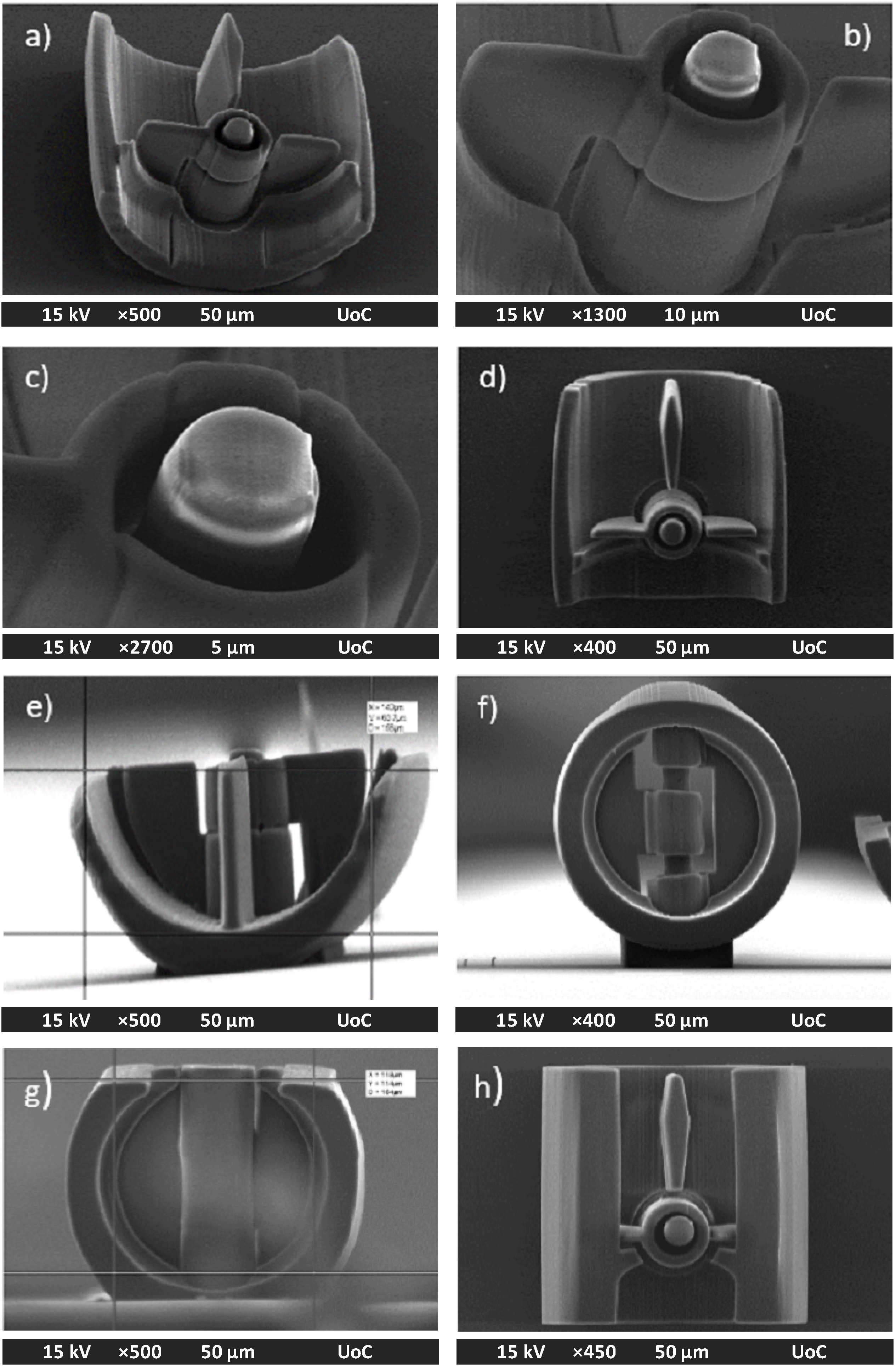
2.2. Micro-Valve Fabrication

The fabrication of 3D structures by DLW has been described by several groups [11,12]. The material used to fabricate the micro-valve was a home-made zirconium silicate [13]. The samples were prepared by drop casting the solution onto 13 mm diameter glass coverslips and leaving them at room temperature for 12–24 h, to form a hard gel.
The experimental set-up has been described before [13]. The light source used was a Ti:Sapphire femtosecond laser operating at 800 nm with a repetition rate of 75 MHz. The micro-valve shape was written using a x-y galvanometric mirror digital scanner (ScanlabsHurryscan II, SCANLAB AG, Puchheim, Germany), controlled by SAMLight software (SCAPS GmbH, Deisenhofen, Germany). The scanner has been adapted to accommodate a high numerical aperture focusing microscope objective lens (20×, N.A. = 0.8, Zeiss Plan Apochromat, Carl Zeiss Microscopy GmbH, Jena, Germany). To improve focusing, a telescope lens arrangement was used. Movement on the z-axis, and large-scale movement on the x-y plane were carried out using a three axis linear stage (P.I.). The laser beam was controlled by a mechanical shutter (Uniblitz, VincentAssociates, Rochester, NY, USA) and the intensity of the beam by a motorized attenuator (Altechna, Vilnius, Lithuania). The stages, shutter and attenuator were computer-controlled via a National Instruments LabView program (NI, Austin, TX, USA). For the online monitoring of the polymerization process, a CCD camera was mounted behind the dichroic mirror. It has to be noted that during the polymerization process, the refractive index of the material changes and thus the polymerized area becomes visible.
The fabrication of the valve was developed in a layer-by-layer way with the valve’s bottom layer attached to the coverslip glass. After fabrication, the samples were treated for 15 min in a 30:70 1-propanol and isopropanol solution. Finally, the samples were rinsed in a solution of isopropanol and distilled water leaving the solidified valves attached on the glass coverslip. The laser beam power used for the fabrication of the micro-valve was 27 ± 1 mW (measured before the objective) and the laser scanning velocity was 300 μm/s. To compensate for the fact that the shape of the focused Gaussian laser beam is not circular but elongated, the CAD design was “shrunk” by 35% on the z-axis, to allow for the dimensionally accurate fabrication of the micro-valve. The 35% compensation factor was determined experimentally after several trials. In Figure 2, SEM images of the fabricated micro-valve are presented by using the 35% compensation shrinkage factor on the initially designed valve. The whole valve design along with its base was sliced into 266 slices, each of thickness 0.5 μm. The hatching of the internal area at each slice had a step of 0.02 μm.
Figure 2. SEM images of the micro-valve fabricated using the laser writing technique. ½ valve (a)–(e): Namely, (a) Tilt view of the one half of the valve; (b) Detailed view of the wings;(c) Focus in the main axis of the valve; (d)–(e) Side and front view of the one half of the valve; ¾ valve (f), (g): Namely, Side and front view of the micro-valve respectively. Full valve: (h) Side view of the whole micro-valve.
Micromachines 05 00505 g002
Applying the above parameters, the fabrication time of the whole valve was approximately 1.5 h. To see the fabrication details inside the valves, like the quality of the wings, one half valves were generated. The total height of the valve, with its base included, was 131 μm and its length 173 μm.
In Figure 3, a comparison of the SEM image of the whole valve and the original valve design is performed. The physical reproduction of the valve is satisfactory with minimal geometrical deviations from the CAD design. The internal curved cavities of the fabricated valves have maintained their initial designed geometry.
Figure 3. Comparison between SEM image of the fabricated micro-valve and CAD figure.
Micromachines 05 00505 g003

3. Flow Performance Simulations

The flow performance of both the fabricated micro-valve and the designed one under certain blood flow conditions were investigated via Computational Fluid Dynamics analysis (CFD). The simulations and analysis of the results were carried out using the ANSYS® FLUENT version 13.0 software (ANSYS, Inc., Canonsburg, PA, USA). In order to simulate the blood flow in the fabricated micro-valve, the initial computer aided valve model (Figure 3b) was redesigned incorporating all the actual geometric characteristics of the fabricated valve as shown in Figure 3a and neglecting any surface irregularities. In the simulations, the valve was considered fully opened.
In the fluid domain, the steady state Navier-Stokes equations are solved assuming the blood flow is laminar and continuous. As mentioned in [10], the dimensions of the proposed valve allow us to neglect the red cells and leukocytes of the blood without any significant error. In this way, the blood was considered incompressible and non-Newtonian with density ρ = 1040 kg/m3 and viscosity μ, which is given by:
μ = K Micromachines 05 00505 i001n−1
where, K = 0.0134 Pa sn is the consistency index, Micromachines 05 00505 i001 
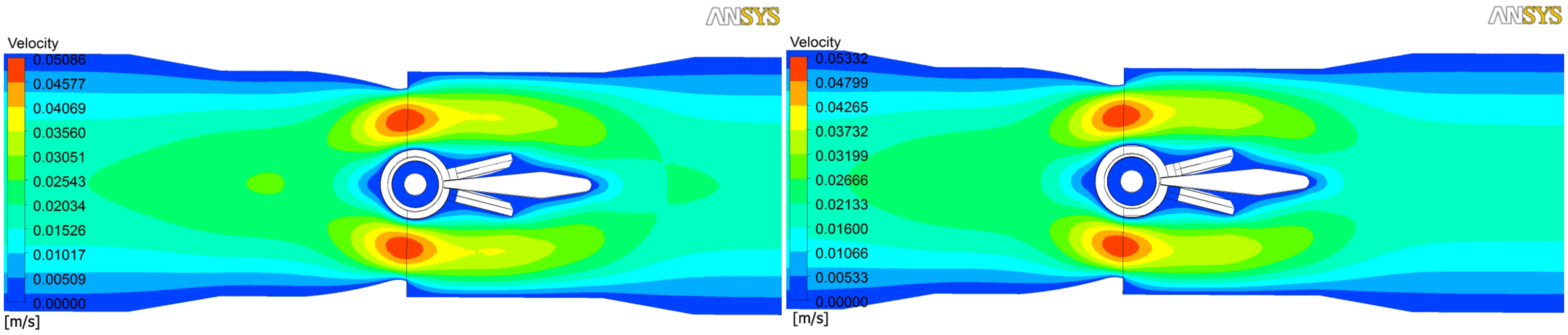
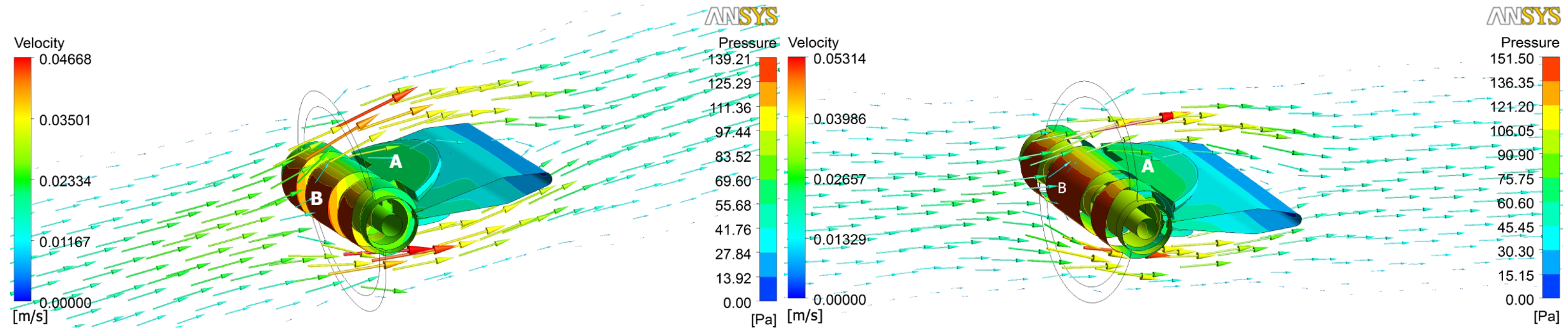
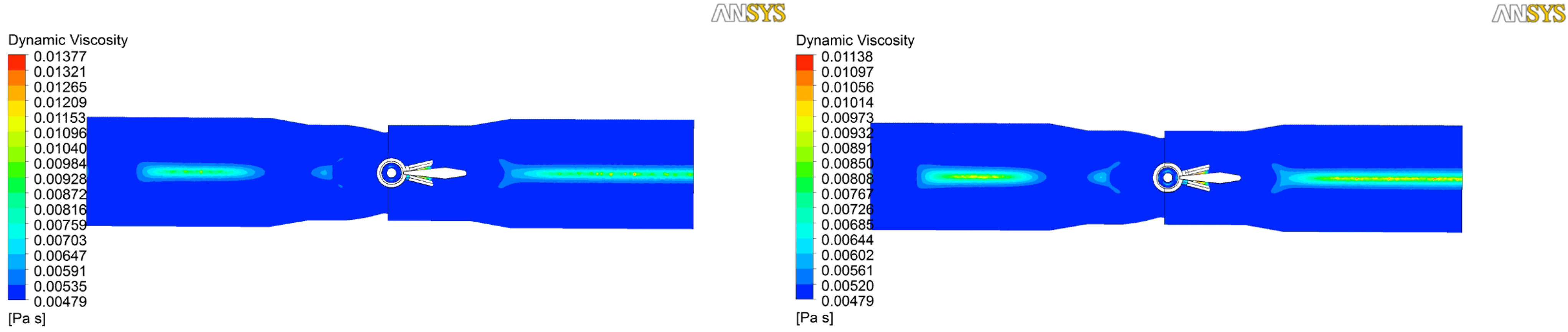
is the shear rate and n = 0.785 the non-Newtonian index [14]. At the inlet of the domain, a fully developed velocity profile of 1 cm/s was considered. At the outlet, a free flow outlet condition with null pressure was considered, while no-slip condition imposed at the solid surfaces. In order to avoid the influence of the boundary conditions, the computational domain extended for a length of 3 and 4 valve diameters downstream and upstream, respectively. The results are shown in Figure 4, Figure 5 and Figure 6. On the left hand side of each figure, simulations of the computer-designed micro-valve are shown while on the right hand side simulations of the fabricated one.
In Figure 4, streamlines of the velocity vector on the symmetry plane are shown. For the initial model (Figure 4a), as for the fabricated one (Figure 4b), the velocity field seems to be symmetric around the wings of the valve. Furthermore, it takes minimum values (blue color) on the solid surfaces, where the no-slip condition was considered, and maximum values (red color) at the narrowest part of the valve. For the initial CAD valve design (Figure 4a) the maximum velocity is 5.086 × 10⁻² m/s, while for the fabricated valve (Figure 4b) is quite higher, 5.332 × 10⁻² m/s. It is noteworthy, that despite the quite different geometric characteristics of the two valves, ranging from 0.28% to 26.7%, the maximum velocities that arise around the valve differ slightly. It is noted that, if the surface irregularities of the actual fabricated valve are taken into account, the maximum velocity is expected to increase.
Figure 4. Streamlines of the velocity on the symmetry plane. (a) the initial CAD valve design; (b) the multi-photon polymerization (MPP) fabricated one.
Micromachines 05 00505 g004
In Figure 5, the velocity vectors and the pressure field around the valves’ wings are shown. The velocity vectors around both valves show that no recirculation exists around the valve and the blood flows normally. As for the pressure, seems that it takes its highest values on the axis of the valve (point B in Figure 5a,b). For the initial CAD valve the maximum pressure is 139.2 Pa, while for the fabricated one the maximum pressure is 151.5 Pa. On the valve wings (point A in Figure 5a,b), the pressure is 55.68 Pa for the initial valve and 60.6 Pa for the fabricated one. Pressure difference, as for the velocity case, between the two valves is quite low (8.12%), while it is expected to increase if any stair-step effects of the fabricated valve are considered.
Figure 5. Velocity vectors and streamlines of the pressure on the wings of the valve. (a) the initial valve design; (b) the fabricated one.
Micromachines 05 00505 g005
Finally, in Figure 6, the distribution of the dynamic viscosity, μ, on the symmetry plane is shown. From the values of the dynamic viscosity and its distribution along the valve, it is obvious that the fluid behaves as non-Newtonian.
Figure 6. Streamlines of the dynamic viscosity on the symmetry plane of the valve. (a) the CAD valve design; (b) the fabricated one.
Micromachines 05 00505 g006

4. Discussion

The fabrication accuracy of the micro-valve depends mainly on the appropriate choice of the following parameters: (a) The laser beam power; (b) The hatching of the internal area at each slice the whole valve sliced; (c) The objective lens. The dimensions of the micro-valve fabricated in this work were such that the objective lens 20×, N.A. = 0.8 was chosen as a suitable one. As optimum laser beam power during the irradiation of the photosensitive hybrid material a value of 27 ± 1 mW was chosen. Several fabrication tests of the micro-valve were completed using lower and higher beam powers than the aforementioned one but without satisfactory results. More specifically, when the beam power was some mWs lower than 27 mW, the polymerization of the hybrid material was not complete, and the valve collapsed. Irradiation with some mWs higher had as result the appearance of distortion, mainly inside the valve, thus reducing the interface gaps. Another critical parameter influencing the accurate fabrication of the valve was the selection of hatching. This parameter refers to how dense the laser writes inside the area of each slice. The determination of the hatching value was achieved after many fabrication tests of the valve. Hatching values lower than 0.02 μm lead to time consuming fabrication process while higher values, more than 0.02 μm, resulted to insufficient polymerization of some areas inside the valve. It is noted that these three critical parameters for the successful fabrication of the micro-valve are not independent of each other. In Figure 2f, an SEM image of the micro-valve is depicted. The dimensional and geometrical characteristics of the built valve were comparable to the initial CAD design.
The results from the flow simulations are quite similar for the initial CAD valve design and the fabricated one for axial velocity of 1 cm/s and open valve condition. As can be seen in Figure 4, the flow field is symmetrical exhibiting flow acceleration in the narrowest part of both valves. The pressure profile of the fully opened valve obtains a maximum value on the central rotation axis of both valves as depicted in Figure 5. In both cases, no flow recirculation areas exist. The dynamic viscosity of the blood inside the flow domain varied slightly as can be seen in Figure 6, implying that the blood behaves as a non-Newtonian fluid. As can be seen in Figure 2, the micro-valves can be fabricated with high accuracy and without significant geometrical distortion, after the implementation of the appropriate compensation shrinkage factor. One disadvantage of the layer-by-layer fabrication technique is the stair-step effect around the curved areas. This effect was minimal in the fabricated structures but can introduce distortions to the fluid flow in such small micro-dimensions. The valves fabricated in the context of this work do not seem to have significant stair-step effects because the laser intensity was chosen so that the stair-step effects were comparable to the material resolution at the laser flux used.
It would be very interesting to investigate the mechanical properties of fabricated valve and compare it to those of a real vein. It is possible to tailor the mechanical properties of such structures by either changing the volume fraction of the used photopolymer [15], or by developing new polymers with tailored mechanical properties [16].

5. Conclusions

In this work, a complicated micro-valve has been fabricated employing the multi-photon polymerization technique. The design of the investigated micro-valve had dimensions and geometries similar to human veins. The fabricated valve had similar operational and geometrical characteristics when compared to the computer generated initial design. In order to examine the flow performance of both valves, computational fluid simulations were performed. For that purpose, the fabricated valve was transferred into a CAD model taking into account only its geometrical characteristics and not any surface stair-step effects, as a result of the fabrication process. The performed computational analysis demonstrated a good agreement of the velocity and the pressure profiles obtained for both the initial valve design and the fabricated one.

Acknowledgments

This work has been funded by the THALIS Program of the Hellenic Ministry of Education and within the context of MIS380278 research project. The authors are grateful to Mrs Aleka Manousaki for her technical assistance with SEM.

Author Contributions

S. Galanopoulos performed the fabrication experiments. N. Chatzidai performed the computational fluid dynamics analysis. V. Melissinaki and A. Selimis set-up the DLW system and helped with fabrication. C. Schizas designed the micro-valve. M. Farsari and D. Karalekas designed and supervised the project. All authors contributed to writing the manuscript.

Conflicts of Interest

The authors declare no conflict of interest.

References

  1. Malinauskas, M.; Farsari, M.; Piskarskas, A.; Juodkazis, S. Ultrafast laser nanostructuring of photopolymers: A decade of advances. Phys. Rep. 2013, 533, 1–31. [Google Scholar] [CrossRef]
  2. Xu, B.B.; Zhang, Y.L.; Xia, H.; Dong, W.F.; Ding, H.; Sun, H.B. Fabrication and multifunction integration of microfluidic chips by femtosecond laser direct writing. Lab Chip 2013, 13, 1677–1690. [Google Scholar] [CrossRef]
  3. Fischer, J.; Wegener, M. Three-dimensional optical laser lithography beyond the diffraction limit. Laser Photonics Rev. 2013, 7, 22–44. [Google Scholar] [CrossRef]
  4. Vasilantonakis, N.; Terzaki, K.; Sakellari, I.; Purlys, V.; Gray, D.; Soukoulis, C. M.; Vamvakaki, M.; Kafesaki, M.; Farsari, M. Three-Dimensional Metallic Photonic Crystals with Optical Bandgaps. Adv. Mater. 2012, 24, 1101–1105. [Google Scholar] [CrossRef]
  5. Olsen, M.H.; Hjorto, G.M.; Hansen, M.; Met, O.; Svane, I.M.; Larsen, N.B. In-chip fabrication of free-form 3D constructs for directed cell migration analysis. Lab Chip 2013, 13, 4800–4809. [Google Scholar] [CrossRef]
  6. Ovsianikov, A.; Mironov, V.; Stampfl, J.; Liska, R. Engineering 3D cell-culture matrices: Multiphoton processing technologies for biological and tissue engineering applications. Expert Rev. Med. Devices 2012, 9, 613–633. [Google Scholar] [CrossRef]
  7. Raimondi, M.T.; Eaton, S.M.; Lagana, M.; Aprile, V.; Nava, M.M.; Cerullo, G.; Osellame, R. Three-dimensional structural niches engineered via two-photon laser polymerization promote stem cell homing. Acta Biomater. 2013, 9, 4579–4584. [Google Scholar] [CrossRef]
  8. Terzaki, K.; Kalloudi, E.; Mossou, E.; Mitchell, E.P.; Forsyth, V.T.; Rosseeva, E.; Simon, P.; Vamvakaki, M.; Chatzinikolaidou, M.; Mitraki, A.; et al. Mineralized self-assembled peptides on 3D laser-made scaffolds: A new route toward ʻscaffold on scaffoldʼ hard tissue engineering. Biofabrication 2013, 5, 045002. [Google Scholar] [CrossRef]
  9. Groen, M.S.; Brouwer, D.M.; Wiegerink, R.J.; Lotters, J.C. Design Considerations for a Micromachined Proportional Control Valve. Micromachines 2012, 3, 396–412. [Google Scholar] [CrossRef]
  10. Schizas, C.; Melissinaki, V.; Gaidukeviciute, A.; Reinhardt, C.; Ohrt, C.; Dedoussis, V.; Chichkov, B.N.; Fotakis, C.; Farsari, M.; Karalekas, D. On the design and fabrication by two-photon polymerization of a readily assembled micro-valve. Int. J. Adv. Manuf. Technol. 2010, 48, 435–441. [Google Scholar] [CrossRef]
  11. Danilevicius, P.; Rekstyte, S.; Balciunas, E.; Kraniauskas, A.; Jarasiene, R.; Sirmenis, R.; Baltriukiene, D.; Bukelskiene, V.; Gadonas, R.; Malinauskas, M. Micro-structured polymer scaffolds fabricated by direct laser writing for tissue engineering. J. Biomed. Opt. 2012, 17, 081405-1. [Google Scholar] [CrossRef]
  12. Seidlits, S.K.; Schmidt, C.E.; Shear, J.B. High-resolution patterning of hydrogels in three dimensions using direct-write photofabrication for cell guidance. Adv. Funct. Mater. 2009, 19, 3543–3551. [Google Scholar] [CrossRef]
  13. Sakellari, I.; Kabouraki, E.; Gray, D.; Purlys, V.; Fotakis, C.; Pikulin, A.; Bityurin, N.; Vamvakaki, M.; Farsari, M. Diffusion-Assisted High Resolution Direct Femtosecond Laser Writing. ACS Nano 2012, 6, 2302–2311. [Google Scholar] [CrossRef]
  14. Qing, X.; Damodaran, M. Computational modelling of non-Newtonian effects on flow in channels with moving wall indentations. Int. J. Comput. Fluid Dyn. 2001, 15, 329–336. [Google Scholar] [CrossRef]
  15. Juodkazis, S.; Mizeikis, V.; Seet, K.K.; Misawa, H.; Wegst, U.G.K. Mechanical properties and tuning of three-dimensional polymeric photonic crystals. Appl. Phys. Lett. 2007, 91, 241904. [Google Scholar] [CrossRef]
  16. Skarmoutsou, A.; Lolas, G.; Charitidis, C.A.; Chatzinikolaidou, M.; Vamvakaki, M.; Farsari, M. Nanomechanical properties of hybrid coatings for bone tissue engineering. J. Mech. Behav. Biomed. Mater. 2013, 25, 48–62. [Google Scholar] [CrossRef]

