1. Introduction
Worldwide, accurate measurement and control of small and extremely small mass flow rates is becoming more and more important, driven by numerous economically important applications in, for instance, semiconductor industry, analytical instrumentation, food, medical, pharmacy, energy, and micro reaction systems. Necessary components for these integrated microfluidic handling systems are for example proportional control valves, thermal flow sensors, Coriolis flow sensors, pumps, pressure sensors and temperature sensors. The individual components may exist, but they have never been designed from the system and industrial end-user point of view. In this paper, we propose to realise an integrated flow measurement system, composed of building blocks that are designed to fit within the system.
In [
1,
2] we presented a surface channel technology that can be used to realize both thermal [
3] and Coriolis [
4] flow sensors.
Thermal flow sensors are capable of measuring liquid flow down to a few nL/min by accurate measurement of very small flow-induced temperature changes [
3,
5]. However, their upper flow range is limited due to the transition from the calorimetric to the anemometric heat transfer regime. On the other hand, Coriolis flow sensors are capable of measuring large flow rates, but their resolution is limited due to the extremely small Coriolis forces. In [
4] we presented a micro Coriolis mass flow sensor with a very thin (1 μm) tube wall made of silicon nitride, resulting in a significant improvement in resolution compared to earlier devices [
6,
7]. This has opened the possibility to combine a thermal and a Coriolis flow sensor on a single chip [
8] with partially overlapping flow ranges in order to obtain a combined dynamic flow range of more than five decades.
2. Experimental Section
2.1. System Structure and Considerations
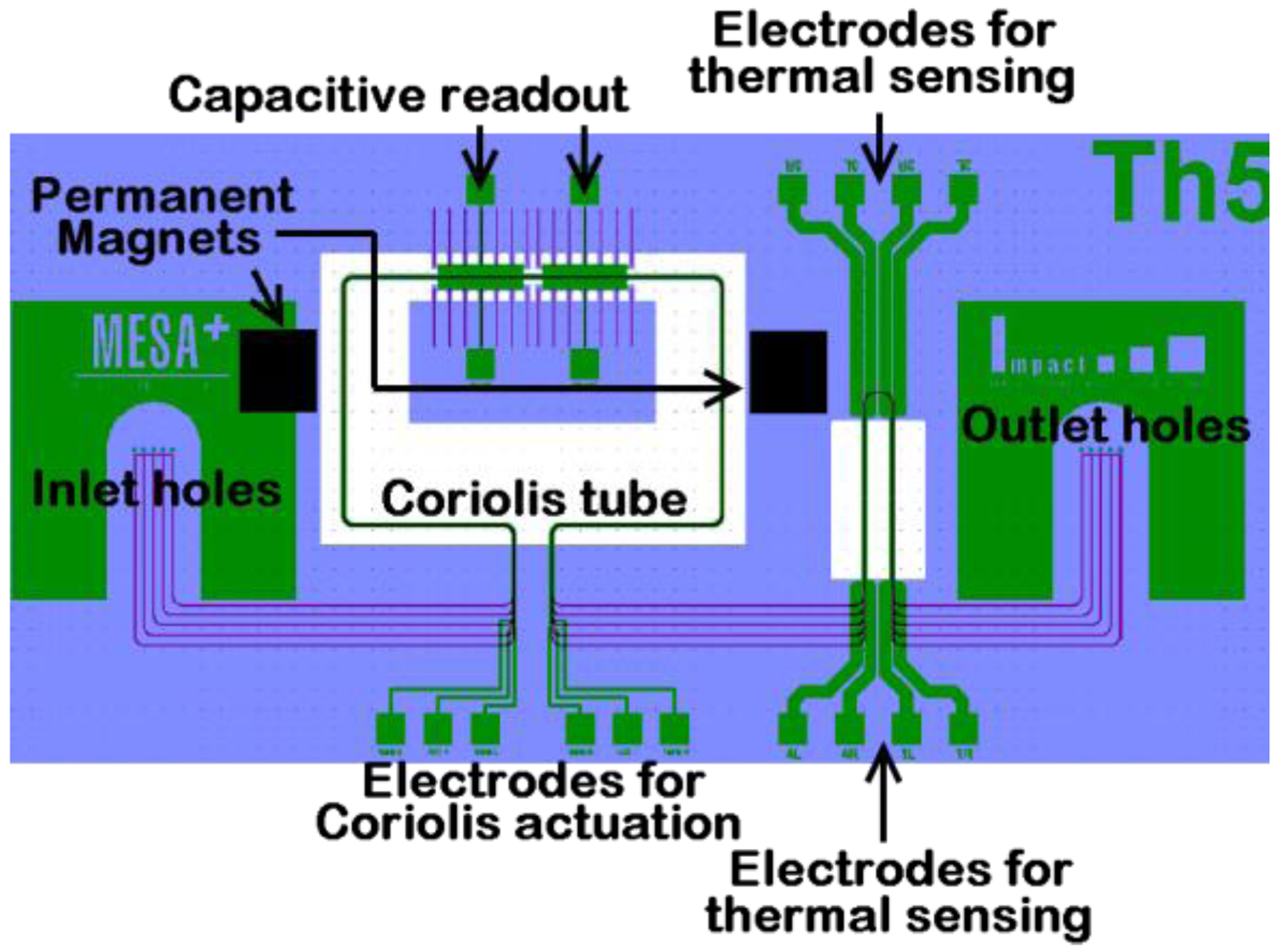
The single chip flow sensing system, as shown in
Figure 1, comprises a fluidic inlet, a Coriolis mass flow sensor, a thermal mass flow sensor, and a fluidic outlet. Fluid flow enters the system through the inlet holes, first goes through the Coriolis flow sensor, then through the thermal flow sensor, and leaves the system through the outlet holes.
Figure 1.
Structure of integrated thermal and microCoriolis flow sensing system.
Figure 1.
Structure of integrated thermal and microCoriolis flow sensing system.
The thermal flow sensor is sensitive to fluid properties like density and heat capacity, but can be used down to very small flows. The Coriolis sensor measures both mass flow and density, independent of other fluid properties, and is capable of measuring relatively large flows. The surface channel technology provides a unique opportunity to design a single chip flow measurement system with partially overlapping flow ranges. Since they are connected in series, both sensors experience the same liquid flow. Thus, integration with a Coriolis flow sensor provides means to calibrate the thermal sensor by using the overlap in flow range, even when it is already built-in in the application of the end-user, which cannot be obtained by using two separate flow sensors. This is especially of interest for application in e.g., HPLC (high-pressure liquid chromatography) equipment.
2.2. Thermal Flow Sensor
The thermal flow sensor, as shown in
Figure 2(a), consists of a silicon nitride microchannel that is freely-suspended over an etched cavity in the silicon substrate.
Figure 2.
(a) Thermal flow sensor with (b) Wheatstone bridge configuration.
Figure 2.
(a) Thermal flow sensor with (b) Wheatstone bridge configuration.
The channel crosses the cavity two times in order to eliminate external temperature gradients. Two resistors, that fulfill both the heating and sensing function, are positioned on each channel segment.
The resistors are connected in a Wheatstone bridge configuration, as shown in
Figure 2(b). A flow through the channel results in a corresponding output voltage of the Wheatstone bridge.
2.3. Coriolis Flow Sensor
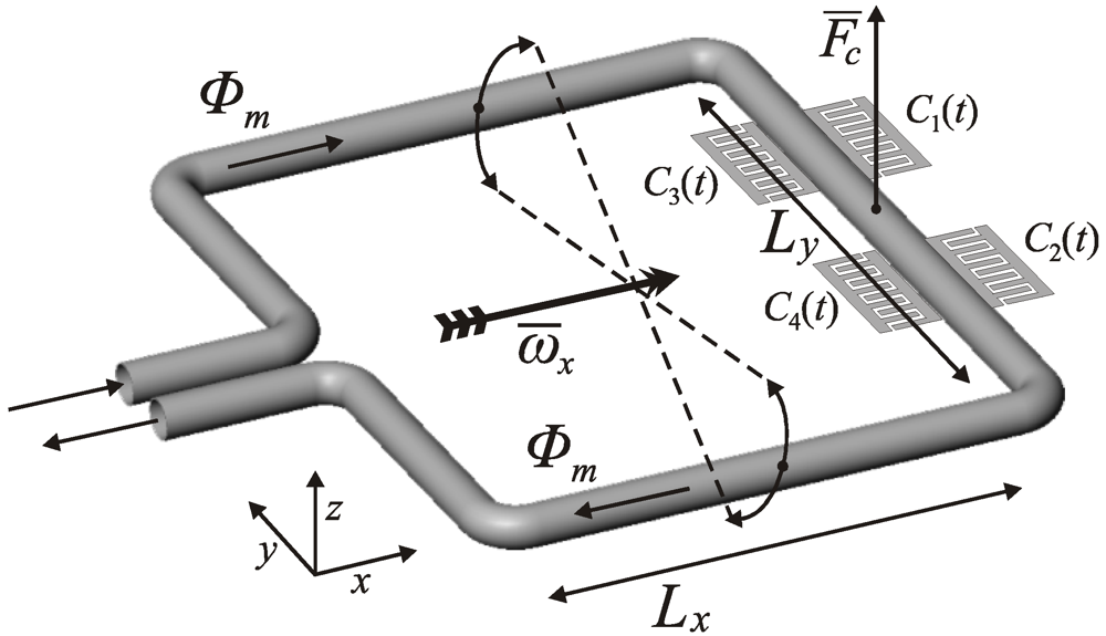
The Coriolis type flow sensor consists of a vibrating tube. Fluid flow inside the vibrating tube results in Coriolis forces that can be detected.
Figure 3 shows a schematic drawing of a Coriolis sensor based on a rectangular tube shape [
4]. The tube is actuated in a torsional mode indicated by
ωam, using the Lorentz force on an electrical ac-current
iact flowing through a metal track on top of the tube and a static external magnetic field
B imposed by two permanent magnets. A mass flow
Φm inside the tube results in a Coriolis force
Fc. The Coriolis force is capacitively detected by its induced out of plane vibration mode with an amplitude proportional to the mass flow.
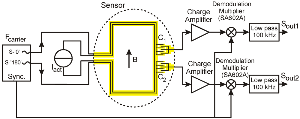
Figure 4 shows a schematic diagram of the complete sensor system with actuation and readout electronics [
4]. The comb-shaped capacitors used for readout are indicated by
C1 and
C2. The combs that are attached to the moving sensor tube are connected to a signal source with frequency
Fcarrier equal to 1.4 MHz. The fixed combs are connected to charge amplifiers and the resulting amplitude modulated signals are demodulated by multiplication with an in-phase reference signal. Low pass filters with relatively high cut-off frequency of 100 kHz are used to prevent phase shift at frequencies below 3 kHz,
i.e., the vibration frequency of the tube.
Figure 3.
Coriolis flow sensor.
Figure 3.
Coriolis flow sensor.
Figure 4.
Schematic diagram of the actuation and readout electronics.
Figure 4.
Schematic diagram of the actuation and readout electronics.
The measured mass flow can be extracted from the phase difference between the two output signals Sout1 and Sout2.
2.4. Fabrication Technology
Both flow sensors consist of a silicon nitride microchannel that is freely-suspended over an etched cavity in the silicon substrate, for either thermal insulation (thermal flow sensor) or to allow the tube to vibrate (Coriolis flow sensor). Here we give a brief summary of the fabrication process, a more detailed description can be found in [
4].
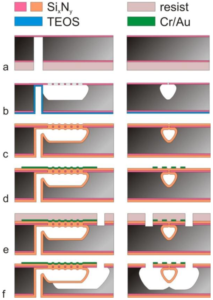
Starting with a highly doped <100> p++ wafer, a 500 nm thick low stress LPCVD silicon-rich silicon nitride (Si
xN
y) layer is deposited. Then the fluidic inlet/outlet holes are etched from the backside of the wafer using the Si
xN
y layer at the top side as etch stop (
Figure 5(a)). Next, a 1 µm thick TEOS (tetraethyl orthosilicate) oxide layer is deposited and removed from the front side of the wafer. Then a 50 nm layer of chromium is sputtered on the front side of the substrate. This chromium layer is patterned using a mask containing arrays of 5 × 2 µm holes, spaced 3 µm apart. This pattern forms the centerline of the final channel. The pattern is then transferred into the nitride layer by reactive ion etching and subsequently the channels are etched in the silicon using isotropic plasma etching (
Figure 5(b)). The TEOS layer and chromium mask are then removed and another Si
xN
y layer is grown with a thickness of 1.8 µm to form the channel walls and seals the etch holes in the first nitride layer (
Figure 5(c)). A 10/200 nm layer of chromium and gold is sputtered (chromium serving as the adhesion layer for gold) and patterned to create the metal electrodes for actuation and readout (
Figure 5(d)).
Next, the release windows are opened by reactive ion etching of the Si
xN
y layer (
Figure 5(e)) and the structure is released by isotropic silicon plasma etching (
Figure 5(f)).
Figure 5.
Outline of the fabrication process. Left column: cross-section along the length of the tube. Right column: cross-section perpendicular to the sensor tube.
Figure 5.
Outline of the fabrication process. Left column: cross-section along the length of the tube. Right column: cross-section perpendicular to the sensor tube.
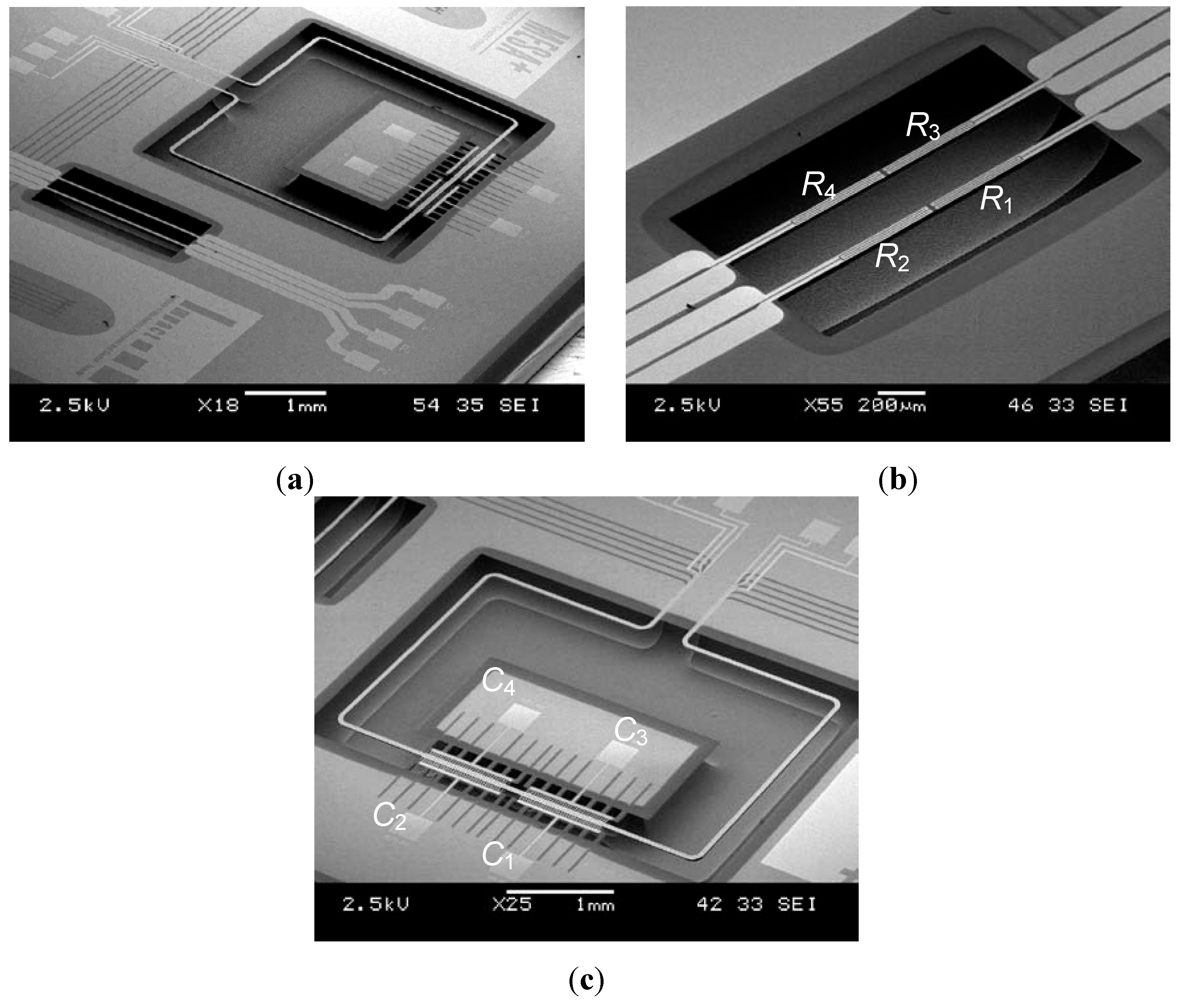
The realized single chip flow sensing system is shown in
Figure 6(a), with the thermal and Coriolis flow sensor shown in more detail in
Figure 6(b,c), respectively. The tube diameter is approximately 40 μm. The entire chip measures 7.5 mm × 15 mm.
Figure 6.
SEM photographs of the combinedsingle chip thermal/Coriolis flow sensing system: (a) Overview of the chip, (b) thermal flow sensorand (c) Coriolis flow sensor.
Figure 6.
SEM photographs of the combinedsingle chip thermal/Coriolis flow sensing system: (a) Overview of the chip, (b) thermal flow sensorand (c) Coriolis flow sensor.
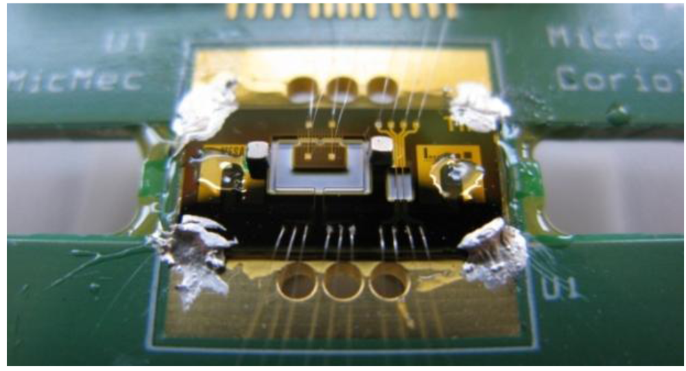
A picture of the single chip flow sensing system mounted on a printed circuit board is shown in
Figure 7.
Figure 7.
Single chip flow sensing system, mounted on a printed circuit board.
Figure 7.
Single chip flow sensing system, mounted on a printed circuit board.
2.5. Measurement Set-Up
A syringe pump system, as shown in
Figure 8, was used to generate water flows in the range of 100 nL/h up to 18 mL/h through the chip. During the measurements the output signals of both the thermal and the Coriolis flow sensor were recorded simultaneously, together with the control signal of the syringe pump system, which is used as a reference for the mass flow rate. Particle filters were installed at the inlet and outlet of the chip to prevent clogging.
Figure 8.
Measurement set-up. Water flow is provided by a syringe pump and checked with a balance.
Figure 8.
Measurement set-up. Water flow is provided by a syringe pump and checked with a balance.
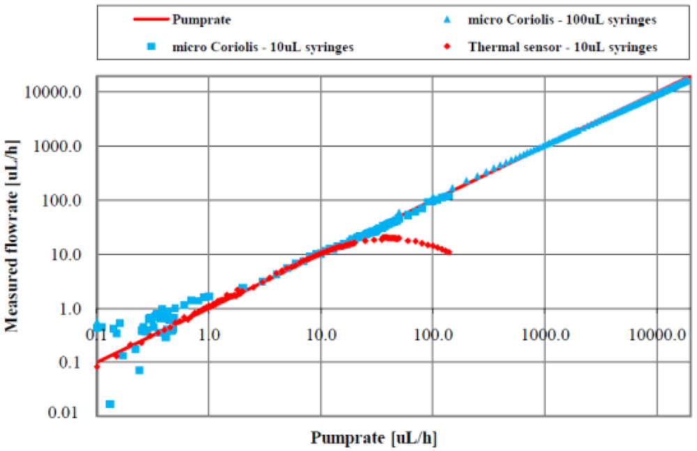
3. Measurement Results and Discussion
In
Figure 9, the volume flow as measured by both the thermal and the Coriolis mass flow sensor are displayed
versus the flow rate as set by the syringe pump.
Figure 9.
Measurement results demonstrating a dynamic range of more than five decades.
Figure 9.
Measurement results demonstrating a dynamic range of more than five decades.
The thermal flow sensor provides an almost linear output signal from the lowest flow of 0.1 µL/h through approximately 5 µL/h. Then, the curve flattens and reaches its top at approximately 40 µL/h, after which the output signal decreases with further increasing flow. The limitation of the upper flow range is due to the transition from the calorimetric to the anemometric heat transfer regime [
9].
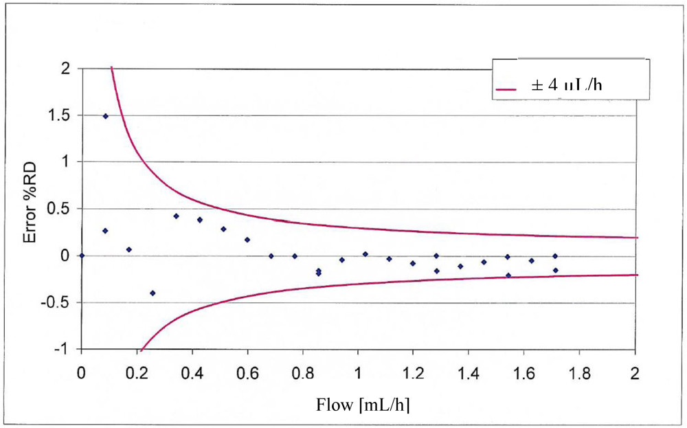
Figure 10.
Measured accuracy of the Coriolis flow sensor.
Figure 10.
Measured accuracy of the Coriolis flow sensor.
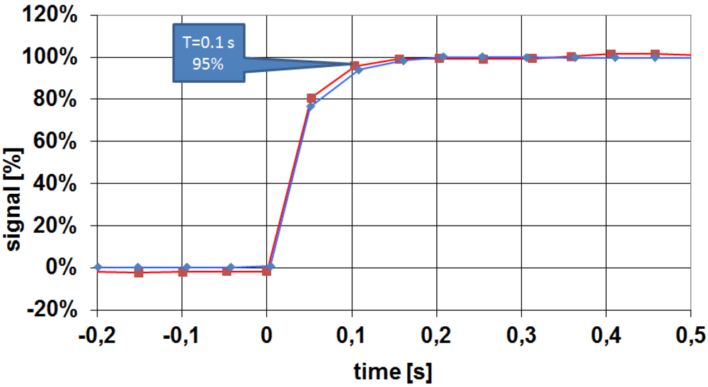
Figure 11.
Measured response time of the Coriolis flow sensor; the same sensor was measured twice; 100% equals 1,000 µL/h.
Figure 11.
Measured response time of the Coriolis flow sensor; the same sensor was measured twice; 100% equals 1,000 µL/h.
The low flow limitation of 0.1 µL/h is caused by the size of the syringes used (10 µL). Smaller syringes (1 µL) have been ordered to measure even lower flows. The absolute minimum detectable flow rate will eventually be determined by the signal to noise ratio of the thermal flow sensor and the thermal stability of the measurement set-up. Currently, the signal to noise ratio (SNR) of the thermal flow sensor with the Wheatstone bridge configuration is of the order of 0.03 µL/h, further improvement is needed towards an SNR of less than 0.01 µL/h. The measurable flow range of the thermal flow sensor was found to be from 0.1 up to 40 µL/h, with an accuracy of <±0.1 µL/h.
The Coriolis flow sensor provides a linear output signal from the lowest measurable flow of 10 µL/h up to the highest measured flow of 18 mL/h, with an accuracy of better than ±4 µL/h, as shown in
Figure 10. The response time of the Coriolis flow sensor was found to be of the order of 0.2 s, as can be seen in
Figure 11.
The low flow limitation of 10 µL/h is caused by the limited zero-stability of the Coriolis flow sensor due to the extremely small Coriolis forces [
4].
The high flow limitation is caused by leakage in the system: the flow of 18 mL/h required a pressure of 18 bar at the inlets, and the fittings used in the measurement set-up were not capable of withstanding this pressure. The total calibration system will be improved for this purpose. It should be noted that a pressure drop of 18 bar over the sensor is not so much of a problem in HPLC applications, since the total available pressure in this type of equipment may exceed 1,000 bar. In principle, the surface channel technology is capable of withstanding such high pressures, however, this has still to be demonstrated.
The combination of the thermal and the Coriolis flow sensor into a single chip flow sensing system results in a measurable flow range of 100 nL/h up to 18 mL/h, a dynamic flow range of more than five decades. Transition point is a flow of 10 µL/h: in case the output signal of the flow sensing system indicates a flow equal to or less than 10 µL/h, the signal of the thermal flow sensor should be used; subsequently, the signal of the Coriolis flow sensor should be used in case the output signal of the flow sensing system indicates a flow higher than 10 µL/h. To obtain a valid comparison between both signals, the fluid type should not vary during the measurement, otherwise the Coriolis flow sensor will experience a different fluid than the thermal flow sensor, and thus the output signals will indicate different flows.
Please note that particle filters should be used at the inlet and outlet of the chip to prevent clogging of the small sensor tube, which has an internal diameter of only ca. 30 µm.
4. Conclusions
We have designed and realized a micromachined single chip flow sensing system covering an unprecedented ultra-wide dynamic flow range of more than five decades, from 100 nL/h up to 18 mL/h. The system comprises both a thermal and a micro Coriolis flow sensor with partially overlapping flow ranges, enabling in-use calibration of the thermal flow sensor by using the signal of the Coriolis flow sensor.
The thermal flow sensor consists of a silicon nitride microchannel with resistors positioned on it, which function both as heater and sensor, and are connected in a Wheatstone bridge configuration. Its measurable flow range goes from 0.1 up to 40 µL/h with an accuracy of ±0.1 µL/h.
The Coriolis flow sensor consists of a vibrating tube. Fluid flow inside the vibrating tube results in Coriolis forces that are capacitively detected. Its measurable flow range was found to be 10 µL/h up to 18 mL/h with an accuracy of ±4 µL/h and a response time of 0.2 s.
The flow sensing system was realized using thin-walled silicon nitride channels.
