1. Introductions
Multiple coupled microcavities have been widely utilized for optical communication systems [
1,
2,
3,
4,
5,
6,
7,
8,
9]. For wavelength division multiplexing (WDM) techniques, optimal filter design is mandatory and flat responses are ultimately required [
3]. Higher order coupled microcavities have been proposed as promising candidates for optical filtering. The dispersion analysis of large chain of microcavities has been recently introduced [
5]. The application of multiple coupled microcavities can be extended to optical signal processing and routing. Systematic and rigorous design procedures are essential to obtain the required filter response especially with large number of microcavities.
The design of coupled resonators is usually done through the coupling parameters [
10,
11,
12,
13,
14,
15,
16,
17,
18,
19]. These parameters have a direct effect on the achievable transfer function of the filter. Once the coupling coefficient for each stage is determined, the geometrical specifications for each resonator are adjusted [
11]. The design theory of coupled microcavities has been originally developed for microwave filters [
20,
21,
22]. In the last decade, this work was extended to the design of optical filters [
11] using Bragg gratings and ring resonators. In [
11,
12], the design procedure utilizes a transmission line equivalent network. Distributed capacitances and inductances are utilized to build a filter prototype which is mapped to the corresponding equivalent resonator design [
21]. The method is used successfully for the design of Chebyshev-based filters [
11]. Other filter types can be readily designed using different cascading configurations [
12]. This design approach is limited to narrow band responses [
21]. It is also based on add drop filters, where the output is only at the drop port of the coupled structure. Other approaches are developed for the optimal placement of zeros and poles of the filter transfer function [
23] and [
24]. These approaches are intended for the design of parallel and series coupled ring resonators [
24]. They utilize resonators of equal coupling parameters to overcome the complexity of the design. Using these approaches, tapering of the coupling parameters is done intuitively [
24]. This intuitive tuning is successful for a small set of cascaded series or parallel ring resonators. For higher order filters, optimal responses are not guaranteed.
We discuss in this review two simple structured optimization methods for the design optimization of coupled microcavities. Though these techniques are simple, they can design filters with tens of coupled microcavities in few seconds. These techniques are based on adopting simplified transfer functions that transform the nonlinear optimization problem of highly coupled parameters to a linear optimization problem with a global solution. In the first technique [
25], the microcavity coupling parameters are assumed to vary around known mean values. A perturbation theory is developed to propose a design optimization problem in the perturbation parameters. By dumping the higher order perturbation terms, we ignore the effect of multiple reflections among the rings introduced by the small adjustment of the coupling coefficients. This is a first order accurate approach as it takes into account only multiple reflections introduced by the zero order terms. The design problem is then formulated as a linear least square design problem. This linear least square problem has a unique solution that can be obtained in few seconds for tens of design parameters [
26]. This can be contrasted with other approaches that converge to a local solution [
14,
15,
16].
Another efficient approach for filter design using a large number of cascaded microcavities is based on linear phase filter (LPF) approximation [
27]. An approximate objective function is exploited to solve the design as a linear program (LP) problem. This allows for fast and efficient solution of large scale problems. In addition, no initial design is required. The LP solver can find a feasible starting point by solving an initial feasibility problem. The computational time is less than one second for structures that contains up to 150 coupled microcavities.
This paper is organized as follows. The theory of cascaded series rings is summarized in
Section 2. The perturbation approach is addressed in
Section 3.
Section 4 is dedicated for the linear phase filter approach. The conclusions are given in
Section 5.
2. Theory of Coupled Microcavities
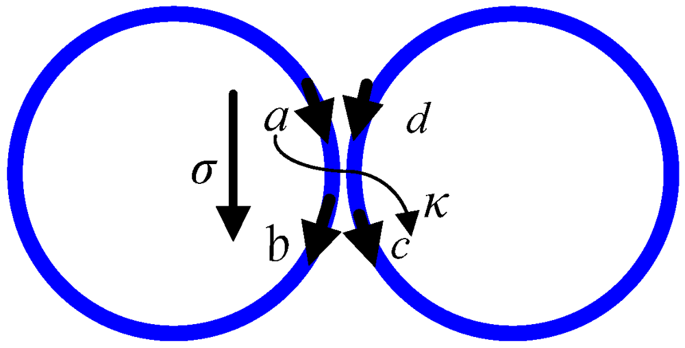
Complex ring configurations contain multiple ring to ring coupling stages. Each stage incorporates a directional coupler approximation. A single stage coupling is shown in
Figure 1, where
a,
b,
c, and
d are the field values at the interfaces. The quantities
σ and
κ represent the through and cross-port field coupling parameters, respectively. The relationship between the fields can be summarized using the scattering matrix [
28]:
![Micromachines 03 00204 i001]()
(1)
Figure 1.
Coupled ring resonators.
Figure 1.
Coupled ring resonators.
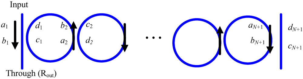
For the series-connected ring resonators shown in
Figure 2, the
a and
b fields at the
ith stage are related to the fields at the next stage through the relationship:
![Micromachines 03 00204 i002]()
(2)
![Micromachines 03 00204 i003]()
(3)
Here, γ = θ − jα is the complex propagation factor inside curved structures. θ is the phase factor due to the propagation inside the ring and is given by:
![Micromachines 03 00204 i004]()
(4)
where f is the light frequency, neff is the real part effective waveguide index, and Lc is the cavity length of the resonator. The parameter α is the field attenuation coefficient.
Figure 2.
The structure of cascaded coupled ring resonators.
Figure 2.
The structure of cascaded coupled ring resonators.
For N resonator stages, the total transfer matrix is given by:
![Micromachines 03 00204 i005]()
(5)
The coupling parameters between the Nth ring and the output waveguide are σN+1 and κN+1. Utilizing bN+1 = −σN+1aN+1, the transfer function for the through port (reflectivity) Rout= b1/a1 is given by:
![Micromachines 03 00204 i006]()
(6)
Utilizing cN+1 = jκN+1aN+1, the transfer function for the drop port (transmissivity) defined as cN+1/a1 is given by:
![Micromachines 03 00204 i007]()
(7)
The calculated transfer functions in Equations (6) and (7) are utilized for analyzing coupled resonators of known ring coupling parameters at every stage σi, κi, ∀i.
It is a common procedure to transform a linear system to a suitable frequency domain representation. This representation can be further utilized to simplify both the analysis and synthesis of the cascaded system [
24]. Similar to the procedure of discrete digital filters design, we utilize
Z domain representation of the optical filter response [
24]. This is accomplished by utilizing
z−1 = e
−jθ, where
z−1 includes only the phase factor. All the transfer matrices are thus
z-dependent and both
Rout and
Tout are transformed to the
Z domain:
![Micromachines 03 00204 i008]()
(8)
The response of the coupled ring resonators follows the standard form of a linear discrete system (see Equation (8)). The calculated transfer function coefficients
pn and
qm controls the achievable response in terms of pass band and stop band quality and the extinction ratio as well. These coefficients are dependent on the ring coupling parameters (
σi,
κi) and cavity loss parameter defined as
![Micromachines 03 00204 i009]()
for all rings. Control of the waveguide to ring and ring to ring scattering parameters allows for a high degree of freedom to achieve different targeted filter responses. The Optical filter realization can be realized from either the through or the drop ports.
3. Efficient Perturbation Technique
The filter coefficients in Equation (8) are of nonlinear dependence on the coupling parameters. Those nonlinear terms are the contribution of multiple coupling among the cascaded resonators. For large values of coupled parameters, we cannot neglect multiple coupling. Utilizing the perturbation theory, a simple formulation to reduce the complexity of the filter transfer function is developed. For global optimization of cascaded series rings filters, robust optimization techniques can be incorporated to provide optimal filter designs. For the proposed approach, the target design has a set of mean coupling parameters. Then we formulate a modified design optimization problem to estimate the required perturbation of the coupling parameters around the mean to achieve the desired filter response. The overall coupling coefficients are thus calculated. This approach does not neglect the multiple coupling effects and take into consideration the unavoidable resonator losses.
For N cascaded coupled resonators, the coupling coefficient at each stage is perturbed round a mean value as:
![Micromachines 03 00204 i010]()
(9)
Substituting from Equation (9) in Equation (8), the polynomials
A and
B are of
N + 1 order dependence on the individual perturbations
δσi, ∀
i. Assuming small perturbations
δσ = [
δσ1,
δσ2, …,
δσN+1]
T, higher order terms can be neglected. By ignoring the higher order perturbation terms, we neglect the effect of multiple reflections among the rings introduced by the small adjustment of the parameters
σ. This is a first order accurate approach as it takes into account only multiple reflections introduced by the zero order terms
![Micromachines 03 00204 i011]()
. A linear approximation of the polynomials
B(
z) and
A(
z) dependence on the perturbed through port coupling
δσ can thus be formulated. In this case we have:
![Micromachines 03 00204 i012]()
(10)
In Equation (10),
ci and
di are the zero order terms in
δσ that can be calculated by substituting with
![Micromachines 03 00204 i011]()
in Equation (8). The coefficients of the first order terms in
δσ are represented by
hi and
gi, both are polynomials in
![Micromachines 03 00204 i011]()
.
In order to achieve a filter response with specific z-dependence, we match the ring filter coefficients (p, q) to the targeted filter coefficients (b, a). The following system of linear equations is thus constructed:
![Micromachines 03 00204 i013]()
(11)
In Equation (11), b and a are the vectors of the numerator and denominator polynomials of the target filter transfer function (8). The solution of the linear system of equation in Equation (11) produces the optimal δσ that satisfies the target filter transfer function.
The system of linear Equation (11) is overdetermined. However, a least squares solution leads to the optimal perturbation parameters. The design problem can thus be cast as a constrained optimization problem with a quadratic objective function over linear constraints:
![Micromachines 03 00204 i014]()
(12)
In Equation (12), the first constraint is placed to ensure the total through coupling parameter less than unity. The second constraint imposes a trust region for the perturbation model. The parameter
ζ is the maximum allowable perturbation in the coupling parameters. This problem is convex and leads to a unique optimal design [
26].
For lossy structures, the total loss of the ring modifies the optimization problem constraints. This can be taken into consideration by a direct modification of the system coefficients in Equations (10) and (11). The same system of equations is solved to get the perturbation in the coupling coefficients in the presence of the losses.
Our formulation can be contrasted with other conventional nonlinear least square problems. These approaches have complex dependence on parameters, computationally expensive and their solution is not globally optimal.
The perturbation technique is verified through the design of fifth order and tenth order optical filters using series connected ring resonators. We carry out optimization for both lossless and lossy structures. The optimization algorithm achieves the required response efficiently within the trusted perturbation region. Our algorithm is also applied to a set of lossy structures to predict the change in the achievable design with a loss increase.
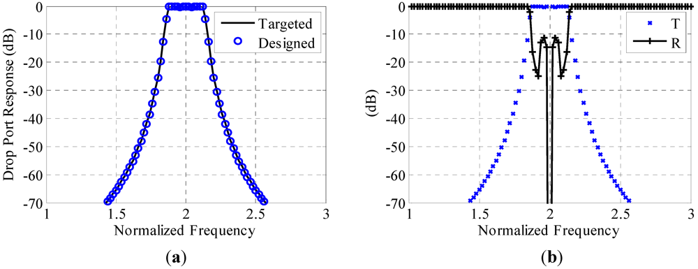
3.1. Fifth Order Ring Resonator Filter
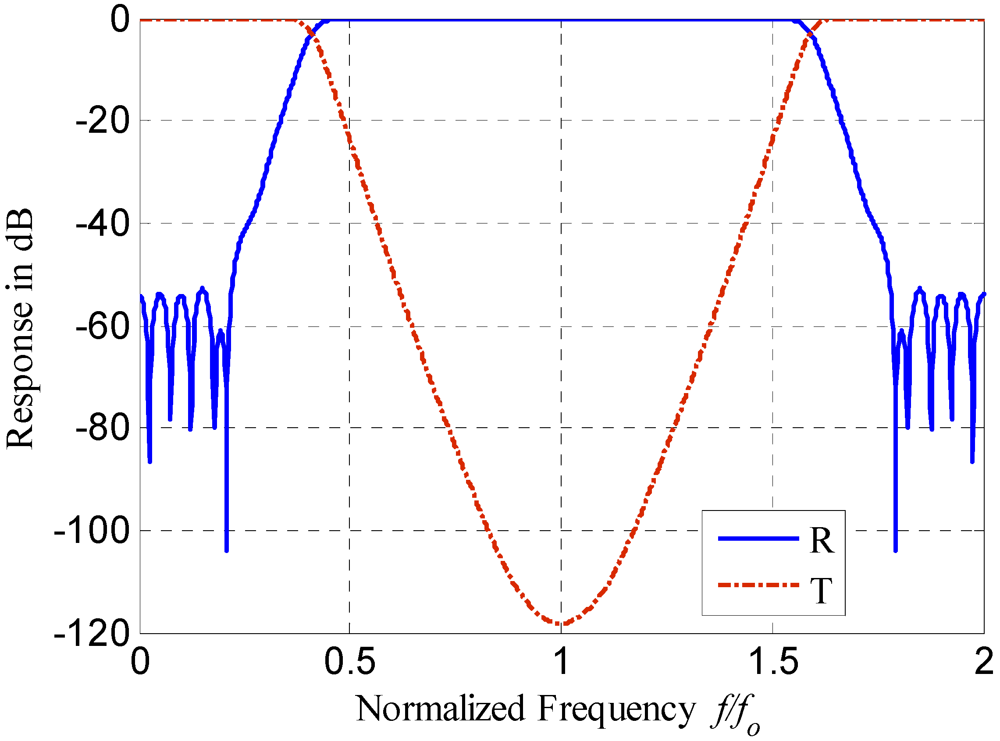
For an ideal target response, we have applied our approach to the design of the fifth order drop filter [
8]. The filter response is a typical IIR filter which can be controlled to have different pass band, stop band, and stop band reduction. For this filter, the pass band occupies approximately one seventh of the free spectral range. The pass band ripples are less than 0.4 dB and the stop band rejection is more than 40 dB. In order to achieve these specifications, a target
z domain transfer function is constructed. For the realization of this transfer function using ring resonators, we assume a known waveguide to ring through coupling coefficient of 0.7416 [
8]. The ring to ring mean through coupling is assumed to be 0.9. This value is an acceptable approximation for a required filter response from the drop port. It assures the validity of our algorithm for a high value of the mean through coupling coefficient.
Figure 3.
(
a) The achieved fifth order filter response as compared to a targeted fifth order filter proposed in [
8]. (
b) The responses at the through port (R) and the drop port (T) for the five cascaded ring resonators.
Figure 3.
(
a) The achieved fifth order filter response as compared to a targeted fifth order filter proposed in [
8]. (
b) The responses at the through port (R) and the drop port (T) for the five cascaded ring resonators.
Our algorithm is applied to extract the vector of perturbation in the through coupling parameters (
δσ). The convexity of the optimization problem yields a unique solution regardless of the initial starting point. The application of our technique results in a perfect match with the target filter as shown in
Figure 3. The exact transfer function is utilized to calculate the responses at both the through and drop ports (see
Figure 3(b)). The optimal coupling perturbations
δσ = [0.0602 0.0753 0.0753 0.0602]
T result in a symmetric structure. The ring resonator drop port transfer function is as follows:
![Micromachines 03 00204 i015]()
(14)
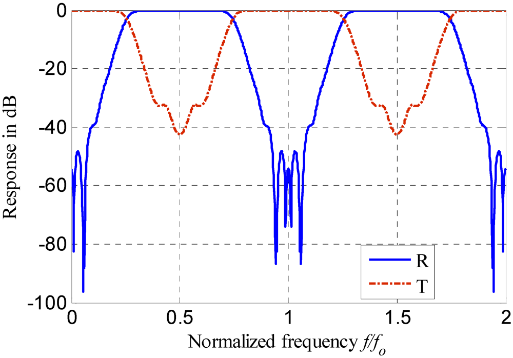
3.2. Tenth Order Ring Resonator Filter
Our technique is also utilized to design a number of ten series connected rings. For this example, the targeted filter has small pass band ripples with an increased normalized bandwidth and improved steep filter pass band to stop band transition. The targeted filter design is proposed using matlab digital filter design functions [
29]. Our technique is then utilized to determine the best rings coupling parameters to achieve the target design.
The target filter is a Chebyshev type I filter with a bandwidth of one third of the free spectral range and minimal pass band ripples. The (cheby1) matlab function [
29] is utilized with ripple parameters of 0.001 and normalized band width of 0.33. The target vector of the denominator polynomial coefficients is a = [1.0000 −5.2448 13.8635 −23.6303 28.3988 −24.9452 16.1369 −7.5663 2.4561 −0.4980 0.0479]
T.
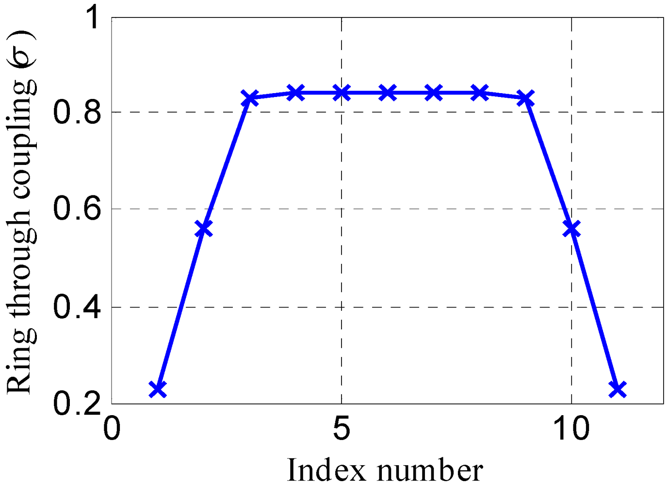
Figure 4.
The coupling coefficients for the optimized tenth order optical filter utilizing the perturbation approach.
Figure 4.
The coupling coefficients for the optimized tenth order optical filter utilizing the perturbation approach.
Figure 5.
(a) The achieved tenth order filter response as compared to the target response. (b) The responses at the through port (R) and the drop port (T) for the ten cascaded ring resonators.
Figure 5.
(a) The achieved tenth order filter response as compared to the target response. (b) The responses at the through port (R) and the drop port (T) for the ten cascaded ring resonators.
For this problem, the number of optimization parameters is 11 representing the through coupling coefficient
σi for all the stages. Equation (12) is utilized with average couplings
![Micromachines 03 00204 i016]()
= [0.25 0.5 0.75 0.75 0.75 0.75 0.75 0.75 0.75 0.5 0.25]
T. The perturbation trust region size
ζ is set to 0.1. The optimal coupling coefficients are shown in
Figure 4. The achieved response and the target response are shown in
Figure 5(a). Good match is achieved between the two responses. The response of the ring resonators at the through port (reflectivity) compared to the response at the drop port (transmissivity) is shown in
Figure 5(b).
3.3. Fifth Order Lossy Filter
To illustrate the accuracy and correctness of the perturbation approach, we also compare our results to that is in [
11]. We design the target filter in [
11] utilizing both ideal and lossy coupled ring resonators. In [
11], a fifth order filter is utilized to achieve a highly selective filter with a bandwidth of 20% of the free spectral range and a maximum passband flatness. Utilizing the method in [
11], the achievable design has ring through couplings
σ = [0.4186 0.821 0.909 0.909 0.821 0.4186]
T. The target vector of the polynomial coefficients in Equation (8) is
a = [1.0 −3.0083 4.0132 −2.8776 1.0944 −0.1753].
We utilize our approach for the design of the same target filter. The average couplings
![Micromachines 03 00204 i016]()
= [0.45 0.85 0.85 0.85 0.85 0.45]
T are utilized. The perturbation trust region size
ζ is set to 0.2. The optimal set of coupling are
σ = [0.421 0.808 0.917 0.917 0.808 0.421]
T utilizing lossless coupled ring resonators. The designed polynomial coefficients are
a = [1 −3.0053 4.00 −2.8652 1.0939 −0.1776].
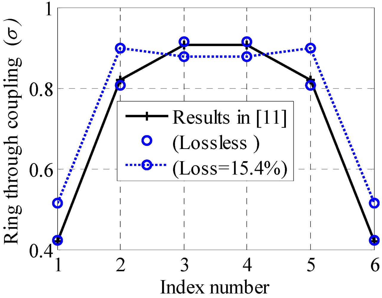
Figure 6 shows the filter response utilizing our approach. It has a good agreement with the target filter. The ability of our perturbation algorithm to predict the optimal design is best illustrated in
Figure 7. The optimal coupling coefficients for the lossless case have a very good match with the results in [
11].
Figure 6.
The achieved fifth order filter response utilizing the perturbation approach for both lossless and lossy structures as compared to the target filter.
Figure 6.
The achieved fifth order filter response utilizing the perturbation approach for both lossless and lossy structures as compared to the target filter.
To further illustrate the universality of our approach, we design the same ideal target filter utilizing lossy ring resonators with a maximum power loss factor (1 − τ
2) of 15.4%. Utilizing our approach, the same filter response can be achieved except for magnitude scaling due to losses. In
Figure 6, the optimal filter design utilizing the lossy structure is compared to the ideal one. The dominant optimal coupling coefficients for the lossy case ((1 − τ
2) = 15.4%) are larger than the ideal case as shown in
Figure 7.
Figure 7.
The optimal coupling coefficients for the optimized filter for both lossless and lossy case as compared to the coefficients predicted in [
11].
Figure 7.
The optimal coupling coefficients for the optimized filter for both lossless and lossy case as compared to the coefficients predicted in [
11].
4. Linear Phase Filter Realization
For highly coupled microcavities, the through port coupling for each coupling stage (|σi| ≤ 1) is usually small. This allows for physically neglecting the higher order coupling between the microcavities as their amplitudes are proportional to σiσi+1. This assumption is mainly assumes that σiσi+1 « σi and can approximate the response to
![Micromachines 03 00204 i017]()
(15)
Notice that by neglecting the higher order coupling terms, and using the recursive formula (15), the polynomial A(z) in Equation (8) becomes unity. For low loss coupled microcavities, the recursive formula for the reflectivity at a the ith stage is:
![Micromachines 03 00204 i018]()
(16)
For symmetric coupled microcavities, the through coupling coefficients are symmetric around the middle coefficient. This is a practical assumption which allows for having a linear phase filter response [
30]. The symmetry assumption implies that:
![Micromachines 03 00204 i019]()
(17)
The total through port coupling can be represented in terms of the normalized angular frequency (θ) as
![Micromachines 03 00204 i020]()
(18)
From Equation (18), the through port transfer function can be represented as
![Micromachines 03 00204 i021]()
where
![Micromachines 03 00204 i022]()
is a real and periodic even function. It is thus sufficient to only consider
![Micromachines 03 00204 i023]()
.
The developed approximate transfer function is a linear phase filter formulation [
30]. It transforms the design procedure into a convex optimization problem whose solution can be efficiently and accurately estimated for large number of coupled microcavities. The general formulation of the problem is
![Micromachines 03 00204 i024]()
(19)
In Equation (19),
ωs is the normalized stop band angular frequency,
ωp is the normalized pass band angular frequency, and
ζ is the pass band ripples. The design parameters are the through coupling coefficients
σ =
![Micromachines 03 00204 i025]()
In Equation (19), the last constraint is added to ensure the physical realization of the designable coupling coefficients.
The proposed technique is exploited in filter design problems. For this purpose, the interior point-based solver, SeDuMi, is used for solving the linear programming problem [
31]. One of advantages of this solver is the ability to find a feasible starting point. Thus, there is no need to supply an initial design which is considered as a significant advantage especially for problems with large number of microcavities.
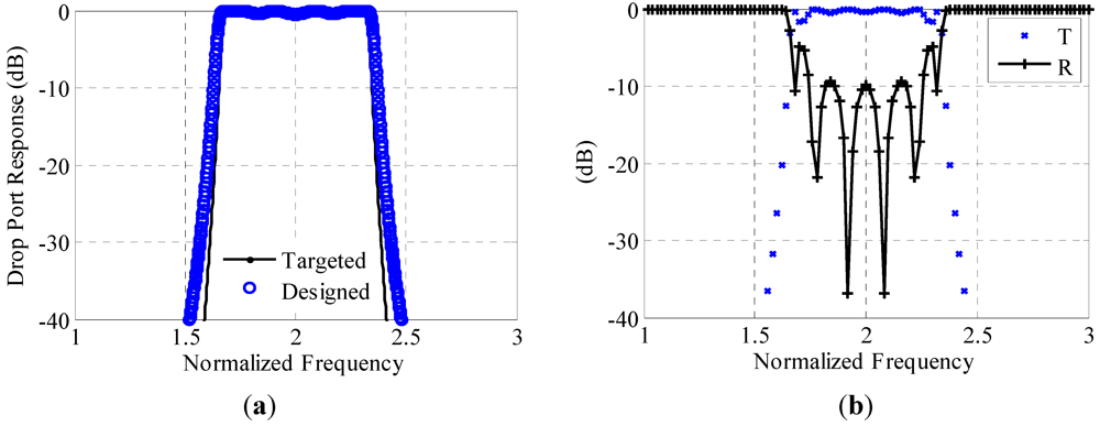
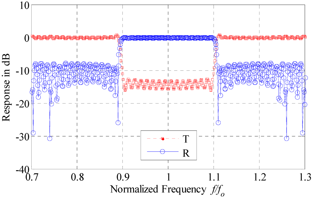
Figure 8.
The drop and through response of the optimized structure with 36 microcavities [
27].
Figure 8.
The drop and through response of the optimized structure with 36 microcavities [
27].
For the first example, a filter response with minimum ripples in the passband is obtained. The number of microcavities is 36. The pass band is 1.0
fo around the central frequency
fo. The response of the through and drop port is given in
Figure 8. The length of the cavity
Lc is taken to be one quarter of the central wavelength. For the second example, the length of the cavity is taken to be half the central wavelength. Thus, the response is switched from band pass filter to band stop filter in the through port and vice versa in the drop port. The number of microcavities in this example is 30. The response in the through port has a rejection band of 0.4
fo centered around
fo. This band has a flat response in the drop port as shown in
Figure 9. For third example, a design of 150 rings is obtained for a flat response over 0.2
fo and sharp roll off over 0.01
fo from each side of the transmission band as shown in
Figure 10. The computation time of this example is 1.2 s. However, solving the non convex minimax problem [
30], the computational time for this example is 1.5 × 10
5 s for a starting point in the middle of the feasible domain. This comparison is performed on a 2.2 GHz dual core processor computer with 2.0 GB of RAM. The optimized values of
σ for all examples are given in
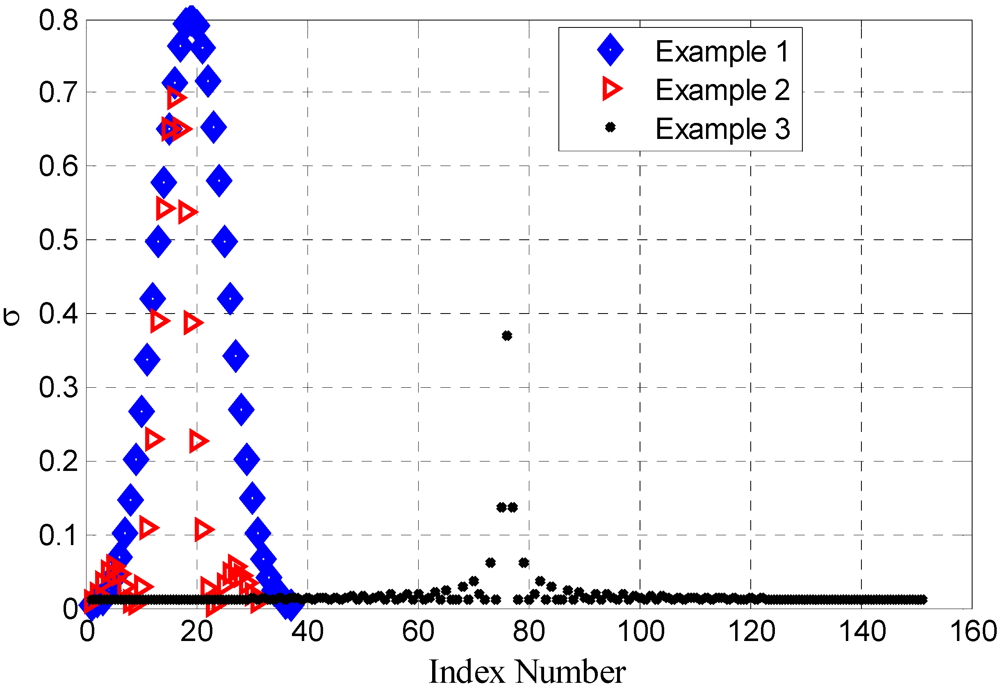
Figure 11. A small change of 10% in the optimized parameters shifts the response by only 6%.
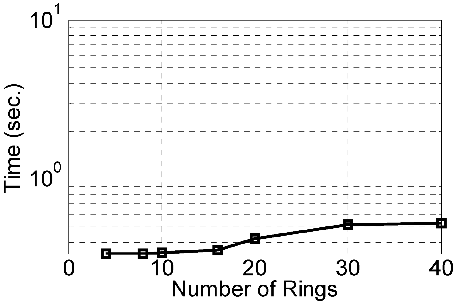
The computational time for different number of coupled rings is show in
Figure 12. It is clear that this problem is linear programming and hence the computational time has small dependence on the number of rings.
Figure 9.
The drop and through response of the optimized structure with 30 microcavities [
27].
Figure 9.
The drop and through response of the optimized structure with 30 microcavities [
27].
Figure 10.
The drop and through response of the optimized structure with 150 microcavities [
27].
Figure 10.
The drop and through response of the optimized structure with 150 microcavities [
27].
Figure 11.
The coupling coefficient of the optimized design of both the 30, 36 and 150 cascaded microcavities [
27].
Figure 11.
The coupling coefficient of the optimized design of both the 30, 36 and 150 cascaded microcavities [
27].
Figure 12.
The computational time for different number of microcavities.
Figure 12.
The computational time for different number of microcavities.
5. Conclusions
Two novel design procedures for filters with large numbers of microcavities were reviewed. These procedures are efficient and simple. Both approaches exploit convex optimization techniques for formulating the design problem. This formulation allows for fast and accurate solution of the design problem. The accuracy and the efficiency of these approaches allow for solving design problems with few hundred of variables in less than one second.

 (1)
(1)
 (2)
(2) (3)
(3) (4)
(4)
 (5)
(5) (6)
(6) (7)
(7) (8)
(8) for all rings. Control of the waveguide to ring and ring to ring scattering parameters allows for a high degree of freedom to achieve different targeted filter responses. The Optical filter realization can be realized from either the through or the drop ports.
  (9)
(9) . A linear approximation of the polynomials B(z) and A(z) dependence on the perturbed through port coupling δσ can thus be formulated. In this case we have:
 (10)
(10) (11)
(11) (12)
(12)
 (14)
(14)

 = [0.25 0.5 0.75 0.75 0.75 0.75 0.75 0.75 0.75 0.5 0.25]T. The perturbation trust region size ζ is set to 0.1. The optimal coupling coefficients are shown in Figure 4. The achieved response and the target response are shown in Figure 5(a). Good match is achieved between the two responses. The response of the ring resonators at the through port (reflectivity) compared to the response at the drop port (transmissivity) is shown in Figure 5(b).

 (15)
(15) (16)
(16) (17)
(17) (18)
(18) where
where  is a real and periodic even function. It is thus sufficient to only consider
  .
. (19)
(19) In Equation (19), the last constraint is added to ensure the physical realization of the designable coupling coefficients.