Abstract
Application fields of micromachined devices are growing very rapidly due to the continuous improvement of three dimensional technologies of micro-fabrication. In particular, applications of micromachined sensors to monitor gas and liquid flows hold immense potential because of their valuable characteristics (e.g., low energy consumption, relatively good accuracy, the ability to measure very small flow, and small size). Moreover, the feedback provided by integrating microflow sensors to micro mass flow controllers is essential to deliver accurately set target small flows. This paper is a review of some application areas in the biomedical field of micromachined flow sensors, such as blood flow, respiratory monitoring, and drug delivery among others. Particular attention is dedicated to the description of the measurement principles utilized in early and current research. Finally, some observations about characteristics and issues of these devices are also reported.
1. Introduction
The measurement of gas and liquid flowrates is an essential requirement in many industrial and commercial applications. In 1975 Hayward estimated there are more than one hundred different types of sensors with a mode of operation based on almost any physical domain [1]. Although several large scale flowmeter types are commercially available, the continuous development of three dimensional techniques of micro-fabrication, with consequent cost reduction and quality improvement, has rapidly extended the market of micromachined flow sensors. The growing interest in research activities related to MEMS is demonstrated by the vast scientific literature and the several hundred companies specifically dedicated to micromachined systems. This growth is mainly due to some crucial advantages of micromachined flow sensors compared to large-scale ones, such as better dynamic characteristics, low power consumption, reduced mass, small size, and cost-effectiveness thanks to batch-fabrication, among other attributes. Although often associated to silicon, because of its frequent use, its economical characteristics and its desirable mechanical properties, micromachining has been performed on several materials including metals, polymers and glasses. The concept of micro-electro-mechanical systems (MEMSs) is still considered to be an emerging technology, but it was born in the early sixties [2], and almost fourteen years (1974) passed until a milestone study appeared, describing the first integrated silicon-based sensor for gas flow measurement [3]. A high growth of research works in the field of MEMS and micromachined flow sensors took place in the eighties and about a decade was needed to develop the integration of many microfluidic devices into a single chip (e.g., micro pumps, valves and flow sensors). Given that microflow devices have very small volume, the result of this challenge was a new class of micromachined flow sensors with an integrated flow micro channel [4]; which Petersen introduced for the first time into this design [5].
The small size and certain valuable characteristics (e.g., high sensitivity, accuracy and precision, low power consumption) coupled with the chance of providing a better outcome for the patients and lower health care cost, make the potential of micro-fabricated devices in medical applications enormous. In fact, some medical fields, ranging over a wide variety of applications in surgical, diagnostic devices and therapeutic areas, are involved in the continuous expansion of micromachined devices [6]. The vast majority of MEMS implemented in biomedical applications are sensors for monitoring many physical parameters such as pressure, acceleration, and fluid flow among others. They are commonly used in orthopedic research field in the study of muscles and patient’s posture, in the monitoring of blood flow, in the measurement of pressure, such as intravascular blood pressure [7], in microsurgery [8], bladder and intraocular applications [9] and in measurement of cerebro-spinal fluid pressure [10]. They are also utilized to monitor the outcome of abdominal aortic aneurysms surgery [11], in the long term monitoring of prosthetic devices, in respiratory monitoring to measure gas flows in spirometric devices [12], to diagnose salivary gland [13] and stomach diseases [14], and in microfabricated drug delivery devices [15]. In this review we do not exhaustively present each application of micromachined sensors in the biomedical field, rather we focus our attention on some applications of micro flow sensors in the monitoring of physiological parameters or used as a feedback in delivery microsystems [16].
This paper is divided into subsections where a concise description of the measurement principle of micromachined flow sensors is presented along with the main biomedical applications. A detailed analysis of sensor’s performances and principles of measurement are also reported.
We will follow the most common classification for micromachined flow sensors, based on the working principles, that distinguishes two groups: the former contains flow sensor based on heat exchange, named “thermal flow sensors”; all others flow meters, based on different working principles of thermal exchange, are grouped into the so-called “non-thermal flow sensors” group. This classification is a consequence of the huge number of thermal-based flow sensors reported in the literature [4]. In the following two sections, both groups of micro flow sensors and their use in specific medical applications are reported. The performances of the sensing methods are also presented.
2. Thermal Flow Sensors
The principles of measurement of thermal flow sensors include transport principles of three of the major branches of physics, based on mechanical-thermal-electrical transport phenomena: the interaction between the measurand (mechanical parameter) and the core of the sensing element, heated by Joule effect (electrical phenomenon), causing a thermal exchange (thermal phenomenon). Therefore, the mechanical measurand modulates, through thermal exchange, one parameter of the sensing element; the modulation produces an output voltage signal, as schematically reported in Figure 1.
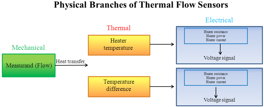
Figure 1.
Physical domains and transport phenomena of thermal flow sensors. (Adapted from [17]).
Thermal flow sensors are usually divided in two subgroups:
- (a) Hot wire or hot element anemometers. These thermal flow sensors are based on convective heat exchange taking place when the fluid flow passes over the sensing element (hot body). They are normally designed to operate in constant temperature mode or in constant current mode. The former approach requires the adjustment of the current through the hot body in order to keep the sensing element temperature constant: the higher the flow rate, the higher is the current value to establish the thermal equilibrium, which represents an indirect measurement of the flow rate. In the second mode, the current in the hot body is held at a constant value. In this approach, the equilibrium temperature of hot body is modulated by the fluid flow, therefore its electrical impedance variation, caused by heat exchange, represents an indirect measurement of the flow rate;
- (b) Calorimetric sensors. These thermal flow sensors are based on the monitoring of the asymmetry of temperature profile around the hot body which is modulated by the fluid flow. Therefore, they use one or more temperature sensing elements placed close to the heater (e.g., Pt100, thermopile).
A further principle is based on the flow dependence of time of flight taken by a heat pulse over a known distance, although it is rarely mentioned in published papers [4].
The first integrated silicon anemometer was presented by van Putten et al. [3]. The same author found a technical solution to drift, by using an integrated double bridge anemometer [18]. The higher performances obtained by Tai et al. [19] and the fabrication of the first flow sensor with integrated micro channel [20], encouraged the interest of researchers in the development of micromachined flow sensors. This is confirmed by numerous and interesting works in the eighties and nineties, which presented several flow sensors with various principles of measurement and performances [17,21,22,23,24,25]. During the last decade the interest of the scientific community is still growing and some works with valuable peculiarities (e.g., multi-range sensors to facilitate the measurement of both low and high gas velocity, very low power consumption sensors, miniaturized sensors) have been reported [26,27,28,29]. For example Glaninger et al. fabricated a thermal flow sensor using a thin film germanium thermistor with a wide range of measurement (±0.01 m∙s−1 to ±200 m∙s−1) and a response time of less than 20 ms [30]. Other interesting works, which have introduced technical solutions to improve some sensor characteristics (e.g., accuracy, sensitivity, and range of measurement), have been published in the last few years [31,32,33,34].
In summary, this family of sensors shows heterogeneous performances:
- - range of measurement. Often reported in terms of velocity, since anemometers measure one point flow velocity, ranges from fraction of cm∙s−1 to several tens of m∙s−1;
- - response time. In the last decade, response time has been considerably improved: it progressed, within a few years, by ranging from 1 s to almost 10 s [35] to values lower than 100 µs [36];
- - power consumption. Also the power consumption covers a wide range: some sensors need several hundreds of mW, on the other hand, some papers describe sensors with a consumption of fractions of mW [37];
- - sensor size. The improvement of techniques of fabrication allows the design of sensors with all three dimensions smaller than 100 µm.
The main advantages of thermal flow sensors are high sensitivity and the wide measurement range; moreover the introduction of solutions to thermally isolate the sensing element is essential to improve some characteristics (e.g., accuracy). The drawbacks of many thermal flow sensors are substantially related to the non-linearity of the calibration curve: although it could represent a valuable characteristic because of the abovementioned high sensitivity at low flow rates, on the other hand, non-linearity causes an appreciable sensitivity decrease with fluid flow. In some cases, a further issue is related to possible presence of dust or humidity in gas flow that strongly affects sensor accuracy.
In the following section a detailed description of micromachined thermal flow sensors utilized in some biomedical applications is reported. The measurement principles of the sensors, and their performances are analyzed.
2.1. Thermal Flow Sensors: Biomedical Applications
In artificial ventilation, continuous monitoring of gas flow and volume is essential to deliver precise amount of gas to patient with the aim to reduce risks of iatrogenic diseases, such as barotrauma and volutrauma. Air volume delivered is quite often estimated by time integration of the flow signal, therefore, commercially available mechanical ventilators are equipped with flowmeters, whose accuracy assumes crucial importance. A variety of sensors is used in this application, such as Fleisch pneumotachographs, ultrasonic flowmeters, and hot wire or hot film anemometers [38]. As the above mentioned characteristics match the critical characteristics required (i.e., good accuracy, short response time, small dead space, and small fluid dynamic resistance), in the last decade some papers describing micromachined flow sensors for respiratory monitoring appeared.
A silicon integrated thermal flow sensor for respiratory applications was presented by van Putten et al. [39]. This sensor shows some valuable characteristics satisfying the requirements of the particular application field: short response time (from 40 ms to 60 ms), essential to monitor the variable respiratory flow, range of measurement (from −60 L∙min−1 to +60 L∙min−1) covering all flow rate values of interest, low temperature (−1.5%/°C) and gas composition sensitivity (<2%), fundamental characteristic because of the marked variation of temperature and gas composition between inspiratory and expiratory flows. Finally, it also allows discriminating flow direction, which is contrary to many thermal transducers [40]. The same authors developed an integrated multisensor microsystem applying silicon MEMS technology for general lung diagnostics [41]. The sensor is a thermal anemometer, based on the measurement of a thermal gradient induced into a heated silicon plate as a function of gas flow. It provides measurement of peak expiratory flow with a rise time of less than 10 ms (useful to diagnose asthma and chronic obstructive pulmonary diseases), temperature and pressure (integrated in one silicon chip), and gas relative humidity.
Since an inadequate gas conditioning can lead to adverse outcomes, particularly critical in infant and neonates [42], a humidity sensor was integrated with an air flow sensor (an integrated hot wire anemometer micromachined on a single chip of silicon) for application in neonatal ventilation [43]. Authors adopted a solution to enhance temperature sensitivity of the hot body resistance: a deep impurity was used instead of an ordinary shallow one in the semiconductor. This approach allowed the increase of the electrical resistance sensitivity to temperature, being modeled as:
 (1)
(1)instead of
 (2)
(2)where B and C are two constants, E is the activation energy of the impurity and K the Boltzmann constant.
The results reported in the abovementioned research, the common use of hot wire anemometers in commercially available mechanical ventilators, and the growing interest in MEMS applications, encouraged some researchers to develop micromachined multipurpose flow sensors [44]. Relevant examples are the use of thermal flow sensors in spirometry for monitoring expiratory and inspiratory gases to estimate some indexes to diagnose asthma and chronic obstructive pulmonary diseases [45]: Laghrouche et al. realized a hot wire sensor, made of a thin polycrystalline silicon film, with a response time strongly dependent on hot wire size (from 367 µs down to 100 µs), a low power consumption (<10 mW) and with a wide measurement range (up to 179 L∙min−1) [46]; Hedrich et al. described a thermal flow sensor for spirometric devices for long-term monitoring of patients in home-care applications. The sensor allowed diagnosing sleep-specific respiration disturbances that are a risk factor for basic cardiovascular diseases [47]. The sensing element (Figure 2(a)) provided a short response time (about 2 ms), wide flow range (up to about 400 L∙min−1), low power consumption (<10 mW), and moreover a solution to prevent the condensation of vapor contained in the respiratory gases was developed [12]. Chiu et al. developed a thermal flowmeter for portable spirometers with a flow range up to 180 L∙min−1, an uncertainty level lower than 3%, as recommended by the American Thoracic Society, and a power consumption of about 40 mW [48]. Kaltas et al. proposed a thermal type sensor for respiratory monitoring with dimensions 1.4 mm × 0.9 mm, range of measurement from −200 L∙min−1 to +200 L∙min−1, and a time constant of about 1.5 ms [49]. Shikida et al. developed a thermal flow sensor used as a tool in a bronchoscope for monitoring trans-bronchially aspired air flow. The anemometer, operating in constant temperature mode, was able to measure flow up to 2 L∙min−1 and showed a response time of about 100 ms [50]. The same author designed an anemometer for evaluating nasal respiration with a measurement range up to 2 L∙min−1 and a rise time of about 260 ms [51].
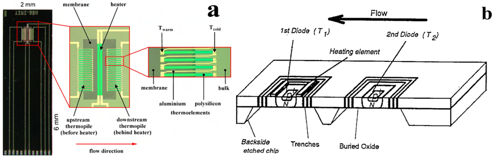
Figure 2.
Micromachined flow sensor principle of measurement. (a) Thermal flow sensor based on the use of thermopile (adapted from [12]); (b) thermal flow sensor with diode as hot body. (Adapted from [52]).
The monitoring of blood flow or velocity is also an application field where micromachined technology has been used. Kersjes et al. developed a sensor with two temperature sensitive diodes (sensitivity 2.1 mV∙K−1) to implement the principle of hot-wire anemometry (Figure 2(b)): one diode, heated by a polysilicon resistor, was placed on a silicon membrane [52]; another unheated diode measured the environmental temperature. The aim of their work was the monitoring of cardiac output (CO), i.e., the amount of blood volume ejected by one ventricle in unit of time. CO value provides an indication of ventricular function; therefore its monitoring is an important component in the hemodynamic management of both critically ill patients and patients with suspected cardiovascular disease. The authors tested the sensor in a large diameter vessel (2 cm) in a range covering typical value of CO (up to 10 L∙min−1). Goosen et al. proposed a preliminary study to monitor blood flow (with velocity up to 21 cm∙s−1) by a calorimetric thermal sensor [53], later they integrated an oxygen saturation sensor [54]. These sensors were developed to be utilized in minimally invasive therapy or in interventional radiology where a number of measurements are required; therefore multi-sensor chip finds wide application [55]. Shear stress sensors, contained in the family of thermal sensors, were introduced to monitor shear stress acting on the lumen of a vessel that is relevant to some diseases, e.g., low shear stress predisposes the development of atherosclerosis [56,57].
Drug delivery systems are the object of intense research to bypass some drawbacks of commonly adopted techniques, in particular when the performances of conventional approaches are suboptimal in terms of efficacy, pain, and safety. The release of drugs, traditionally performed by oral, pulmonary, transdermal delivery or by injection, often requires a high accuracy of drug amount delivered to obtain an optimum therapeutic effect. The development of micromachined sensors, actuators, valves, micropumps and systems using biocompatible materials, along with some advantages shown by implantable infusion systems, has encouraged the introduction of micromachined drug delivery systems that seems to be able to improve the therapeutic effect of drugs. The increasing interest in the field of drug delivery microsystems and their enormous potential, has encouraged the development of novel microdevices or components, such as microneedles, micropumps, microvalves, and implantable drug delivery microdevices [58]. In this scenario, microvalves to perform the flow control, but also measuring devices, such as micromachined flow sensors, are commonly utilized.
The main characteristics (i.e., measurement principle, range of measurement, rise or response time, power consumption, and medical field of application) of the micromachined flow sensors described in the current section are reported in Table 1.

Table 1.
Performances and medical application field for micromachined thermal flow sensors.
| Reference | Measurement Principle | (1) Range of measurement | Power consumption | Application field |
|---|---|---|---|---|
| (2) Rise (tr) or response (τ) time | ||||
| Ma et al. [43] | Thermal Anemometer | (1) up to 90 cm∙s−1 | No data | Respiratory monitoring in neonatal ventilation |
| (2) τ ≈ 1 µs | ||||
| van Putten et al. [39] | Thermal Anemometer | (1) −60 L∙min−1 to +60 L∙min−1 | No data | Respiratory flow measurement |
| (2) tr ranging from 40 ms to 60 ms | ||||
| van Putten et al. [41] | Thermal Anemometer | (1) up to 20 L∙min−1 | No data | Pulmonary function diagnostics |
| (2) tr < 10 ms | ||||
| Laghrouche et al. [46] | Thermal Anemometer | (1) up to 170 L∙min−1 | <10 mW | Spirometer |
| (2) τ ranging from 100 µs to 367 µs | ||||
| Hedrich et al. [12] | Calorimetric Sensor | (1) up to 400 L∙min−1 | <10 mW | Spirometer |
| (2) τ < 2 ms | ||||
| Chiu et al. [48] | Thermal Anemometer | (1) up to 180 L∙min−1 | ≈40 mW | spirometer |
| (2) no data | ||||
| Kaltsas et al. [49] | Thermal Anemometer | (1) −200 L∙min−1 to +200 L∙min−1 | No data | Respiratory monitoring |
| (2) τ ≈ 1.5 ms | ||||
| Shikida et al. [50] | Thermal Anemometer | (1) up to 2 L∙min−1 | No data | Air monitoring in bronchial region |
| (2) τ <100 ms | ||||
| Shikida et al. [51] | Thermal Anemometer | (1) up to 2 L∙min−1 | No data | Nasal respiratory monitoring |
| (2) tr≈260 ms | ||||
| Kersjes et al. [52] | Thermal Anemometer | (1) up to 10 L∙min−1 | <5 mW | Cardiac output monitoring |
| (2) no data | ||||
| Goosen et al. [53] | Calorimetric Sensor | (1) up to 21 cm∙s−1 | No data | Blood flow monitoring |
| (2) no data |
3. Non-Thermal Flow Sensors
All the transducers whose measurement principle is not based on the modulation of thermal exchange by fluid flow are considered non-thermal flow sensors. They are also divided in subgroups. In an exhaustive and recent review, Wang et al. [2] classified non-thermal flow sensors depending on the principle of measurement used: resonating, differential pressure-based, lift-force-based, and cantilever type flow sensors. A brief description of these working principles and a more detailed description of laser Doppler anemometry (LDA) will be provided. This laser measurement technique is of particular interest in medicine (e.g., for blood flow monitoring) and in the last decade the fabrication of integrated laser Doppler flowmeters has been one of the main challenges in micromachined devices.
√ Lift-force, drag-force or cantilever flow sensors
These principles of measurement are based on the force acting on a body located in a fluid flow. Actually, the fluid flow exerts on the body two perpendicular force components: the drag force, Fdrag, i.e., the force acting in the flow direction; and the lift force, Flift, i.e., the force perpendicular to the flow stream. Both are proportional to the square of the mean flow velocity (  ):
):
): (3)
(3)where CD is the drag-force coefficient and CL is the lift-force coefficient, ρ is the fluid density, l and w are the body length and width. CL strongly depends on the angle of attack and is experimentally estimated. The study of Svedin et al. is a milestone in the design of micromachined flow sensors based on lift-force [59,60]: the deflection of two thin plates of single-crystalline silicon induced by the lift force is utilized to modulate the electrical resistances of an array of strain gauges connected in a Wheatstone bridge configuration. In a successive work, Svedin et al. combined the lift-force with a thermal principle of measurement to obtain the detection of flow direction and to improve the sensor sensitivity in a wider range (up to 70 L∙min−1) [61,62]. The lift force is insensitive to flow direction therefore, a dual chip configuration to detect the direction was introduced. Moreover, both thermal and lift-force sensors have a non-linear calibration curve with a considerable difference: thermal flow sensor has high sensitivity at low flow (accordingly to King’s law), whereas the lift-force principle makes sensor’s output increase with flow, therefore both principles were combined to increase the sensitivity in a wide flow rate range.
√ Drag-force or cantilever type flow sensors
As far as it concerns drag-force-based and cantilever flow sensors, an interesting work was presented by Gass et al. where the drag force exerted by fluid flow onto a cantilever beam allowed to measure flow ranging from 5 µL∙min−1 to 500 µL∙min−1 [63]. Similar approaches were used by Su et al. [64] and Kao et al. [65]. A cantilever flow sensor, allowing velocity measurement up to 45 m∙s−1, with a response time of about 0.53 s and a power consumption of 0.02 mW, was realized by Wang et al. [66]. They upgraded their valuable work by integrating temperature compensation and the ability to discriminate flow direction [67], as shown in Figure 3. The principle of measurement, based on the deflection of a cantilever operated by fluid flow, allows a voltage output obtained by a Wheatstone bridge with resistance of piezoresistors depending on the cantilever deflection, thus on the flow value. Recently, the development of multi-sensor integrated technology is a trend in MEMS followed by Du et al., among others, who integrated a previously designed drag force sensor [68] with a thermal one to realize a micro-wind sensor. Also in this case, the sensor utilizes the thermal part for low wind velocity (<2 m∙s−1), the mechanical one for high velocity (>2 m∙s−1) [69].
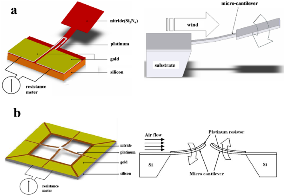
Figure 3.
(a) Design of cantilever type sensor (adapted from [66]); (b) Schematic of cantilever sensor able to detect flow direction (adapted from [67]).
√ Differential pressure-based flow sensors
In the early twentieth century, this measurement principle has been introduced in large-scale gas flowmeters with different approaches (e.g., orifice or Venturi flowmeters and Fleisch pneumotachographs), where flow estimation is carried out by the measurement of pressure drop across an ad hoc designed sensing element (an orifice or a linear resistance). When a fluid flow passes through a duct, or over a surface, it produces a pressure drop depending on the mean velocity of the fluid. Several micromachined sensors relying on this principle are fabricated: as an example, Berbering et al. developed a differential-based sensors realizing flow-velocity detection up to 23 m∙s−1 by measurement of the pressure difference between the stagnant fluid pressure in front of the sensor and static pressure of fluid around the sensor [70]. The pressure gradient causes the deflection of a membrane that constitutes one of the two plates of a capacitor, and results in a decrease of capacitance between the electrodes converted in a voltage signal by an electrical circuit.
√ Resonating flow sensors
In 1989, the influence of temperature on the resonance frequency of a vibrating membrane was used to develop a micromachined flow sensor with a 2 µm thick membrane [71]. Successively, the same authors realized a resonating microbridge to improve sensor performance [72]. Microflow sensors based on resonance frequency shift of the output signal are relatively robust against noise levels and signal drift. Different approaches were used to realize these sensors, for example, Seo et al. [73] have recently presented a self-resonant flow sensor were the vibration of a microcantilever is modulated by surface stress acting on the beam due to fluid drag force. A cantilever, placed in the fluid stream, undergoes mechanical oscillations related to the vortex shedding frequency. This phenomenon, known as “flow-induced or vortex induced vibration”, can be expressed as:
 (4)
(4)being fs the vortex shedding frequency, V the flow velocity, St the Strouhal number, and D the characteristic length of the cantilever. In MEMS application the fluid flow can be turbulent or the cantilever beam can be smaller than the boundary layer of the fluid flow, and the cantilever beam oscillates by the “turbulence-induced vibrations”. In this case the microstructure vibration is modulated by the resonant frequency of the cantilever itself and shows a resonance frequency depending on the axial force induced by the fluid drag force. The vibrations are sensed by a piezoelectric material placed on a silicon cantilever beam.
√ Laser Doppler flowmeter
This working principle will be described in more detail because of its large use in the medical field and its potential in applications related to blood flow monitoring. The design of these sensors is based on the Doppler shift described by Christian Doppler in 1842. The phenomenon is due to the interaction between an electromagnetic or acoustic wave and a moving object: the wave is reflected back showing a frequency different from the incident one. The frequency shift, Δf, depends on the velocity of the moving object, therefore, if the object moves within the fluid flow, it represents a flow indirect measurement:
 (5)
(5)Equation (5) gives a direct relation between the frequency shift and the velocity (U) of the moving object; λ is the wavelength of the incident wave, α the angle between the axis of the incoming wave and the observer, and β the angle between the moving object velocity direction and the bisector of the angle between the axis of the incoming wave and the segment connecting the object and the observer, as depicted in Figure 4(a).
The “dual-beam approach” is often implemented to improve sensor’s performances: the radiation is split into two beams and successively crossed into an intersection region through a mirror (Figure 4(b)). This region defines a sampling volume, placed into the fluid flow, where the particle velocity is measured. In the intersection region, an interference pattern, characterized by interference fringes, is produced. When a particle passes through the fringes, it causes periodic variations of the intensity of the scattered light [74]. The particle speed can be expressed as a function of the frequency fluctuations (fr) of the scattered intensity and of the distance between two contiguous fringes (γ) as follows:
 (6)
(6)being θ the angle between the two beams.
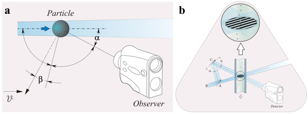
Figure 4.
(a) Schematic representation of the Doppler phenomenon; (b) schematic representation of laser Doppler differential approach: A, beam splitter; B, incident wave; C, mirror (adapted from [74]).
Some works were carried out to realize compact laser Doppler-based instruments [75]. The aim was to create devices that integrate all the optical components of the laser Doppler flowmeter. This approach allows avoiding the main drawback affecting the most common techniques used to conduct the laser light in the site of measurement and from the site to the photodetector (e.g., by a fiber optic): i.e., the need of alignment between individual optical components [76].
In summary, some non-thermal flow sensors present the main drawback of the response’s dependence on the fluid density.
3.1. Non-Thermal Flow Sensors: Biomedical Applications
Several non-thermal flow sensors have been designed to be used in respiratory monitoring. The measurement principle based on lift-force presents some valuable characteristics for application in spirometry or mechanical ventilation. First of all, it fulfills the important requirement of an associated low pressure loss. The design proposed by Svedin et al. [60] allows compliance with these requirements and describes a sensor with good output symmetry and good sensitivity in a wide range of flow rates (Figure 5(a)). In order to improve the sensitivity, Svedin designed a “dual principle” sensor which used a thermal measurement principle (two hot chips were integrated to detect flow direction) and a lift-force-based flow sensor. As the two approaches have their highest respective sensitivity in different regions, the thermal principle is used at low flow (up to 7 L∙min−1) and lift-force principle at high flow (up to 50 L∙min−1).
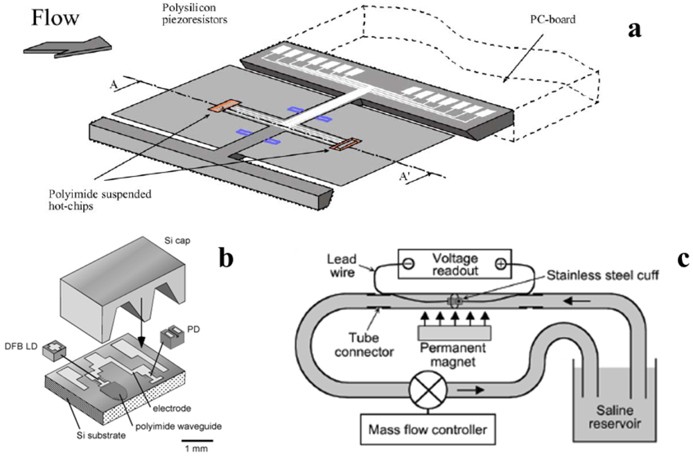
Figure 5.
(a) Principle of measurement of “dual principle” (lift-force and thermal) flowmeter (adapted from [62]); (b) Sensing element of integrated laser Doppler flowmeter. (Adapted from [76]); (c) Principle of measurement of electromagnetic flowmeter (adapted from [77]).
Recently, Wei et al. [78] proposed a sensor based on the deformation of a miniaturized cantilever due to fluid flow. The deformation was detected by a Wheatstone bridge, consisting of a resistive sensor and three external resistances, with an output voltage quite linear with air flow velocity in the range 0.4 m∙s−1 up to about 2.5 m∙s−1.
Fiber optic-based flow sensors can be broadly classified as intrinsic sensors, if the sensing element is the fiber itself, and extrinsic sensors, that use the fiber as a medium. Different fiber-optic based [79,80] and optoelectronic [81] flow sensors are developed for use in medical field, such as in mechanical ventilation. Mireles proposed a novel extrinsic fiber-optic sensor, based on an approach used in clinical practice to monitoring pressure: it presents as secondary element a micromachined Fabry-Perot cavity placed at the end-tip of a fiber optic constituted by two high reflecting mirrors [82]. The mirror placed in front of the fiber tip is movable and the fluid flow affects it. Therefore, distance between the two mirrors is modulated by the drag force caused by fluid flow acting on the movable one; the interferometric technique allows estimating the fluid flow. Although Mireles did not report sensor performances, this design could be very useful in medical applications where the need of small dimensions (e.g., in invasive procedures) is required.
Micromachined flow sensors incorporating several measurement principles have found large application for measuring blood flow rates in some tissues, i.e., perfusion. As perfusion is a primary parameter in the local transport of oxygen, nutrients, heat, et cetera, its monitoring is useful in several diagnoses.
With the aim to monitor blood velocity in coronary arteries to determine the efficacy of balloon catheterization, Rapoport et al. developed a sensor using a microdynamic rotor as sensing element [83]. The microrotor, fabricated with silicon microfabrication technology, changes its rotation rate with fluid velocity. The discrimination threshold for liquid flow monitoring was approximately 300 cm∙s−1 and trials were performed up to 550 cm∙s−1.
Takahata et al. designed and tested a micromachined cuff to monitor blood flowing into a vessel [77]. The sensor has an electromagnetic working principle based on Faraday’s law: when a polarizable liquid passes through a magnetic field, a voltage is generated across the flow channel (Figure 5(c)). By considering blood flowing perpendicularly to the magnetic and electrical sense axes, the induced voltage is maximized and can be expressed as:
 (7)
(7)with FEM being the induced voltage, B the magnetic field, and QB the blood flow. The FEM is detected by an intraluminal cuff, fabricated by a lithography-compatible approach, with two electrodes insulated from each other by dielectric links formed in the cuff; B is provided by a permanent magnet. The sensor was tested from 40 cm∙s−1 up to 180 cm∙s−1 showing good linearity between flow and the induced voltage.
After the introduction of laser Doppler velocimetry for blood flow (1972), numerous approaches have been introduced to implement laser Doppler velocimetry to monitor blood flow. With the aim of designing a wearable device, Higurashi et al. developed a laser Doppler flowmeter for measuring blood flow [76]. The hybrid integrated blood flowmeter for real-time monitoring of microcirculation presented by Higurashi eliminated the issue of positioning and alignment of individual optical components in three dimensions. In fact, the lightweight and small sensor (3 mm2 that is one-hundredth the size of conventional probe-type instruments) integrates the light source and the detector on a silicon substrate with a fluorinated polyimide waveguide (Figure 5(b)). In vivo experimental trials for measuring blood perfusion at the fingertip were performed. Recently, Kimura et al. designed a novel integrated laser Doppler blood flowmeter with the aim of bypassing certain issues of the conventional laser Doppler flowmeter with fiber optics in clinical practice (positioning and alignment, fragility, etc.) [84]. In this work, the light source and the detector are mounted in cavities fabricated with an anisotropic silicon etching technique and are covered with a silicon lid partially processed into a microlens. The working principle is based on the interference between light backscattered from static tissue (not relevant for Doppler shift) and the light backscattered from red blood cells flowing in blood capillary that undergoes the Doppler shift. Their interference generates an optical beat signal that modulates the photocurrent generated by the detector. The blood flow can be estimated by the frequency of the photocurrent signal.
The main characteristics (i.e., measurement principle, range of measurement, rise or response time, power consumption, and medical field of application) of the micromachined non thermal flow sensors used in medical application and described in the current section are reported in Table 2.
Table 2.
Performances and medical application field for micromachined non-thermal flow sensors.
| Reference | Measurement Principle | (1) Range of measurement | Power consumption | Application field |
|---|---|---|---|---|
| (2) Rise (tr) or response (τ) time | ||||
| Svedin et al. [62] | Lift-force, thermal anemometry | (1) up to ±50 cm·s−1 | No data | Respiratory monitoring |
| (2) no data | ||||
| Wei et al. [78] | Cantilever type | (1) 0.5 m·s−1 to +2.5 m·s−1 | No data | Respiratory monitoring |
| (2) no data | ||||
| Mireles [82] | Interferometric technique | (1) no data | No data | Medical application |
| (2) no data | ||||
| Rapoport et al. [83] | Microrotor-based | (1) from 300 cm·s−1 to 550 cm·s−1 | No data | Blood flow monitoring |
| (2) no data | ||||
| Takahata et al. [77] | Electromagnetic-based | (1) from 40 cm·s−1 to 180 cm·s−1 | No data | Flow monitoring in vessels, bile duct, etc. |
| (2) no data | ||||
| Higurashi et al. [76] | Laser Doppler flowmeter | (1) no data | No data | Monitoring capillary microcirculation |
| (2) no data | ||||
| Kimura et al. [84] | Laser Doppler flowmeter | (1) up to 14 mm·s−1 | No data | Monitoring capillary microcirculation |
| (2) no data |
4. Conclusions
Micromachined devices represent the next phase in industrial measurement and monitoring. At present, these devices are mainly implemented in industrial applications such as automotive ones. Although their introduction in medical field is just at the beginning, they demonstrate enormous potential for surmounting common issues encountered in medicine and are considered as an attractive area of research. Interest is encouraged by the valuable characteristics of micromachined devices with a number of possibilities to be discovered in the near future: miniaturization is an essential requirement in minimally-invasive medical applications. Moreover, good accuracy and fast response are also crucial factors for monitoring physiological parameters in surgical, diagnostic and therapeutic areas. At present micromachined sensors are mainly used in medicine for pressure monitoring, but this technology could revolutionize some medical applications. The aim of this review is to give an idea of the potentialities of micromachined flow sensors in medical applications without presuming to exhaustively present all the numerous publications on this topic.
In particular their introduction could improve the flow rate monitoring of blood, in large vessels or microcirculation, and respiratory flows. They present some crucial characteristics to be used in these fields, such as short response time, good sensitivity and accuracy; moreover, their small size could introduce some advantages in minimally invasive measurements. Regardless of their huge potentialities, the greatest challenges for commercial success of this technology on the medical market are cost reduction and robust design.
Acknowledgments
This work has been carried out under the financial support of Regione Lazio in the framework of the ITINERIS2 project (CUP code F87G10000120009). Authors gratefully acknowledge ITAL GM s.r.l. for the precious support provided. Authors would like to thank Sonia Rubegni for her precious collaboration in the realization of figures.
References
- Miller, R.W. Introduction to the differential producer. In Flow Measurement Engineering Handbook, 3rd; Miller, R.W., Ed.; McGraw-Hill: New York, NY, USA, 1996; Sections 7.1–7.5. [Google Scholar]
- Wang, Y.H.; Chen, C.P.; Chang, C.M.; Lin, C.P.; Lin, C.H.; Fu, L.M.; Lee, C.Y. MEMS-based gas flow sensors. Microfluid. Nanofluid. 2009, 6, 333–346. [Google Scholar] [CrossRef]
- van Putten, A.F.P.; Middlehoek, S. Integrated silicon anemometer. Electron. Lett. 1974, 10, 425–426. [Google Scholar] [CrossRef]
- Nguyen, N.T. Micromachined flow sensors—A review. Flow Meas. Instrum. 1997, 8, 7–16. [Google Scholar] [CrossRef]
- Petersen, K.; Brown, J. High-Precision, High-performance mass-flow sensor with integrated laminar flow micro-channels. In Proceedings of Technical Digest of the 3rd International Conference of Solid-State Sensors and Actuators (Transducers ’85), Philadelphia, PA, USA, 11–14 June 1985; pp. 361–363.
- Polla, D.L.; Erdman, A.G.; Robbins, W.P.; Markus, D.T.; Diaz-Diaz, J.; Rizq, R.; Nam, Y.; Brickner, H.T. Microdevices in medicine. Ann. Rev. Biomed. Eng. 2000, 2, 551–576. [Google Scholar] [CrossRef]
- Totsu, K.; Haga, Y.; Esashi, M. Ultra-miniature fiber-optic pressure sensor using white light interferometry. J. Micromech. Microeng. 2005, 15, 71–75. [Google Scholar] [CrossRef]
- Zhang, X. Silicon microsurgery-force sensor based on diffractive optical MEMS encoders. Sens. Rev. 2004, 24, 37–41. [Google Scholar] [CrossRef]
- Katuri, K.C.; Asrani, S.; Ramasubramanian, M.K. Intraocular pressure monitoring sensors. IEEE Sens. J. 2008, 8, 12–19. [Google Scholar]
- Yoon, H.J.; Jung, J.M.; Jeong, J.S.; Yang, S.S. Micro devices for a cerebrospinal fluid (CSF) shunt system. Sens. Actuat. A: Phys. 2004, 110, 68–76. [Google Scholar] [CrossRef]
- Allen, M.G. Micromachined endovascularly-implantable wireless aneurysm pressure sensors: From concept to clinic. In Proceedings of the 13th International Conference on Solid-State SensorsActuators and Microsystems (Transducers ’05), Seoul, Korea, 5–9 June 2005; pp. 275–278.
- Hedrich, F.; Kliche, K.; Storz, M.; Billat, S.; Ashauer, M.; Zengerle, R. Thermal flow sensors for MEMS spirometric devices. Sens. Actuat. A: Phys. 2010, 162, 373–378. [Google Scholar] [CrossRef]
- Ziegler, C.M.; Steveling, H.; Seubert, M.; Muhling, J. Endoscopy: A minimally invasive procedure for diagnosis and treatment of diseases of the salivary glands: Six years of practical experience. Br. J. Oral Maxillofac. Surg. 2005, 42, 1–7. [Google Scholar]
- Lee, Y.S.; Song, K.D.; Huh, J.S.; Chung, W.Y.; Lee, D.D. Fabrication of clinical gas sensor using MEMS process. Sens. Actuat. B: Chem. 2005, 108, 292–297. [Google Scholar]
- Hilt, J.Z.; Peppas, N.A. Microfabricated drug delivery devices. Int. J. Pharm. 2005, 306, 15–23. [Google Scholar] [CrossRef]
- Damiani, C.; Klein, S.; Wuttig, D.; Nestler, B. Measurement and control of ultra-low liquid flowrates for drug delivery application. In Proceedings of the 14th Nordic-Baltic Conference on Biomedical Engineering and Medical Physics, Riga, Latvia, June 2008.
- van Oudheusden, B.W. Silicon thermal flow sensor. Sens. Actuat. A: Phys. 1992, 30, 5–26. [Google Scholar] [CrossRef]
- van Putten, A.F.P. An integrated double bridge anemometer. Sens. Actuat. 1983, 4, 387–396. [Google Scholar] [CrossRef]
- Tai, Y.C.; Howe, R.T. Polysilicon bridges for anemometer applications. In Proceedings of Technical Digest of the 3rd International Conference of Solid-State Sensors and Actuators (Transducers ’85), Philadelphia, PA, USA, 11–14 June 1985; pp. 354–357.
- Petersen, K.; Brown, J. High-precision, high-performance mass-flow sensor with integrated laminar flow micro-channels. In Proceedings of Technical Digest of the 3rd International Conference of Solid-State Sensors and Actuators (Transducers ’85), Philadelphia, PA, USA, 11–14 June 1985; pp. 361–363.
- Lammerink, T.S.J.; Tas, N.R.; Elwenspoek, M.; Fluitman, J.H.J. Micro-liquid flow sensor. Sens. Actuat. 1993, 37–38, 45–50. [Google Scholar]
- Tai, Y.C.; Muller, R.S. Lightly-doped polysilicon bridge as a flow meter. Sens. Actuat. 1988, 15, 63–75. [Google Scholar] [CrossRef]
- Löfdahl, L.; Stemme, G.; Johansson, B. Silicon based flow sensors for mean velocity and turbulence measurements. Exp. Fluids 1992, 12, 270–276. [Google Scholar]
- Nguyen, N.T.; Dötzel, W. Asymmetrical locations of heaters and sensors relative to each other using heater arrays: A novel method for designing multi-range electrocaloric mass-flow sensors. Sens. Actuat. A: Phys. 1997, 62, 506–512. [Google Scholar] [CrossRef]
- Kuttner, H.; Urban, G.; Jachimowicz, A.; Kohl, F.; Olcaytug, F.; Goiser, P. Microminiaturized thermistors arrays for temperature gradient, flow and perfusion measurements. Sens. Actuat. A: Phys. 1991, 25, 641–645. [Google Scholar]
- Chen, J.; Fan, Z.; Zou, J.; Engel, J.; Liu, C. Two-dimensional micromachined flow sensor array for fluid mechanics studies. J. Aerosp. Eng. 2003, 16, 85–97. [Google Scholar] [CrossRef]
- Sabate, N.; Santander, J.; Fonseca, L.; Gracia, I.; Cané, C. Multi-range silicon micromachined flow sensor. Sens. Actuat. A: Phys. 2004, 110, 282–288. [Google Scholar] [CrossRef]
- Dijkstra, M.; de Boer, M.J.; Berenschot, J.W.; Lammerink, T.S.J.; Wiegerink, R.J.; Elwenspoek, M. Miniaturized thermal flow sensor with planar-integrated sensor structures on semicircular surface channels. Sens. Actuat. A: Phys. 2008, 143, 1–6. [Google Scholar] [CrossRef]
- Cubukcu, A.S.; Zernickel, E.; Buerklin, U.; Urban, G.A. A 2D thermal flow sensor with sub-mW power consumption. Sens. Actuat. A: Phys. 2010, 163, 449–456. [Google Scholar] [CrossRef]
- Glaninger, A.; Jachimawicz, A.; Kohl, F.; Chabicovsky, R.; Urban, G. Wide range semiconductor flow sensors. Sens. Actuat. A: Phys. 2000, 85, 139–146. [Google Scholar] [CrossRef]
- Yu, B.; Gan, Z.; Cao, S.; Xu, J.; Liu, S. A micro channel integrated gas flow sensor for high sensitivity. In Proceedings of 11st Intersociety Conference on Thermal and Thermomechanical Phenomena in Electronic Systems (ITHERM ’08), Orlando, FL, USA, 28–31 May 2008; pp. 215–220.
- Yu, B.; Gan, Z.; Xu, J.; Liu, S. The study of a micro channel integrated gas flow sensor. Chin. J. Electron. 2009, 18, 435–438. [Google Scholar]
- Lee, C.Y.; Wen, C.; Hou, H.; Yang, R.J.; Tsai, C.H.; Fu, L.M. Design and packaging of MEMS based flow-rate and flow-direction microsensor. Microfluid. Nanofluid. 2009, 6, 363–371. [Google Scholar] [CrossRef]
- Chow, W.W.Y.; Qu, Y.; Li, W.J.; Tung, S.C.H. Integrated SWCNT sensors in micro-wind tunnel for air-flow shear-stress measurement. Microfluid. Nanofluid. 2010, 8, 631–640. [Google Scholar] [CrossRef]
- Kälvesten, E.; Vieider, C.; Löfdahl, L.; Stemme, G. An integrated pressure-flow sensor for correlation measurements in turbulent gas flows. Sens. Actuat. A: Phys. 1996, 52, 51–58. [Google Scholar] [CrossRef]
- Liu, C.; Huang, J.B.; Zhu, Z.; Jiang, F.; Tung, S.; Tai, Y.C.; Ho, C.M. A micromachined flow shear-stress sensor based on thermal transfer principles. J. Microelectronmed. Syst. 1999, 8, 90–99. [Google Scholar] [CrossRef]
- Makinwa, K.A.A.; Huijsing, J.H. A smart wind sensor using thermal sigma-delta modulation Techniques. Sens. Actuat. A: Phys. 2002, 97, 15–20. [Google Scholar] [CrossRef]
- Bates, J.H.T.; Turner, M.J.; Lanteri, C.J.; Jonson, B.; Sly, P.D. Measurement of flow and volume. In Infant Respiratory Function Testing,1st ed.; Stokes, J., Sly, P.D., Tepper, R.S., Morgan, W.J., Eds.; Wiley-Liss Inc.: New York, NY, USA, 1996; pp. 81–116. [Google Scholar]
- van Putten, M.J.A.M.; van Putten, M.H.P.M.; van Putten, A.F.P.; Pompe, J.C.; Bruining, H.A. A silicon bidirectional flow sensor for measuring respiratory flow. IEEE Trans. Biomed. Eng. 1997, 44, 205–208. [Google Scholar] [CrossRef]
- Schena, E.; Silvestri, S. A transistor based air flow transducer for thermohygrometric control of neonatal ventilator application. Rev. Sci. Instrum. 2008, 79, 104301:1–104301:7. [Google Scholar]
- van Putten, A.F.P.; van Putten, M.J.A.M.; van Putten, M.H.P.M.; van Putten, P.F.A.M. Multisensor microsystem for pulmonary function diagnostics. IEEE Sens. J. 2002, 2, 636–643. [Google Scholar] [CrossRef]
- Verta, A.; Schena, E.; Silvestri, S. Mathematical model and minimal measurement system for optimal control of heated humidifiers in neonatal ventilation. Med. Eng. Phys. 2010, 32, 475–481. [Google Scholar] [CrossRef]
- Ma, Y.; Ma, S.; Wang, T.; Fang, W. Air-flow sensor and humidity sensor application to neonatal infant respiration monitoring. Sens. Actuat. A: Phys. 1995, 49, 47–50. [Google Scholar] [CrossRef]
- Randjelovic, D.; Petropoulos, A.; Kaltsas, G.; Stojanovic, M.; Lazic, Z.; Djuric, Z.; Matic, M. Multipurpose MEMS thermal sensor based on thermopiles. Sens. Actuat. A: Phys. 2008, 141, 404–413. [Google Scholar] [CrossRef]
- Miravitlles, M.; Andreu, I.; Romero, Y.; Sitjar, S.; Altes, A.; Anton, E. Difficulties in differential diagnosis of COPD and asthma in primary care. Br. J. Gen. Pract. 2012, 62, e68–e75. [Google Scholar]
- Laghrouche, M.; Montes, L.; Boussey, J.; Ameur, S. Low-cost embedded spirometer based on a micro machined polycrystalline thin film. Flow Meas. Instrum. 2011, 22, 126–130. [Google Scholar] [CrossRef]
- Eckert, D.J.; Malhotra, A. Pathophysiology of adult obstructive sleep apnea. Proc. Am. Thorac. Soc. 2008, 15, 144–153. [Google Scholar]
- Chiu, N.F.; Hsiao, T.C.; Lin, C.W. Low power consumption design of micro-machined thermal sensor for portable spirometer. Tamkang J. Sci. Eng. 2005, 8, 225–230. [Google Scholar]
- Kaltsas, G.; Nassiopoulou, A.G. Gas flow meter for application in medical equipment for respiratory control: Study of the housing. Sens. Actuat. A: Phys. 2004, 110, 413–422. [Google Scholar]
- Shikida, M.; Naito, J.; Yokota, T.; Kawabe, T.; Hayashi, Y.; Sato, K. A catheter-type flow sensor for measurement of aspired- and inspired-air characteristics in the bronchial region. J. Micromech. Microeng. 2009. [Google Scholar] [CrossRef]
- Shikida, M.; Yokota, T.; Naito, J.; Sato, K. Fabrication of a stent-type thermal flow sensor for measuring nasal respiration. J. Micromech. Microeng. 2010. [Google Scholar] [CrossRef]
- Kersjes, R.; Liebscher, F.; Spiegel, E.; Manoli, Y.; Mokwa, W. An invasive catheter flow with on-chip CMOS readout electronics for the on-line determination of blood flow. Sens. Actuat. A: Phys. 1996, 54, 563–567. [Google Scholar] [CrossRef]
- Goosen, J.F.L.; French, P.J.; Sarro, P.M. Pressure and flow sensor for use in catheters. In Proceedings of SPIE, Santa Clara, CA, USA, 20–21 September 1999.
- Goosen, J.F.L.; French, P.J.; Sarro, P.M. Pressure, Flow and oxygen saturation sensors on one chip for use in catheters. In Proceedings of the 13th Annual International Conference on Micro Electro Mechanical Systems (MEMS ’00), Miyazaki, Japan, 23 January 2000.
- Tanase, D.; Goosen, J.F.L.; Trimp, P.J.; French, P.J. Multi-parameter sensor system with intravascular navigation for catheter/guide wire application. Sens. Actuat. A: Phys. 2002, 97–98, 116–124. [Google Scholar]
- Soundararajan, G.; Rouhanizadeh, M.; Yu, H.; DeMaio, L.; Kim, E.S.; Hsiai, T.K. MEMS shear stress sensors for microcirculation. Sens. Actuat. A: Phys. 2005, 118, 25–32. [Google Scholar]
- Laghrouche, M.; Montes, L.; Boussey, J.; Meunier, D.; Ameur, S.; Adanee, A. In situ calibration of wall shear stress sensor for micro fluidic application. In Proceedings of Eurosensors XXV, Athens, Greece, 4–7 September 2011.
- Tao, S.L.; Desai, T.A. Microfabricated drug delivery sistems: From particles to pores. Adv. Drug Deliv. Rev. 2003, 55, 315–328. [Google Scholar] [CrossRef]
- Svedin, N.; Stemme, E.; Stemme, G. A new Bi-directional gas-flow sensor based on lift force. In Proceedings of the 9th International Conference on Solid-State Sensors and Actuators (Transducers ’97), Chicago, IL, USA, 16–19 June 1997; pp. 16–19.
- Svedin, N.; Kalvesten, E.; Stemme, E.; Stemme, G. A new silicon gas-flow sensor based on lift force. J. Micromech. Syst. 1998, 7, 303–308. [Google Scholar] [CrossRef]
- Svedin, N.; Kalvesten, E.; Stemme, E.; Stemme, G. A lift force sensor designed for acceleration insensivity. Sens. Actuat. A: Phys. 1998, 68, 263–268. [Google Scholar] [CrossRef]
- Svedin, N.; Kalvesten, E.; Stemme, G. A lift force sensor with integrated hot-chips for wide range flow measurements. Sens. Actuat. A: Phys. 2003, 109, 120–130. [Google Scholar] [CrossRef]
- Gass, V.; van Der Schoot, B.H.; de Rooij, N.F. Nanofluid handling by micro-flow-sensor based on drag force measurements. In Proceedings of 6th IEEE International Workshop on Micro Electromechanical System (MEMS ’93), Fort Lauderdale, FL, USA, 7–10 February 1993; pp. 167–172.
- Su, Y.; Evans, A.G.R.; Brunnschweiler, A.; Ensell, G. Characterization of a highly sensitive ultra-thin piezoresistive silicon cantilever probe and its application in gas flow velocity sensing. J. Micromech. Microeng. 2002. [Google Scholar] [CrossRef]
- Kao, I.; Kumar, A.; Binder, J. Smart MEMS flow sensor: Theoretical analysis and experimental characterization. IEEE Sens. J. 2007, 7, 713–722. [Google Scholar] [CrossRef]
- Wang, Y.H.; Lee, C.Y.; Chiang, C.M. A MEMS-based air flow sensor with a free-standing micro-cantilever structure. Sensors 2007, 7, 2389–2401. [Google Scholar] [CrossRef]
- Ma, R.H.; Wang, D.A.; Hsueh, T.H.; Lee, C.Y. A MEMS-based flow rate and flow direction sensing platform with integrated temperature compensation scheme. Sensors 2009, 9, 5460–5476. [Google Scholar] [CrossRef]
- Du, L.; Zhao, Z.; Pang, C.; Fang, Z. Drag force micro solid state silicon plate wind velocity sensor. Sens. Actuat. A: Phys. 2009, 151, 35–41. [Google Scholar] [CrossRef]
- Du, L.; Zhao, Z.; Fang, Z.; Xu, J.; Geng, D.; Liu, Y. A micro-wind sensor based on mechanical drag and thermal effects. Sens. Actuat. A: Phys. 2009, 155, 66–72. [Google Scholar] [CrossRef]
- Berberig, O.; Nottmeyer, K.; Mizuno, J.; Kanai, Y.; Kobayashi, T. The Prandtl micro flow sensor (PMFS): A novel silicon diaphragm capacitive sensor for flow-velocity measurement. Sens. Actuat. A: Phys. 1998, 66, 93–98. [Google Scholar] [CrossRef]
- Bouwstra, S.; Kemna, P.; Legtenberg, R. Thermally excited resonating membrane mass flow sensor. Sens. Actuat. A: Phys. 1989, 20, 213–223. [Google Scholar] [CrossRef]
- Bouwstra, S.; Legtenberg, R.; Tilmans, H.A.C.; Elwenspoek, M. Resonating microbridge mass flow sensor. Sens. Actuat. A: Phys. 1990, 21, 332–335. [Google Scholar] [CrossRef]
- Seo, Y.H.; Kim, B.H. A self-resonant micro flow velocity sensor based on a resonant frequency shift by flow-induced vibration. J. Micromech. Microeng. 2010. [Google Scholar] [CrossRef]
- Silvestri, S.; Schena, E. Optical-fiber measurement systems for medical applications. In Optoelectronics—Devices and Applications, 1st; Predeep, P., Ed.; InTech: Lexington, KY, USA, 2011; pp. 205–224. [Google Scholar]
- de Mul, F.F.M.; van Spijker, J.; van Der Plas, D.; Greve, J.; Aarnoudse, J.G.; Smits, T.M. Mini laser-Doppler (blood) flow monitor with diode laser source and detection integrated in the probe. Appl. Opt. 1984, 23, 2970–2973. [Google Scholar]
- Higurashi, E.; Sawada, R.; Ito, T. An integrated laser blood flowmeter. J. Lightwave Technol. 2003, 21, 591–595. [Google Scholar] [CrossRef]
- Takahata, K.; Gianchandani, B.; Wise, K.D. Micromachineed antenna stents and cuffs for monitoring intraluminal pressure and flow. J. Micromech. Syst. 2006, 15, 1289–1298. [Google Scholar] [CrossRef]
- Wei, C.L.; Lin, C.F.; Tseng, I.T. A novel MEMS respiratory flow sensor. IEEE Sens. J. 2010, 10, 16–18. [Google Scholar] [CrossRef]
- Battista, L.; Sciuto, S.A.; Scorza, A. Preliminary evaluation of a fiber-optic sensor for flow measurements in pulmonary ventilators. In Proceedings of the 6th Annual International Workshop on Medical Measurements and Applications, Bari, Italy, 30–31 May 2011; pp. 29–34.
- Schena, E.; Saccomandi, P.; Mastrapasqua, M.; Silvestri, S. An optical fiber based flow transducer for infant ventilation: measurement principle and calibration. In Proceedings of the 6th Annual International Workshop on Medical Measurements and Applications, Bari, Italy, 30–31 May 2011; pp. 311–315.
- Saccomandi, P.; Schena, E.; Silvestri, S. A novel target-type low pressure drop bidirectional optoelectronic air flow sensor for infant artificial ventilation: Measurement principle and static calibration. Rev. Sci. Instrum. 2011, 82, 024301:1–024301:9. [Google Scholar]
- Mireles, J. Micromachined sensor design for optical-fiber flow measurement. Sens. Rev. 2005, 25, 33–39. [Google Scholar] [CrossRef]
- Rapoport, S.D.; Reed, M.L.; Weiss, L.E. Fabrication and testing of a microdynamic rotor for blood flow measurements. J. Micromech. Microeng. 1991, 1, 60–65. [Google Scholar] [CrossRef]
- Kimura, Y.; Goma, M.; Higurashi, E.; Sawada, R. Integrated laser Doppler blood flowmeter designed to enable wafer-level packaging. IEEE Trans. Biomed. Eng. 2010, 57, 2026–2033. [Google Scholar] [CrossRef]
© 2012 by the authors; licensee MDPI, Basel, Switzerland. This article is an open-access article distributed under the terms and conditions of the Creative Commons Attribution license (http://creativecommons.org/licenses/by/3.0/).