1. Introduction
In an attempt to address the ever rising demand for high performance compact power source, a new branch of micro-electro-mechanical system called power MEMS has recently been defined
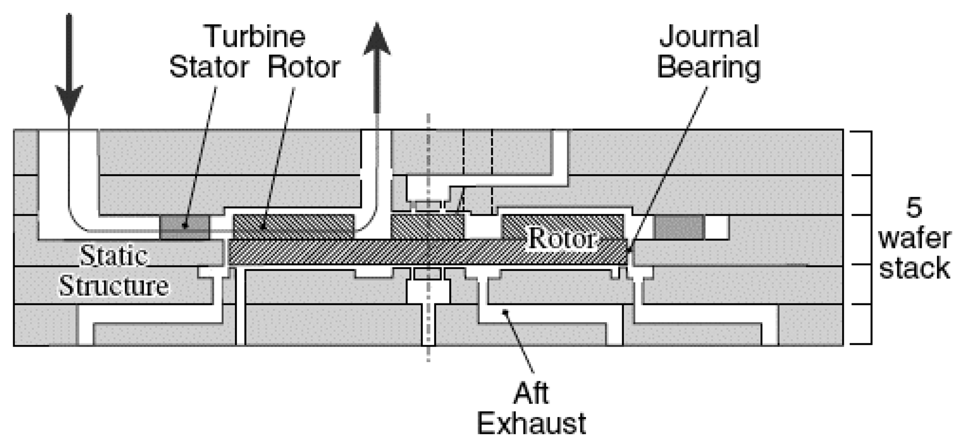
[1, 2]. Among them, the nascent project to develop micro scale gas turbine generators at MIT is specifically targeted for high power density applications. These machines are supported by gas bearings, as shown in
Fig.1, and able to achieve rotation rate of more than one million RPM (revolutions per minute)
[2]. The micro rotor and the micro bearing are fabricated by micro fabrication technology. Different from the traditional rotor system, the micro rotor and the bearing are made of Silicon.
Operating at such high speed, an accurate assessment of the vibration characteristics of the micro rotor system must be made so as to design highly reliable rotary machines and avoid occurrence of dangerous sliding wear and rub impact effect. Thus, the high speed rotor dynamic characteristic of the micro rotor-bearing system is a major concern in the mechanical design of micro motors and such kind of power MEMS. There are many dynamic phenomena and nonlinear problems that can be met for MEMS that may challenge successful operation of these machines. Some researches, which aimed at analyzing and simulating the rotor dynamics in micro rotating machinery
[3, 4], have been done during the past two decades. Piekos
[5] developed a pseudo-spectral method to facilitate orbit simulation of the rotor. Savoulides
[6] constructed a small-scale gas bearing model for the rotor. Wang
[7] analyzed the bifurcation of a rotor supported by a self-acting gas journal bearing, and the analysis focused on the dynamic behavior of the rotor-bearing system. In these researches, the lubricated gas film was mostly treated as continuum flow, and effects of the micro fluid mechanics have not been considered.
One of the most interesting characteristics in micro rotor-bearing systems is that the nature of the lubricated gas flow departs from the continuum flow regime. For a micro gas bearing, the thickness of the gas film is comparable with the gas molecular mean free path. At this scale, the gas layer adjacent to the surface does not satisfy the no-slip velocity boundary condition. Some researchers have made contributions and improvements to this field. Burgdofer
[8] introduced the first-order slip velocity model and derived the modified Reynolds equation. Hsia
[9] and Mitsuya
[10] presented the second-order slip model and the 1.5-order modified Reynolds equation. Huang
[11] discussed the second-order slip effect on the micro gas bearing steady-state operation performance. Y.H Sun
[12] presented analytical investigations of slip flow between the flying head and disk in the hard disk drive. However, these researchers mainly focused on the micro fluid mechanics, and few attentions have been paid to the performance of the micro journal bearing.
In this study, the performance of the micro bearing is evaluated and the stability of the micro rotor system is discussed. The gas velocity slip effect on the solid boundary is taken into account, and the modified Reynolds equation is solved with the finite difference method (FDM). By comparison of performances of the micro gas bearing such as flow rate, gas pressure distribution, load carrying capacity and attitude angle derived from different models, the slip effect on the performances of the bearing is discussed and the second order slip model is chosen to evaluate dynamic characteristics of the system. The linear dynamic coefficients are employed to acquire the linear threshold speed for stable operation, and the dynamic responses of different speed regimes are compared. It is found that, for a micro gas bearing, the velocity slip effect would result in smaller dynamic coefficients. As a result, the stability of the micro rotor system is compromised and the threshold speed for stable operation is pushed upwards.
2. Slip model and Reynolds equation
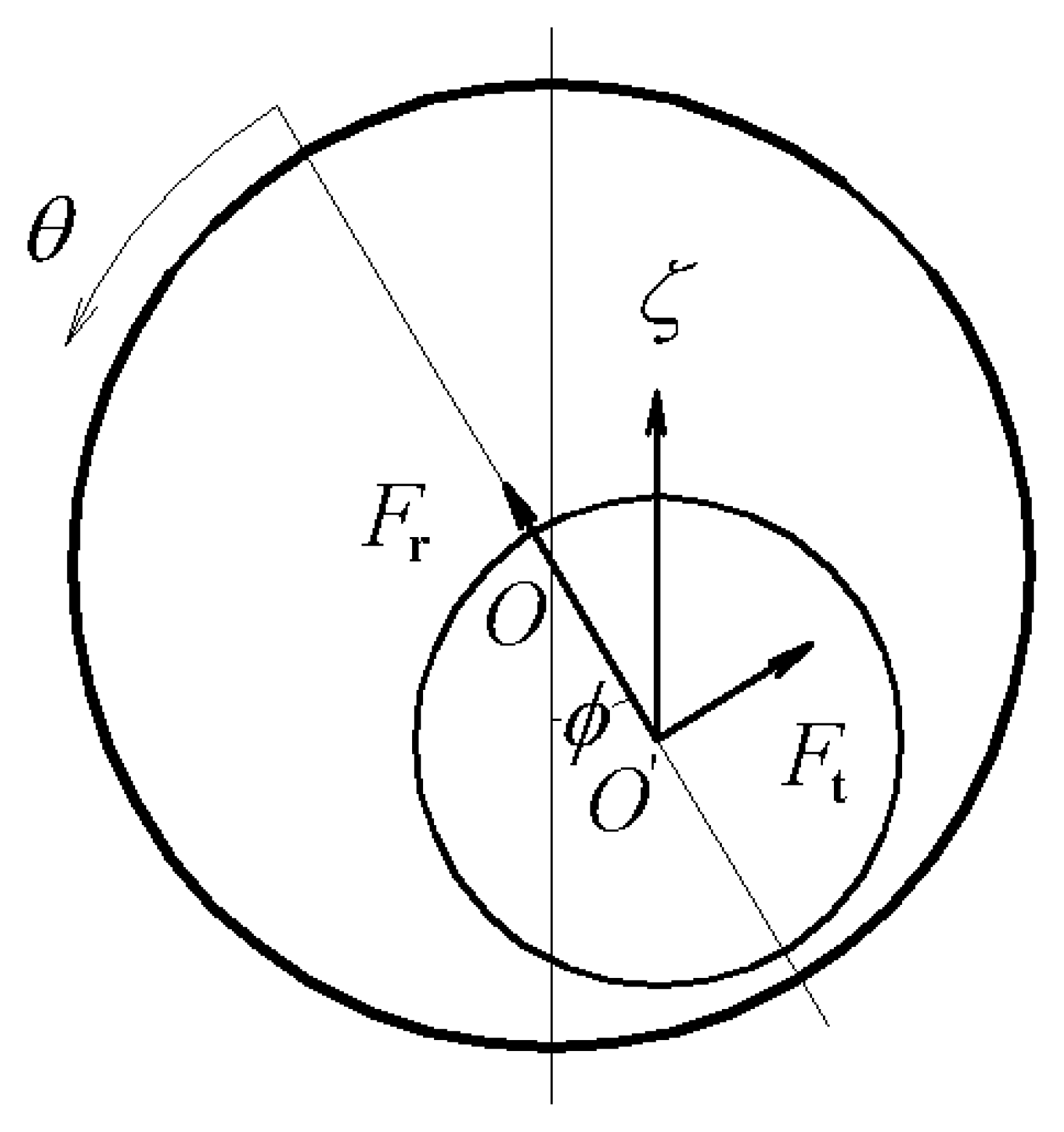
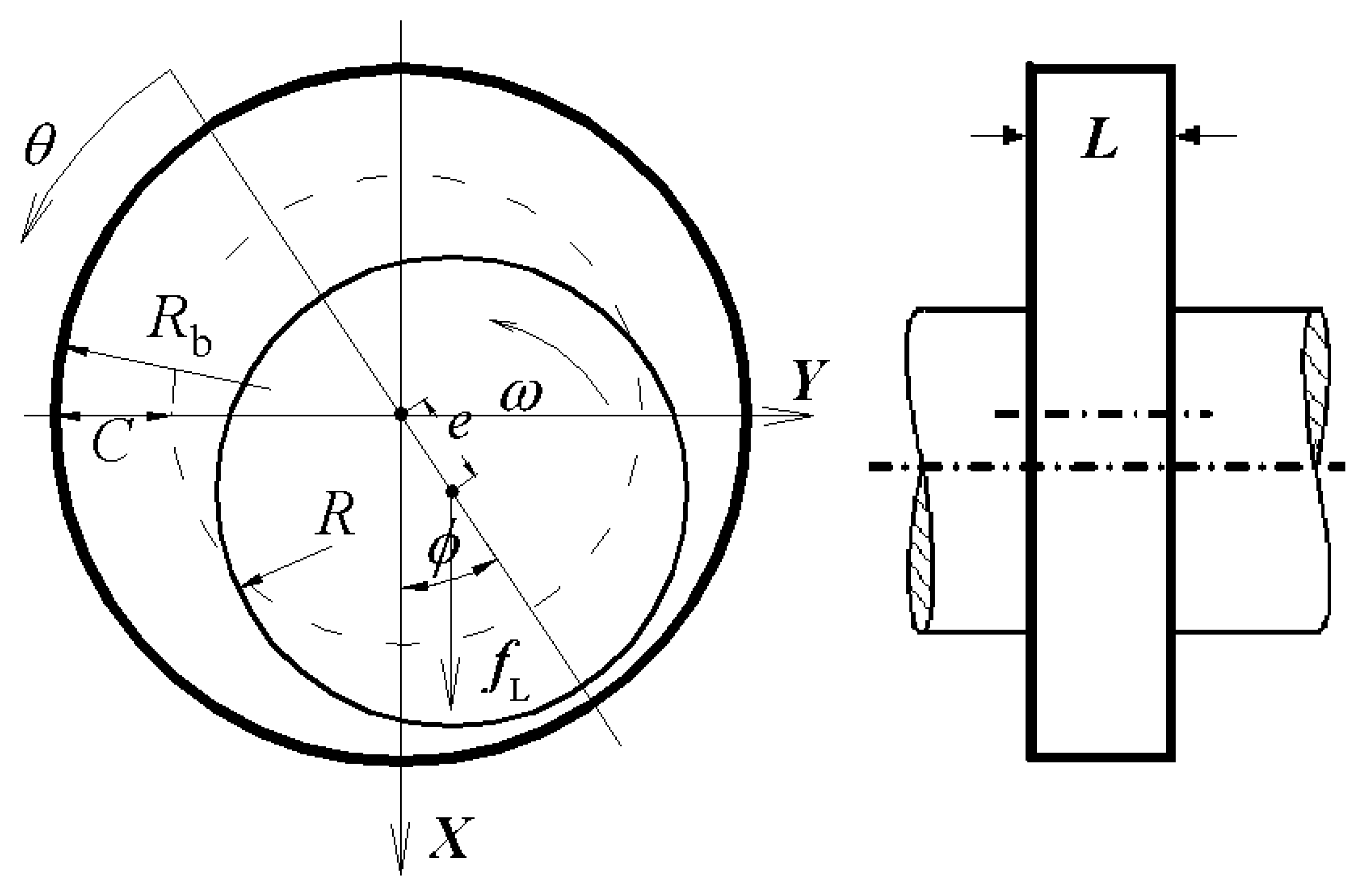
Fig. 2 shows the schematic of a micro gas journal bearing to be investigated. The micro rotor spins at an angular velocity of
ω inside a stationary bushing. The bearing's radius is
Rb, and the rotor's radius
R. When the rotor's center coincides with the bearing's center, the distance between the outer edge of the rotor and the inner edge of the bushing defines the average clearance,
C. The ratio of the clearance to the radius is denoted by
ψ (
ψ=
C/
R). As is shown here in cross sectional view, the bearing is
L in length with both ends either exposed to the ambient or treated with a uniform pressure distribution, denoted by
Pa. Due to constraints dictated by MEMS fabrication technologies, the dimension of the gas journal bearing is chosen as
R=2
mm,
L=
300μm, C=12
μm, from which we could see that the micro journal bearing is very short compared to their macro-scale counterparts. The bearing's length to diameter ratio is 0.075, which is at least one order of magnitude smaller than that in conventional gas bearings. This variation inherently alters the driving flow mechanisms in the micro bearing and consequently the performance of the micro bearing and the stability of the micro rotor system.
The mass of the rotor is denoted by m, and em, known as unbalance eccentricity, defines the distance between the center of mass and center of geometry of the rotor. The external radial force, denoted by fL, exerts on the rotor and pushes the journal center away from the bearing center. The distance between the two centers, known as the eccentricity and denoted by e, is usually normalized by the average clearance and expressed as an “eccentricity ratio” denoted by ε (ε=e/C). A coordinate system is defined such that the X-axis is parallel to the direction of the applied force, while the Y-axis is perpendicular to the applied force. The angle between the X-axis and the line connecting the rotor center and the bearing center defines the attitude angle and is denoted by ϕ.
In view of the length scale of the micro bearing, the thickness of the film would approach 0.1
μm or less. Thus the characteristic length of the gas film is comparable to the mean free path of the gas molecule, and the flow regime could be determined by the Knudsen number, which is defined as
Kn=
λ/
h. Here,
λ is the molecular mean free path, and
h the characteristic length of the gas film. According to the category of Bird
[13], the gas flow in the bearing resides in the slip regime (10
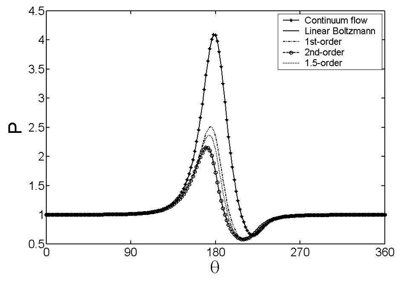
−3 < Kn < 0.1), in which the velocity slip occurs at the solid boundary and the traditional Reynolds equation needs to be modified. If we adopt the first-order slip model, the flow slippage on the surface of the journal and bushing is given as
[8]where σ is the accommodation coefficient relative to momentum, a=(2−σ)/σ the surface correcting coefficient. When the second-order slip model is taken, the flow slippage becomes
[9]And for the 1.5-order slip model, the flow slippage yields
[10]Using the non-dimensional parameters expressed in
Eq.(4), the first order modified Reynolds equation, the second order modified Reynolds equation and the 1.5 order modified Reynolds equation can be written in the non-dimensional form as
Eq. (5),
Eq. (6) and
Eq. (7).
Here,
τ,
p,
θ,
ξ and
h is the dimensionless time, dimensionless pressure, circumferential coordinate, axial coordinate and film thickness respectively. Where
is the bearing number,
μ and
pa viscosity and pressure of the ambient gas respectively.
4. Motion equations and the linear threshold speed
In this discussion, it is assumed that the micro rotor-bearing system is comprised of a rigid rotor and rigid mounted bushing. Also, the rotor is perfectly co-axial with the bushing. Thus, the motion equations of the rotor in the Cartesian coordinates can be written as follows:
where
x and
y are the projection of the rotor displacement onto the X-axis and Y-axis. Likewise,
fx and
fy are components of gas-film force in these two directions.
Eq. (20) can be rewritten in state space form as follows
where
Z1=
X, Z2=
Y, Z3=
X'
, Z4=
Y' are the state variables of the system. And some dimensionless variables are as follows
The gas-film forces are nonlinear function and can be secured by solving the Reynolds equation with FDM. However, in most practical calculations, it is assumed that perturbation of the rotor from its initial position is small enough that the gas-film forces could be considered as linear. Thus the gas-film force increments are modeled by a first-order Taylor expansion
[15, 16] as follows
where
ΔFx and
ΔFy are the bearing force increments,
Kij and
Dij the dimensionless stiffness and damping coefficient respectively. Substituting
Eqs. (23) into
Eqs. (21), and assume that the unbalance ratio is zero (
β=0), the system's free vibration equations can be derived in matrix form:
Subject matrix
A to eigenvalue evaluation so as to investigate the linear dynamic stability of the system. The real part of each eigenvalue,
δ, is the damping rate and corresponds to how quickly a perturbation of the rotor decays.
δ<0 implies a decay motion (stable), while
δ>0 implies a diverging motion (unstable). There are four eigenvalues of matrix
A. We only consider the one with the biggest positive real part, because it represents the most dangerous mode and can be observed in an experimental measurement. At the threshold of instability, the matrix
A has an eigenvalue with real part equal to zero, and the following equations can be derived
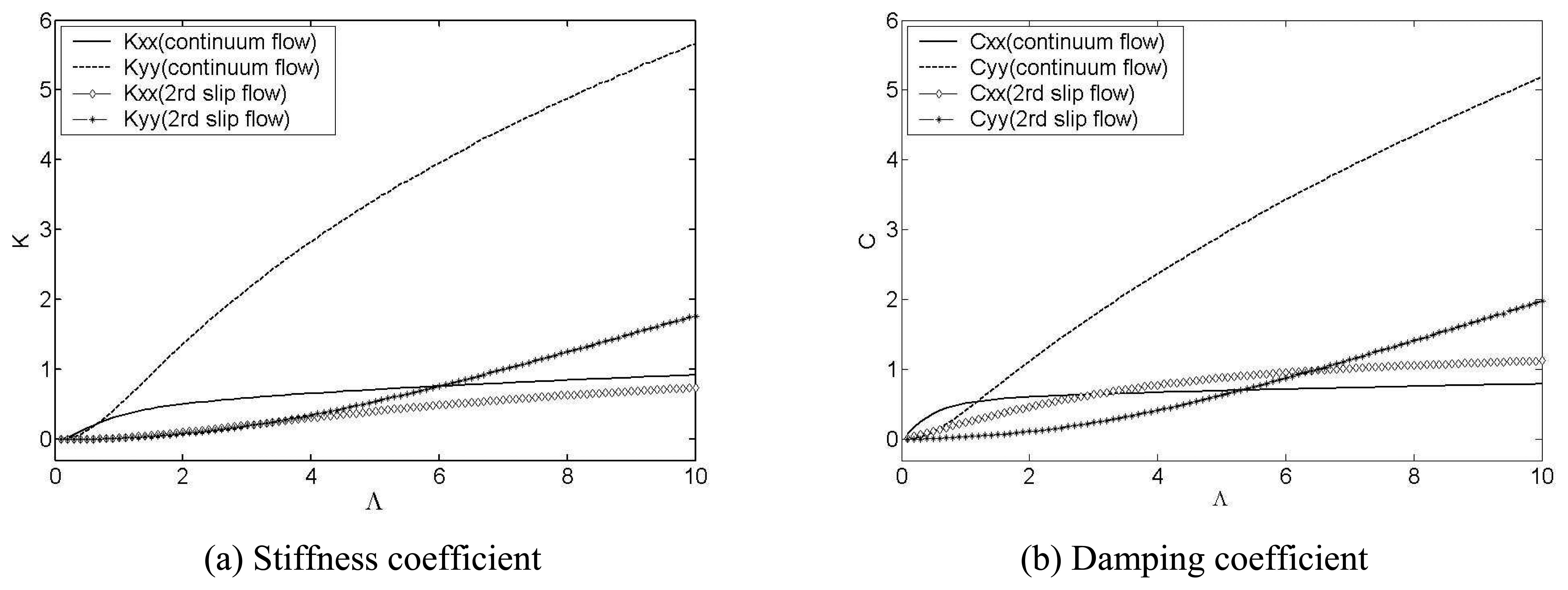
Figure 8 presents the comparison of the stiffness and damping coefficients between the continuum model and second order slip model when the eccentricity ratio is 0.9. It can be seen that the dynamic coefficients increase with the increase of the bearing number, indicating the enhancement of the stability of the micro rotor system.
Referring to
Fig. 8, the dynamic coefficients of the second order slip flow are much lower than those of the continuum flow. From the discussion in section 3, it is known that the second order slip flow predicts more accurate solutions for the micro gas bearing, and the continuum flow assumption lead to mistaken results. Furthermore, it is implied that the continuum flow assumption will underestimate the threshold speed for stable operation. Combining
Eq.(25) and
Eq.(26) with results shown in
Fig.8, the threshold speed can be obtained. For the continuum flow, the stable threshold speed of the bearing system is close to the point Λ = 0.3 when the eccentricity is 0.9. Considering the slip effect, the threshold speed raise to Λ = 6.3.
5. Dynamic responses of the rotor-bearing system
The numerical simulation of the rotor dynamical response can be achieved by solving the Reynolds equation and the motion equation subsequently.
Eq. (21) for dynamical motion can be solved by fourth-order Rouge-Kutta method, and the displacements and velocities time series for rotor can thus be obtained.
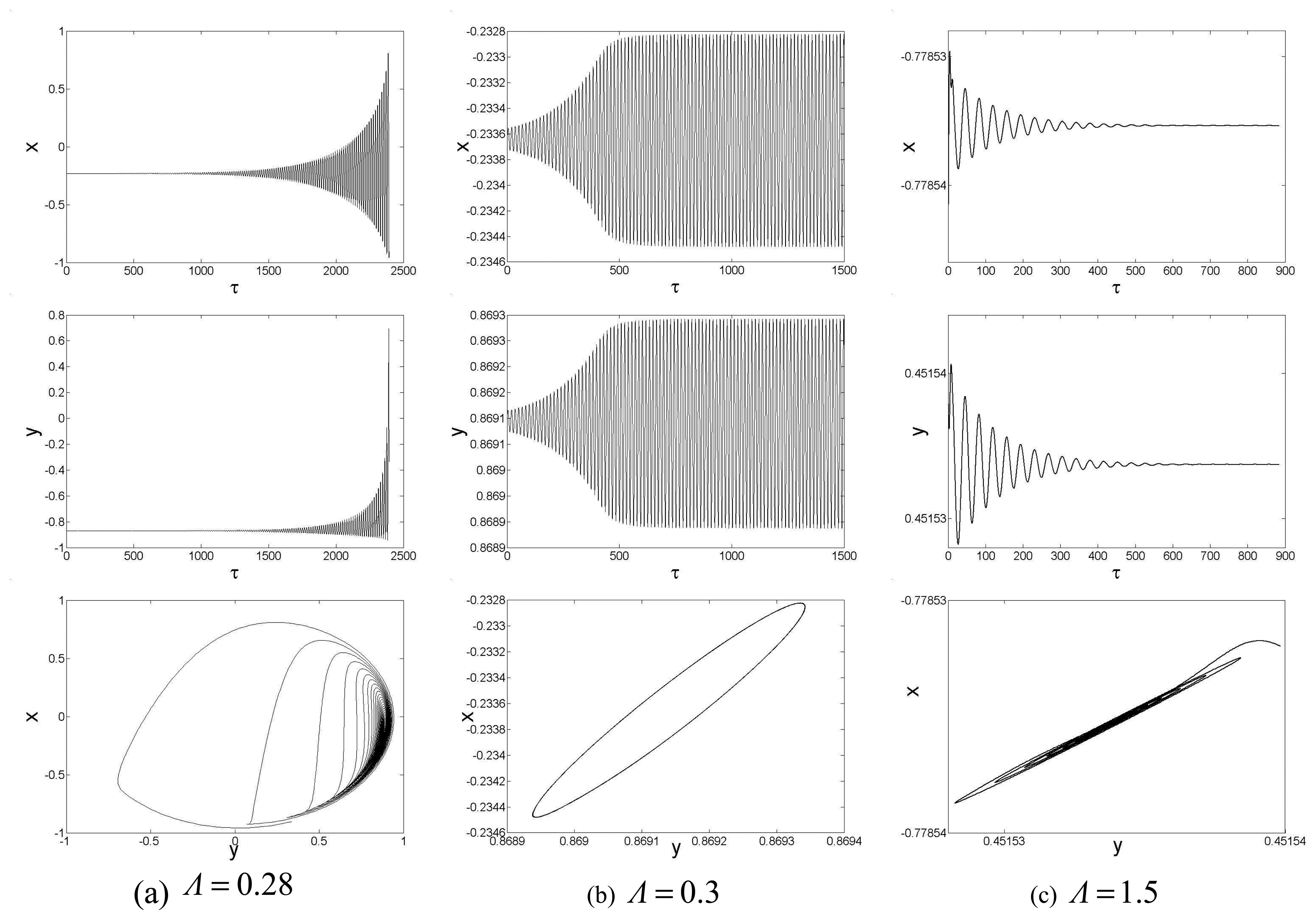
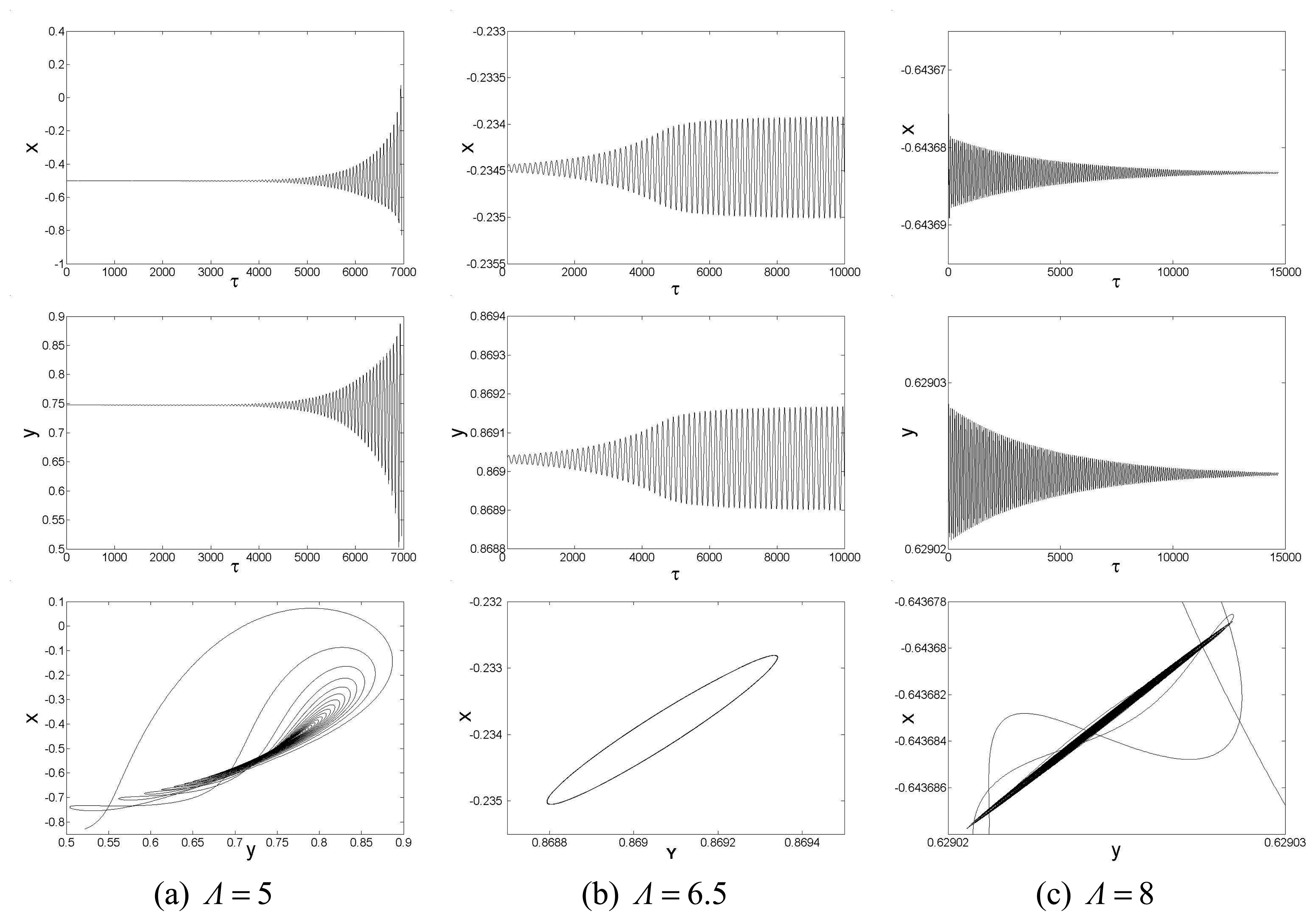
Given a slight disturbance, a balanced rotor will converge to its static equilibrium position or whirl around the static equilibrium if the rotational speeds is above the threshold speed. And it will crash into the bushing when the rotational speed is less than the threshold speed. With the continuum model assumption, the dynamic responses of the micro gas bearing at different rotational speed are shown in
Fig.9 respectively. When the second slip model is adopted, the responses are different from the continuum flow case, as shown in
Fig.10.
By comparison between
Fig.9 and
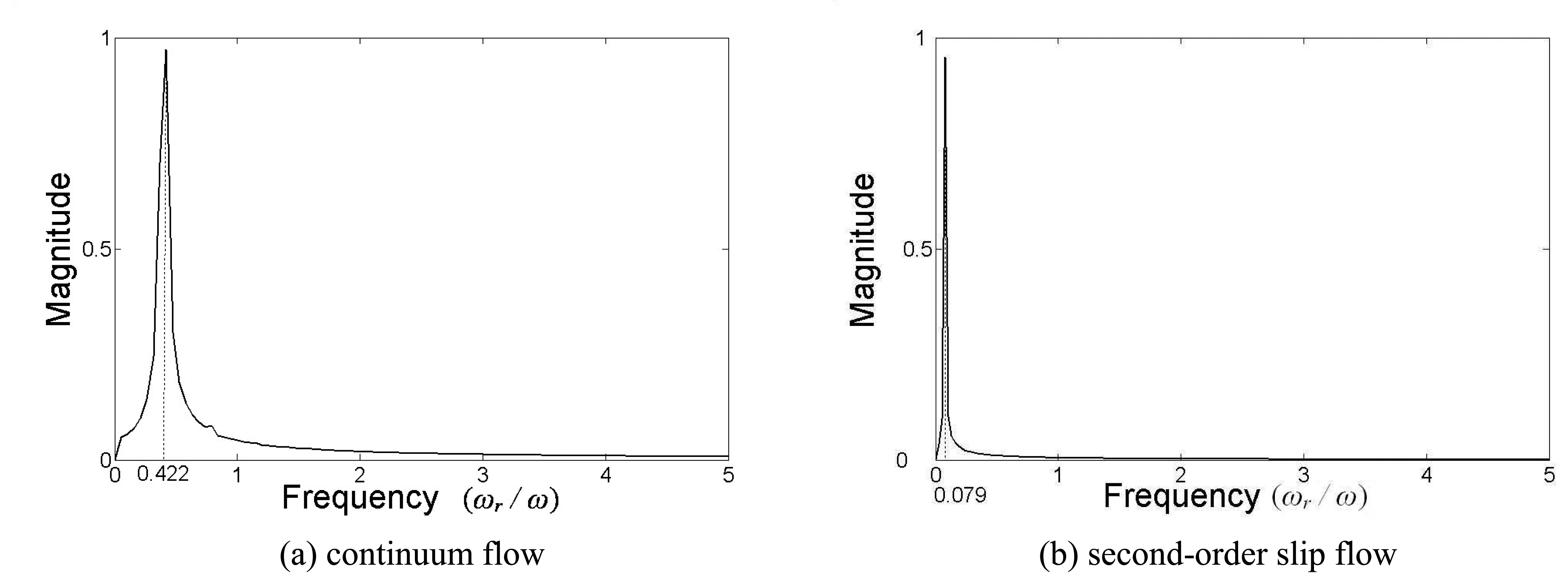
Fig.10, it can be seen that not only the threshold speed of the stable operation is raised, but also the dynamical responses are different when employing the second-order slip model. It is found that due to the slip effect, the micro rotor needs much more time to reach a stable operation or to crash into the bushing. Furthermore, the oscillation period of the whirl motion is prolonged when the second slip flow model is adopted. As a result, the whirl frequency is reduced due to the slip effect, as shown in
Fig.11.
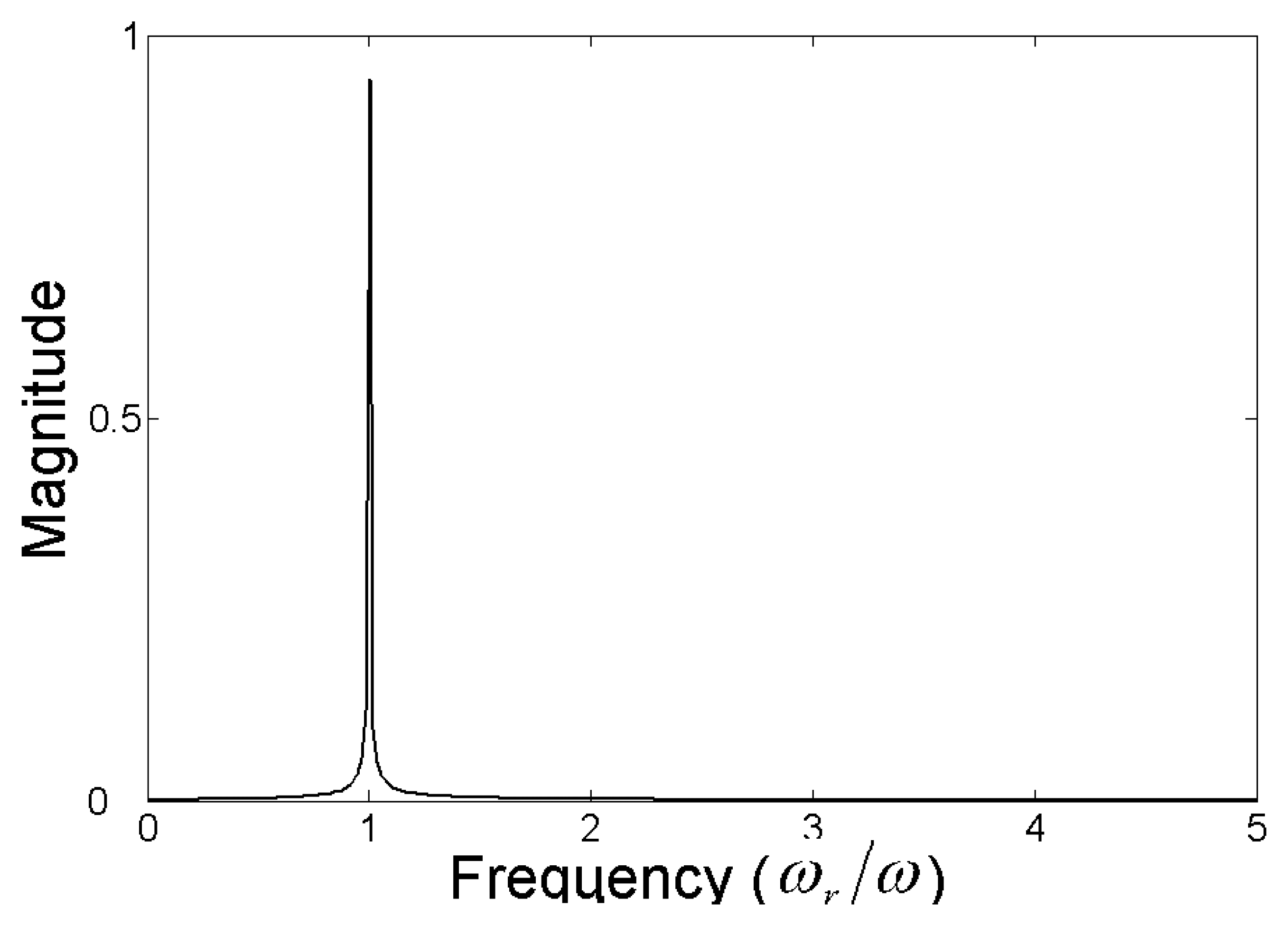
In this discussion, the whirl is caused by the gas film force. It can be seen from
Fig.11 that the whirl frequency is decreased due to the slip effect. When the continuum flow assumption is taken, the whirl frequency ratio is 0.422. While, the ratio decreases to 0.079 for second order slip flow model. According to the analysis in the Section 3, the gas velocity at the rotor surface is subdued for the slip effect, and it equivalent to the case that a much slow rotating rotor supported by a gas bearing in which the continuum model govern the gas flow. Thus, the whirl frequency of the former is reduced. Consequently, the whirl frequency ratio is decreased.
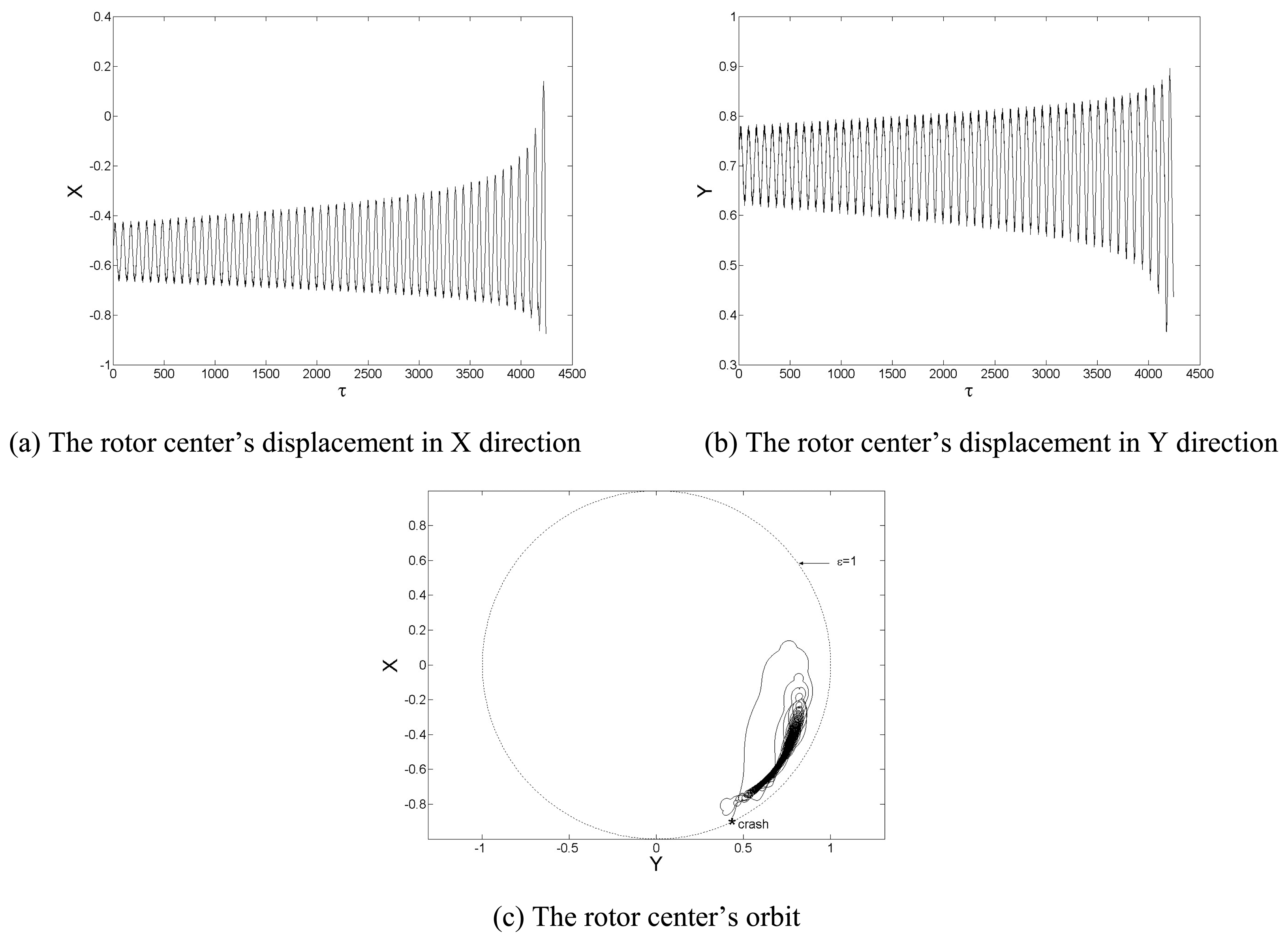
For a practical rotor, due to the fabrication defect, the mass center would inevitably depart from the geometry center, and the rotor is unbalanced. From the above discussion, it is known that the continuum flow assumption will lead to a mistaken result of the dynamic characteristics of the system. Thus, the second order slip flow is adopted for the dynamic analysis of the unbalanced micro rotor. For difference rotational speed, the dynamical responses of an unbalance motor are acquired, which are shown in
Fig.12 and
Fig.13.
For some unbalanced rotor, the oscillation amplitude will keep growing and the rotor will crash into the bushing (
Λ =6.0,
β=1%), as shown in
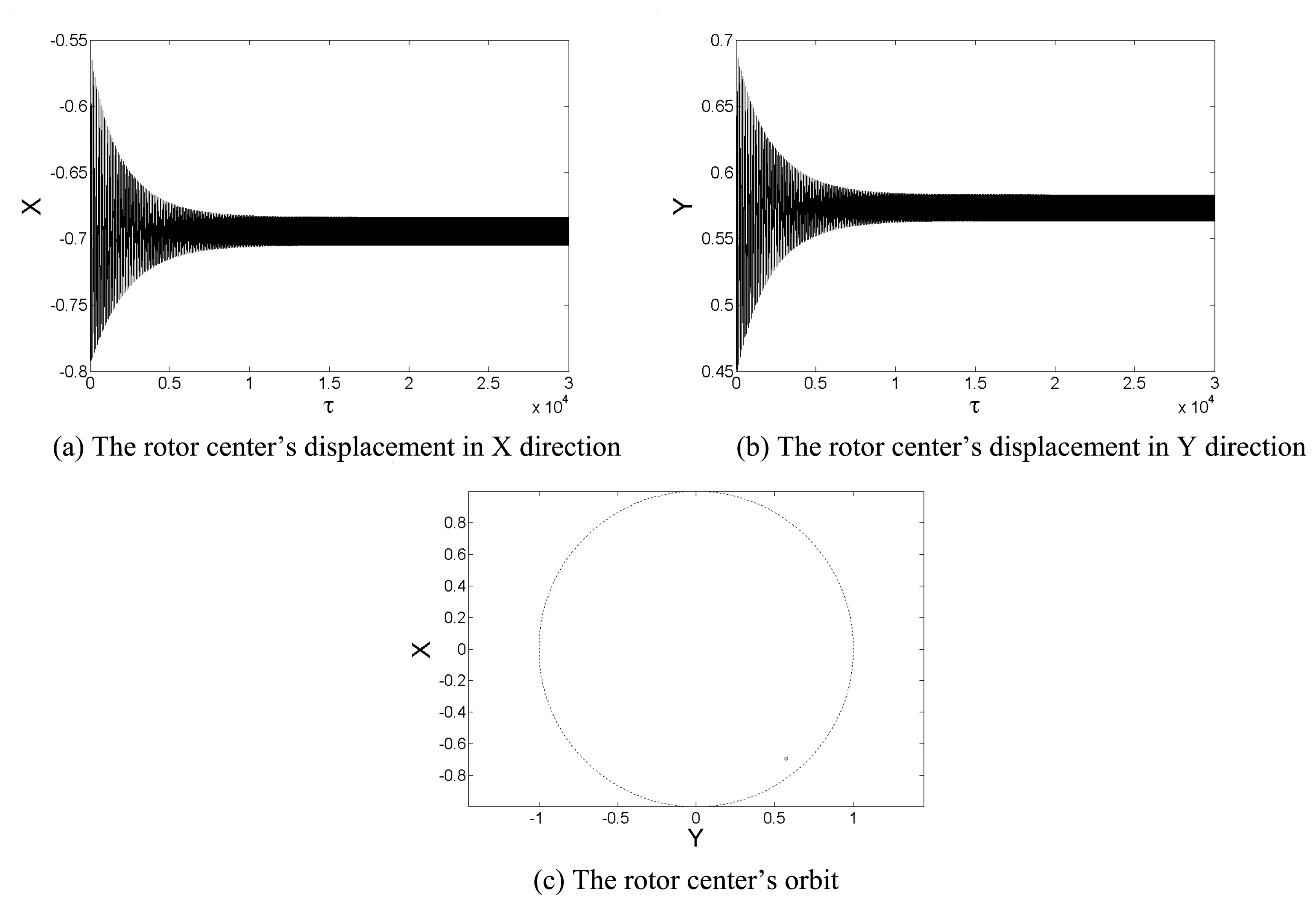
Fig.12. In other condition, the oscillation amplitude will decay to a certain value and the rotor motion become a whirl of small amplitude (
Λ =10,
β=1%), as shown in
Fig.13. Unlike balanced rotor, the unbalanced rotor will not converge to the static equilibrium position, for the unbalanced mass will be an excitation force due to the rotation of the rotor. For this reason, the whirl frequency is equal to the rotational rate as shown in
Fig.14.
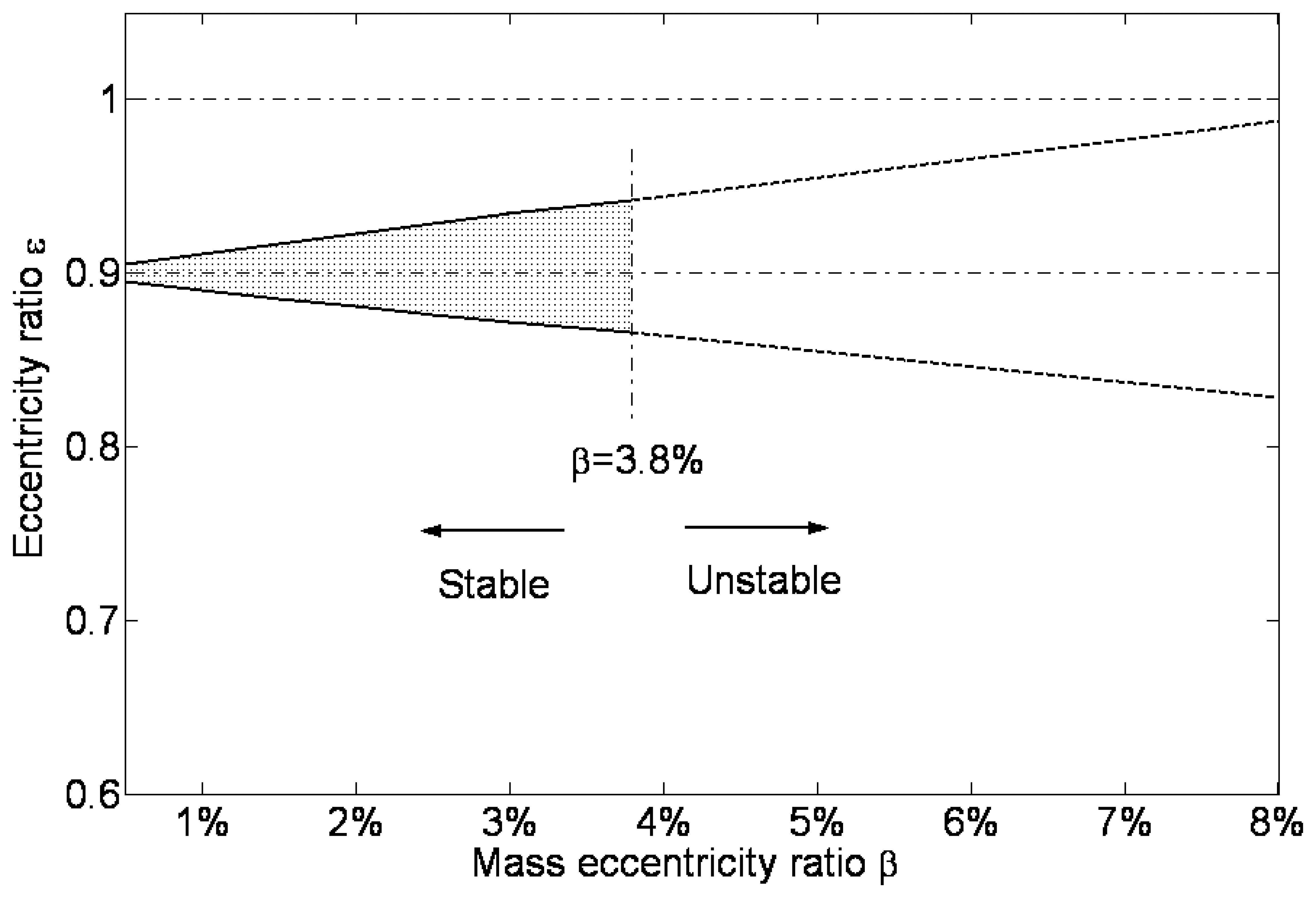
With the increase of the unbalance ratio, the whirl amplitude increases, as shown in
Fig.15. The two lines in the figure represent the maximum and minimum eccentricity ratio of the rotor in the whirling motion. It shows that, when the unbalance ratio increases, the whirl amplitude is enlarged. And it is almost a linear relation. Deduced from the increase trend, it is supposed that the maximum eccentricity ratio of the rotor will approach 1 when the unbalance ratio is about 10%, at which the rotor will crash into the bushing. But during the calculation, it is found that the rotor will crash into the bushing when the unbalance ratio is 3.8%, which is much less than 10%. Examining the dynamical response shown in
Fig.13, it is found that the whirl amplitude of the unsteady state oscillation is much lager than that of the steady state motion. Consequently, the maximum eccentricity ratio of the rotor at the unsteady state is much higher. As a result, the rotor will crash into the bushing before steady whirl state when the unbalance ratio is 3.8%.


