A Novel Bioinspired PVDF Micro/Nano Hair Receptor for a Robot Sensing System

Abstract
:1. Introduction
2. PVDF Hair Receptor Modeling
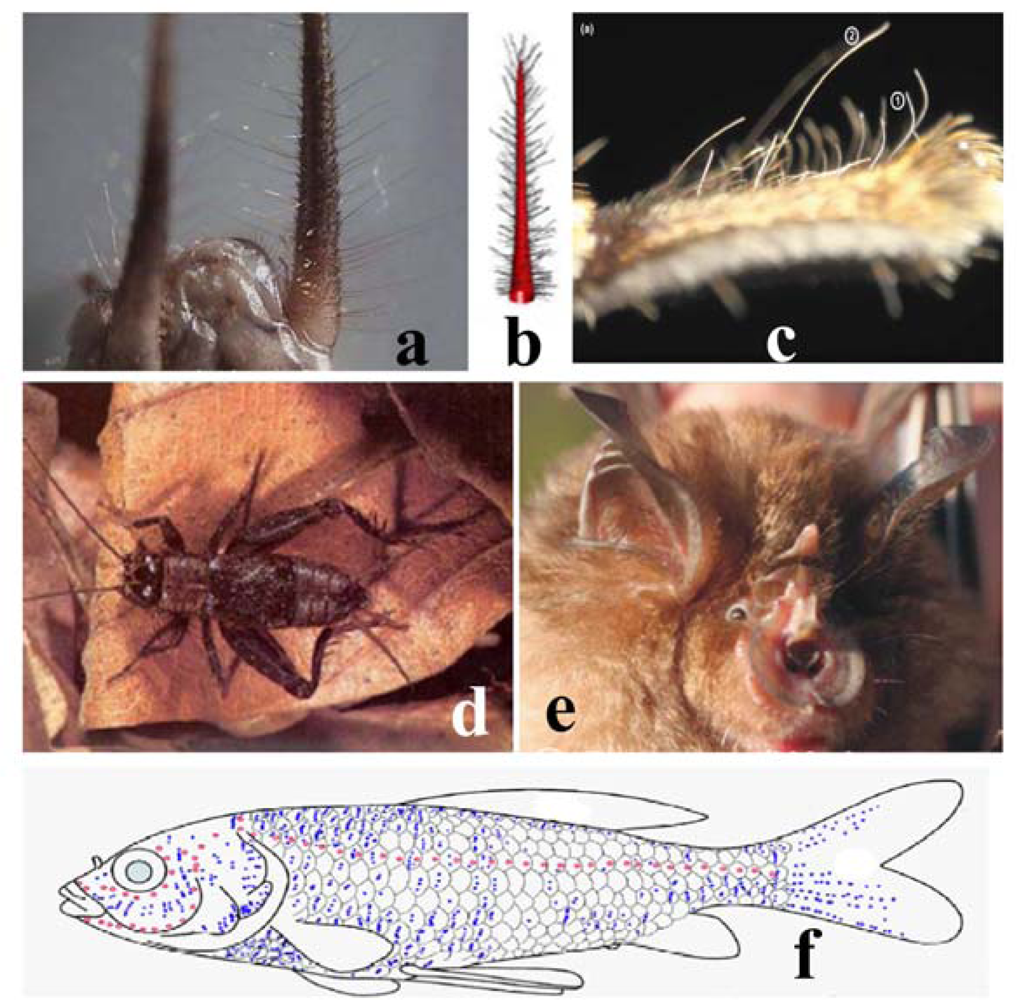
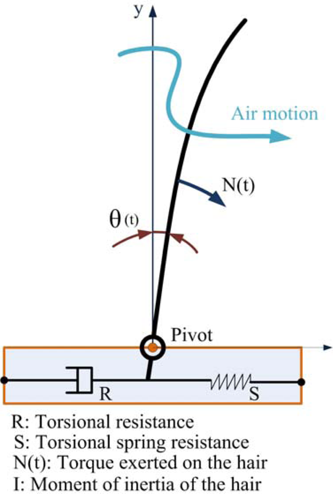
2.1. A biological Model of Hair Receptor
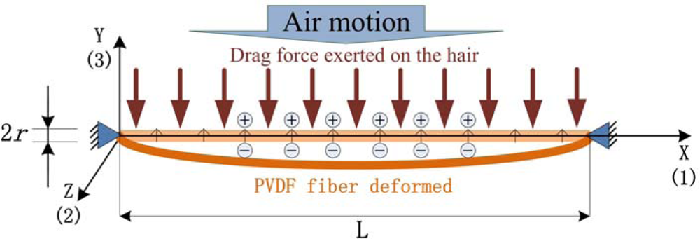
2.2. A Simplified Model for PVDF Artificial Hair Receptor
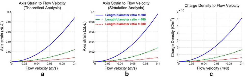
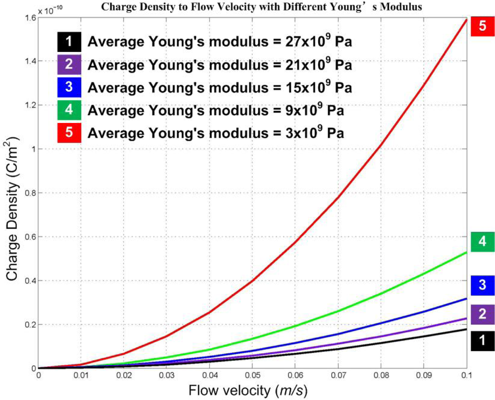
2.3. Scaling Down Analysis
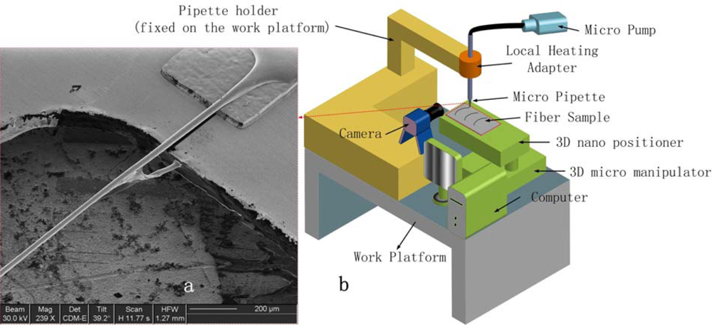
3. Aligned Micro/Nano Fibers Drawing Fabrication
3.1. Micro/Nano Fiber Fabrication Techniques
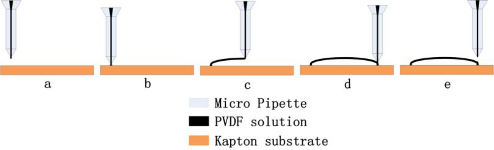
3.2. PVDF Micro/Nano Fiber Drawing
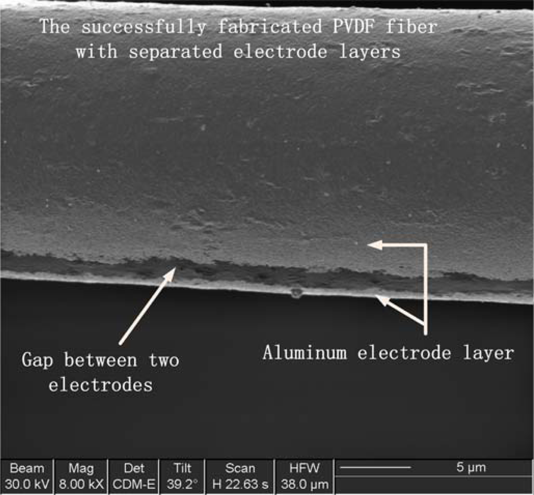
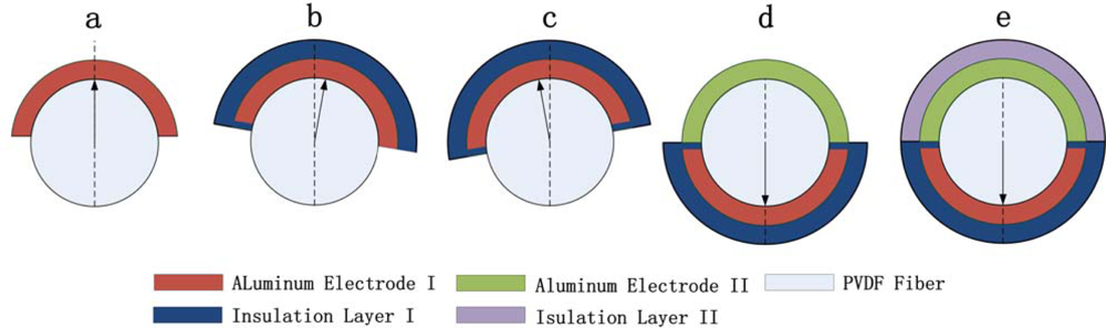
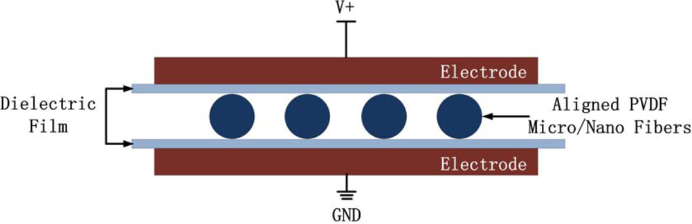
3.3. Post Process of Fiber Fabrication (Electrodes Deposition and Poling)
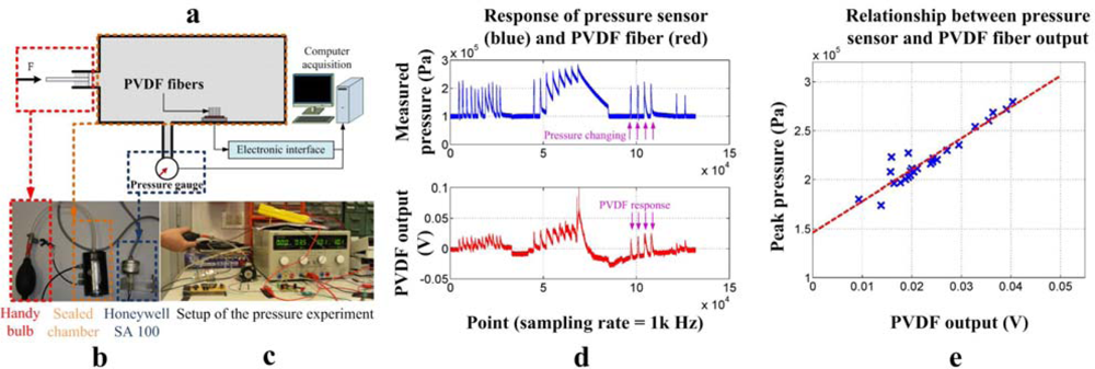
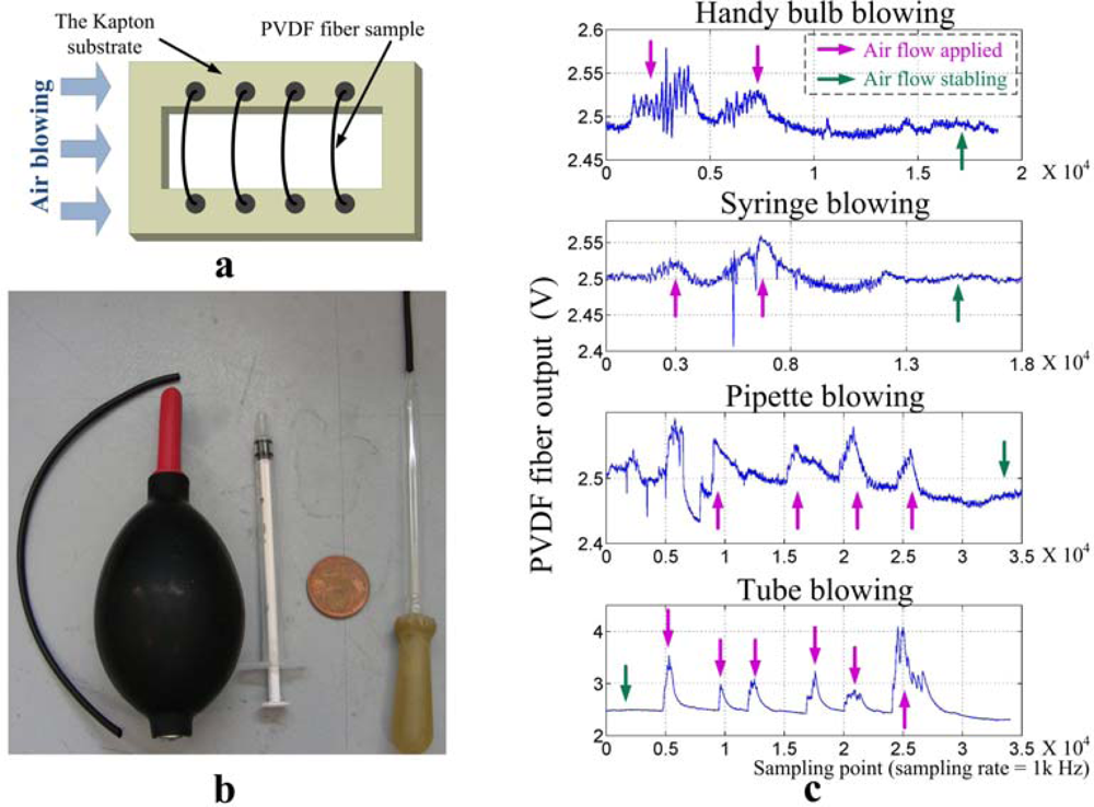
4. Validation Experiments
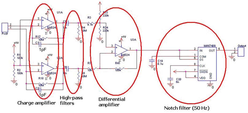
4.1. Electronic Interface for PVDF Micro/Nano Fibers
4.2. Validation Experiments for the Novel Artificial PVDF Fiber Sensor
5. Conclusions and Future Work
Acknowledgments
References and Notes
- Alexander, R.M. Principles of Animal Locomotion; Princeton University Press: Princeton, NJ, USA, 2003. [Google Scholar]
- Ogura, Y.; Kataoka, T.; Aikawa, H.; Shimomura, K.; Lim, H.; Takanishi, A. Evaluation of various walking patterns of biped humanoid robot. Proceedings of the IEEE International Conference on Robotics and Automation, Barcelona, Spain, April 2005; pp. 605–610.
- Plestan, F.; Grizzle, J.W.; Westervelt, E.R.; Abba, G. Stable walking of a 7-DOF biped robot. IEEE Trans. Robotic. Autom 2003, 19, 653–668. [Google Scholar]
- Scarfogliero, U.; Folgheraiter, M.; Gini, G. Advanced steps in biped robotics: innovative design and intuitive control through spring damper actuator. Proceedings of the IEEE Conference on Humanoids, Los Angeles, CA, USA, November 2004; pp. 196–214.
- Berns, K.; Ilg, W.; Deck, M.; Albiez, J.; Dillmann, R. Mechanical construction and computer architecture of the four-legged walking machine BISAM. IEEE/ASME Trans. Mechatron 1999, 4, 32–38. [Google Scholar]
- Nelson, G.; Blankespoor, K.; Raibert, M. Walking BigDog: insights and challenges from legged robotics. J. Biomech 2006, 39, S360. [Google Scholar]
- Nelson, G.M.; Quinn, R.D.; Bachmann, R.J.; Flannigan, W.C. Design and simulation of a cockroach-like hexapod robot. Proceedings of the IEEE International Conference on Robotics and Automation, New Mexico, NM, USA, April 1997; pp. 1106–1111.
- Saranli, U.; Buehler, M.; Koditschek, D.E. RHex: A simple and highly mobile hexapod robot. Int. J. Robot. Res 2001, 20, 616–631. [Google Scholar]
- Flannigan, W.C.; Nelson, G.M.; Quinn, R.D. Locomotion controller for a crab-like robot. Proceedings of the IEEE International Conference on Robotics and Automation, Leuven, Belgium, May 1998; pp. 152–156.
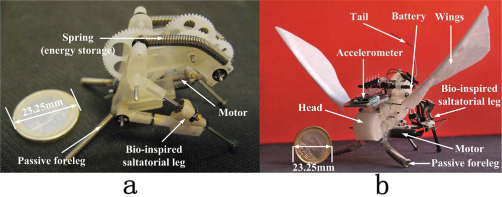
- Li, F.; Bonsignori, G.; Scarfogliero, U.; Chen, D.; Stefanini, C.; Liu, W.; Dario, P.; Fu, X. Jumping mini-robot with bio-inspired legs. Proceedings of IEEE International Conference on Robotics and Biomimetics, Bangkok, Thailand, February 2009; pp. 933–938.
- Netten, S.M.v. Hair Cell Mechano-transduction: its influence on the gross mechanical characteristics of a hair cell sense organ. Biophys. Chem 1997, 68, 43–52. [Google Scholar]
- Shimozawa, T.; Kumagai, T.; Baba, Y. Structural scaling and functional design of the cercal wind Receptor. J. Comp. Physiol. A 1998, 183, 171–186. [Google Scholar]
- Dangles, O.; Magal, C.; Pierr, D.; Olivier, A.; Casas, J. Variation in morphology and performance of predator-sensing systems in wild cricket populations. J. Exp. Biol 2004, 208, 461–468. [Google Scholar]
- Li, J.; Chen, J.; Liu, C. Micromachined biomimetic sensor using modular artificial hair cells. Proceedings of Nanospace Conference, Houston, TX, USA, January 2000.
- Dijkstra, M.; Baar, J.J.v.; Wiegerink, R.J.; Lammerink, T.S.J.; Boer, J.H.d.; Krijnen, G.J.M. Artificial sensory hairs based on the flow sensitive receptor hairs of crickets. J. Micromechanic. Microengineer 2005, 15, S132–S138. [Google Scholar]
- Levi, R.; Camhi, J.M. Wind direction coding in the cockroach escape response: Winner does not take all. J. Neurosci 2000, 20, 3814–3821. [Google Scholar]
- Dangles, O.; Casas, J.; Coolen, I. Textbook cricket goes to the field: the ecological scene of the neuroethological play. J. Exp. Biol 2006, 209, 393–398. [Google Scholar]
- Barth, F.G. Spider mechanoreceptors. Curr. Opin. Neurobiol 2004, 14, 415–422. [Google Scholar]
- Peremans, H.; Reijniers, J. The CIRCE head: a biomimetic sonar system. Proceedings of ICANN, Warsaw, Poland, September 2005; pp. 283–288.
- Goulet, J.; Engelmann, J.; Chagnaud, B.P.; Franosch, J.P.; Suttner, M.D.; Hemmen, J.L. Object localization through the lateral line system of fish theory and experiment. J. Comp. Physiol. A 2008, 194, 1–17. [Google Scholar]
- Fan, Z.; Chen, J.; Zou, J.; Bullen, D.; Liu, C.; Delcomyn, F. Design and fabrication of artificial lateral line flow sensors. J. Micromechanic. Microengineer 2002, 12, 655–661. [Google Scholar]
- Chen, N.; Chen, J.; Engel, J.; Pandya, S.; Tucker, C.; Liu, C. Development and characterization of high sensitivity bioinspired artificial haircell sensor. Proceedings of Solid-State Sensors, Actuators, and Microsystems Workshop, Hilton Head Island, SC, USA, June 2006.
- Engel, J.M.; Chen, J.; Bullen, D.; Liu, C. Polyurethane rubber as a MEMS material: characterization and demonstration of an all-polymer two-axis hair cell flow sensor. Proceedings of the IEEE International Conference on MEMS, Miami Beach, FL, USA, January 2005; pp. 279–282.
- Krijnen, G.J.M.; Dijkstra, M.; Baar, J.J.v.; Shankar, S.S.; Kuipers, W.J.; Boer, R.J.H.d.; Altpeter, D. MEMS based hair flow-sensors as model systems for acoustic perception studies. Nanotechnology 2006, 17, S84–S89. [Google Scholar]
- Ondarcuhu, T.; Joachim, C. Drawing a single nanofibre over hundreds of microns. Europhys. Lett 1998, 42, 215–220. [Google Scholar]
- Harfenist, S.; Cambron, S.; Nelson, S.; Berry, S.; Isham, A.; Crain, M.; Walsh, K.; Keynton, R.; Cohn, R. Direct drawing of suspended filamentary micro- and nanostructures from liquid polymers. Nano Lett 2004, 4, 1931–1937. [Google Scholar]
- Nain, A.S.; Wong, J.C.; Amon, C.; Sitti, M. Drawing suspended polymer micro-/nanofibers using glass micropipettes. Appl. Phys. Lett 2006, 89, 183105. [Google Scholar]
- Nain, A.; Amon, C.; Sitti, M. Proximal probes based nanorobotic drawing of polymer micro/nanofibers. IEEE Trans. Nanotechnol 2006, 5, 499–510. [Google Scholar]
- Martin, C. Nanomaterials: A membrane-based synthetic approach. Science 1994, 266, 1961–1966. [Google Scholar]
- Ma, P.X.; Zhang, R. Synthetic nano-scale fibrous extracellular matrix. J. Biomed. Mater. Res 1999, 46, 61–72. [Google Scholar]
- Whitesides, G.M.; Grzybowski, B. Self-Assembly at All Scales. Science 2002, 295, 2418–2421. [Google Scholar]
- Choi, S.W.; Kim, J.R.; Ahn, Y.R.; Jo, S.M.; Cairns, E.J. Characterization of electrospun PVDF fiber-based polymer electrolytes. Chem. Mater 2007, 19, 104–115. [Google Scholar]
- Seoul, C.; Kim, Y.T.; Baek, C.K. Electrospinning of poly (vinylidene fluoride)/dimethylformamide solutions with carbon nanotubes. J. Polym. Sci., Part B: Polym. Phys 2003, 41, 1572–1577. [Google Scholar]
- Ohzawa, Y.; Nagano, Y.; Matsuo, T. Studies on dry spinning I. fundamental equations. J. Appl. Polym. Sci 1969, 13, 257–283. [Google Scholar]
- Liu, W.; Stefanini, C.; Sumer, B.; Li, F.; Chen, D; Menciassi, A.; Dario, P.; Sitti, M. A novel artificial hair receptor based on aligned PVDF micro/nano fibers. Proceedings of IEEE International Conference on Robotics and Biomimetics, Bangkok, Thailand, February 2009; pp. 49–54.
- Hunt, T.P.; Westervelt, R.M. Dielectrophoresis tweezers for single cell manipulation. Biomed. Microdevices 2006, 8, 227–230. [Google Scholar]
- Wu, Y.; Zhou, D.; Spinks, G.M.; Innis, P.C.; Megill, W.M.; Wallace1, G.G. TITAN: a conducting polymer based microfluidic pump. Smart Mater. Struct 2005, 14, 1511–1516. [Google Scholar]
- Furukawa, T. Piezoelectricity and pyroelectricity in polymers. IEEE Trans. Electr. Insul 1989, 24, 375–394. [Google Scholar]
- Shen, Y.; Xi, N.; Li, W.J. Contact and force control in microassembly. Proceedings of IEEE International Symposium on Assembly and Task Planning, Besanpon, France, July 2003.
- Liu, W.; Menciassi, A.; Scapellato, S.; Dario, P.; Chen, Y. A biomimetic sensor for a crawling minirobot. Rob. Auton. Syst 2006, 54, 513–528. [Google Scholar]
- Chen, N.; Tucker, C.; Engel, J.M.; Yang, Y.; Pandya, S.; Liu, C. Design and characterization of artificial haircell sensor for flow sensing with Ultrahigh Velocity and Angular Sensitivity. J. Microelectromech. Syst 2007, 16, 999–1014. [Google Scholar]


©2010 by the authors; licensee Molecular Diversity Preservation International, Basel, Switzerland. This article is an open access article distributed under the terms and conditions of the Creative Commons Attribution license (http://creativecommons.org/licenses/by/3.0/)
Share and Cite
Li, F.; Liu, W.; Stefanini, C.; Fu, X.; Dario, P. A Novel Bioinspired PVDF Micro/Nano Hair Receptor for a Robot Sensing System. Sensors 2010, 10, 994-1011. https://doi.org/10.3390/s100100994
Li F, Liu W, Stefanini C, Fu X, Dario P. A Novel Bioinspired PVDF Micro/Nano Hair Receptor for a Robot Sensing System. Sensors. 2010; 10(1):994-1011. https://doi.org/10.3390/s100100994
Chicago/Turabian StyleLi, Fei, Weiting Liu, Cesare Stefanini, Xin Fu, and Paolo Dario. 2010. "A Novel Bioinspired PVDF Micro/Nano Hair Receptor for a Robot Sensing System" Sensors 10, no. 1: 994-1011. https://doi.org/10.3390/s100100994