3.1.1. Selection of Porous Support
For the preparation of very thin and pinhole-free supported membranes the choice of the porous substrate is crucial. Different support configurations and materials are commercially available, however, asymmetric tubular supports are preferred because of their larger surface/volume ratio compared with disk shape substrates. The characteristics of the support determine the required selective layer thickness in order to obtain a defect-free thin layer. Both ceramic and metallic supports have been extensively used. On the one hand, ceramic supports are very interesting because of their suitable surface properties and chemical compatibility with Pd layers. However, their integration in a membrane reactor is more complex and they are mechanically weaker than metallic supports. On the other hand, the thermal expansion of ceramic supports is smaller than metallic supports and is closer to the thermal expansion of Pd and its alloys. The thermal expansion coefficients of some materials used for the preparation of composite membranes have been listed in
Table 4. The most widely used support is alumina, which has smaller thermal expansion coefficient than Pd, which could cause failures in the membranes when used at higher temperatures. This problem can be reduced by using ZrO
2 or YSZ (yttria stabilized zirconia), which both have a thermal expansion coefficient closer to that of Pd.
The most important characteristics of porous supports for the deposition of very thin pinhole-free selective layers are: (a) small pore size; (b) smooth surface (c) thermal and chemical stability.
Supports with a small pore size are required for thin membranes without defects. Thus, the pore size of the support determines the minimum amount of material required to completely cover them and form a continuous surface. Mardilovich et al. [
108] have proven that the thickness required to obtain a dense layer is three times the diameter of the largest pore in the support. The minimum thickness of palladium required to deposit a dense layer on top of a porous support with different pore sizes was found to be much larger, as reported by Uemiya [
109] (see
Table 5).
Another property of the porous supports influences the required layer thickness: the surface roughness. High surface quality (small roughness) and controlled porosity can be obtained in ceramic supports. High surface quality (small roughness and pore size) can also be obtained by depositing a meso-porous layer onto porous supports [
110,
111,
112], which could however reduce the hydrogen permeation because of the induced mass transfer resistance of the additional layer. Additionally, the adhesion between the Pd layer and the additional meso-porous layer could be a problem, which would result in weak Pd membrane. McCool and co-workers [
110] improved the surface quality of commercial α-Al
2O
3 by deposition of a 5 µm thick γ-Al
2O
3 layer using a slip-casting technique of boehmite. The initial average pore size of the porous support was reduced from 200 nm to 4 nm, with a final porosity around 40%. Very thin PdAg layers (163–525 nm) with different silver content were deposited by DC sputtering. The best permeation results were obtained for a 117 nm thick Pd
82.6Ag
17.6 layer, for which the measured H
2/He selectivity and H
2 permeance at 300 °C were ~3800 and 7.69 × 10
−8 mol∙m
−2∙s
−1∙Pa
−1, respectively [
110]. Thoen et al. [
112] used commercial asymmetric α-Al
2O
3 tubes coated with ZrO
2 from Pall Corporation with a pore size of 20 nm. A 1.3 µm thick Pd
95Cu
5 layer was deposited by sequential electroless plating without the presence of EDTA as complexing agent. The permeated hydrogen flux at 365 °C with a feed pressure of ~435 kPa (~63 psig) was 1.5 mol∙m
−2∙s
−1. Checchetto et al. [
113] deposited a SiO
2 nanolayer (100 nm) on top of an Al
2O
3 porous disk with nominal pore size of 200 nm followed by deposition of 150 nm of PdAg by pulsed laser deposition, which was not completely defect free since the selectivity observed at 300 °C was around 600–900 at a pressure difference of 1 bar with a permeance of 1.4 × 10
−6 mol∙m
−2∙s
−1∙Pa
−1. Pan et al. [
114] modified α-Al
2O
3 hollow fibres with an initial pore size of 200 nm with 1 µm thick γ-Al
2O
3 by dip-coating and finally 2–3 µm of Pd were coated by ELP with a final selectivity exceeding 1000 at 400 °C and a permeance of 1.1 × 10
−6 mol∙m
−2∙s
−1∙Pa
−1, which is one order of magnitude smaller than the original support (2.1–2.5 × 10
−5 mol∙m
−2∙s
−1∙Pa
−1). Wu et al. [
115] and Li et al. [
116] modified α-Al
2O
3 (0.1 µm pore size) and Al
2O
3-ZrO
2 (0.2 µm pore size) supports, respectively, with TiO
2 followed by photo-catalytic deposition of Pd thin layers of 100 nm and 400 nm, respectively. The observed permeance and selectivity are presented in
Table 6, which can be compared with other layers deposited onto modified Al
2O
3, and ZrO
2 supports.
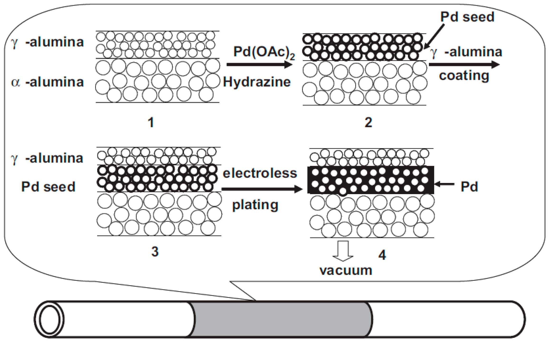
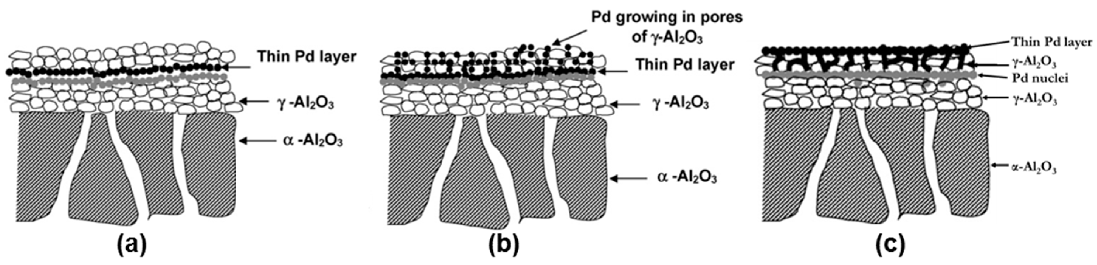
Pacheco Tanaka et al. [
111] modified tubular α-Al
2O
3 substrates with an average pore size of 150 nm by deposition of a meso-porous γ-Al
2O
3 layer by vacuum assisted dip-coating followed by a slow drying process at 40 °C and final calcination at 550 °C. These porous supports were also modified with YSZ/γ-Al
2O
3 mixtures, which were calcined at different temperatures (500–1000 °C) [
111]. The nitrogen permeance of the supports calcined at 1000 °C was close to twice the permeance of those calcined at 600 °C. During the calcination the pore radius decreased, causing larger pore size distributions at higher temperatures (2–9 nm) and a smaller distribution and size at 600 °C (1–4 nm). Both modified supports [
111,
117] were used for the preparation of pore-filled type membranes (which will be discussed in more detail in the
Section 3.5.2.
In addition to the pore size (distribution) and surface roughness, the stability of the support material under reductive environments at high temperatures and possible interactions with the material of the selective layer (in particular Pd) are two very important aspects to be considered in the preparation of supported membranes. Thermal stability of alumina supports in the presence of hydrogen at different temperatures was evaluated by Okazaki et al. [
118]. The authors found that alumina interacts with hydrogen at temperatures above 650 °C producing aluminium. This diffuses through the Pd layer forming an alloy at the interface as revealed by EDX analysis. In their experiments the hydrogen flux was diminished by a factor two after 50 h. This phenomenon proceeds even faster at higher temperatures, as the hydrogen permeation was totally suppressed after 2–3 h at 850 °C.
Paglieri et al. [
119] observed a similar decrease in the permeated hydrogen flux at 750 °C, where Pd was deposited onto alumina porous supports, with a complete and irreversible flux decay that could not be recovered even after thermal treatment in air or hydrogen in order to restore the hydrogen permeation.
Huang et al. [
120] detected diffusion between Pd and TiO
2 used as interdiffusion barrier. In membranes used for 23 days at 600 °C in the presence of pure hydrogen the authors found diffusion of components of the support (and interdiffusion barrier layer) at a depth of 2–3 µm along the interface. Diffusion was not observed when using ZrO
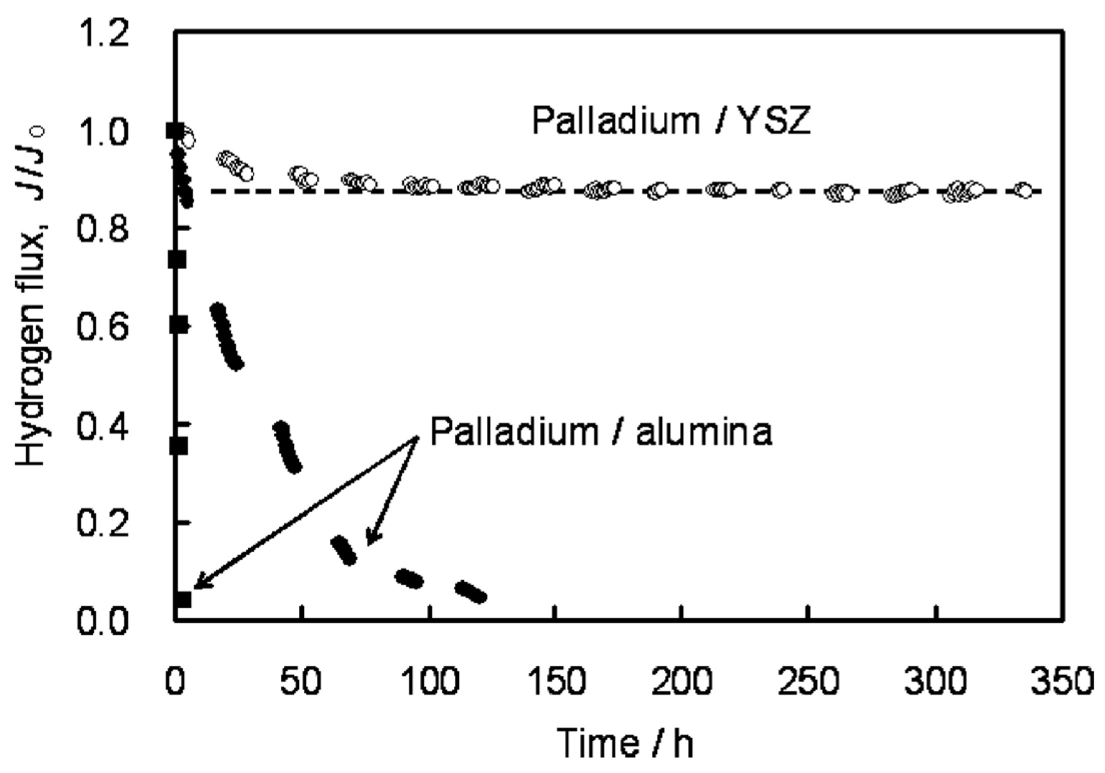
2 and YSZ interdiffusion barriers. Stability under reductive and oxidative atmospheres is obtained with cubic phase YSZ. Okazaki et al. [
121] found that YSZ represents the best choice for high temperature environments, such as for membrane assisted reactors for autothermal reforming. The authors tested a Pd/YSZ membrane during 336 h at 650 °C in pure hydrogen observing 10% reduction in the hydrogen flux during the first 50 h, as shown in
Figure 6. After this period, the hydrogen flux reached a
plateau without presence of nitrogen leaks. The tested membrane was analysed by cross-section SEM images and it was found that the selective layer did not show presence of Y and/or Zr. However, when using Pd/Al
2O
3 composite membranes, the hydrogen permeation flux was completely lost after ~125 h.
As far as metal supports are concerned, most of the papers published in the last few years have used porous supports made of stainless steel, followed by nickel substrates for higher temperatures. Metallic supports employed in the most recent studies have been summarized in
Table 7 including some characteristic parameters of the supports and techniques used for the deposition of the ceramic barriers. Stainless steel porous supports with different pore sizes from Mott Metallurgical Corporation are commonly used, where smaller pore size are preferred due to their smoother surface [
54,
122,
123,
124,
125]. Commercially available PSS supports are made of stainless steel 316L with different pore size, also called media grade. Typical media grades used are 0.1 µm and 0.2 µm, corresponding to an average pore size of 2–5 µm and 10 µm, respectively (measured by mercury intrusion). Larger media grades, 0.5 µm, are less used due to their larger average pore size (10–20 µm) which requires thicker Pd or interdiffusion barriers to reach complete surface coverage. Porous stainless steel substrates from Pall corporation were used with a pore size of 2 µm [
126], while YSZ modified PSS from Pall have also been used for membrane preparation [
127,
128,
129]. Some research groups prepared in-house metallic porous supports. A PSS tubular support was prepared by Straczewski using powder from GKN Sinter Metals [
130]. On the other hand, nickel porous support were prepared by sintering commercial nickel powder supplied by Vale Inco Pacific Ltd., Hong Kong (SAR), China [
106,
131]. For high temperature applications (>550 °C), Hastelloy X (Ni-based) from Mott Corporation is another option [
62,
132]. Except for the ZrO
2 modified PSS from Pall, all other metallic supports require an interdiffusion barrier, as discussed in the following section.
Mechanical failure of supported thin films due to the difference in thermal expansion coefficients between the selective layer and the porous supports can be avoided by deposition of an interdiffusion barrier with a similar expansion coefficient of the dense selective layer. Another possibility was reported by Zhao et al. [
133], who prepared a membrane with a modified electroless plating bath mixing a solution containing Pd (II) with a γ-Al
2O
3 (boehmite) sol. The porous substrate was coated with this solution in the presence of small amounts of polyvinyl alcohol (PVA) and polyethyleneglycol (PEG). Before calcination at 600 °C, the coated layer was dried during two days at low temperature (5 °C) and 65% relative humidity. Before electroless plating, the membrane was exposed to hydrogen at 500 °C to reduce the palladium. Finally, a 1 μm thick Pd layer was deposited by ELP as the support was activated. The permeated hydrogen flux of the supported membrane was 0.108 mol∙m
−2∙s
−1 at 450 °C, but the corresponding ideal H
2/N
2 selectivity was very low: 20.
The development of a thin membrane with high permeation and selectivity is therefore not always possible due to the factors discussed before such as support pore size, roughness, etc. In many of the studies presented in this period either a high flux or a high selectivity was achieved. However, Bredesen and co-workers (SINTEF) reported the preparation of Pd-Ag membranes with both very high permeation and selectivity [
126]. A 2.8 μm thick Pd
77Ag
23 layer was deposited by magnetron sputtering onto a silicon wafer, which was removed and rolled onto a 316L stainless steel tubular porous support. The measured hydrogen flux at 400 °C and 26 bar of feed pressure was 8.64 mol∙m
−2∙s
−1 with a H
2/N
2 selectivity of 1600. These results were even improved after thermal treatment in air at 400 °C for three days. The hydrogen flux and selectivity measured under the same conditions reported before thermal treatment in air were 18.43 mol∙m
−2∙s
−1 and 2900, respectively. The initial hydrogen permeance, 6.48 × 10
−3 mol∙m
−2∙s
−1∙Pa
−0.5, was enhanced one order of magnitude after thermal treatment in air with a measured permeance of 1.46 × 10
−2 mol∙m
−2∙s
−1∙Pa
−0.5. A long-term test was performed at temperatures below 375 °C during 85 days in the presence of a 50% H
2/50% N
2 feed gas revealing great stability for the first 40 days. However, the nitrogen flux increased from 4.46 × 10
−3 to 6.32 × 10
−3 mol∙m
−2∙s
−1 at 10 bar feed pressure, while the hydrogen flux was maintained at around 8.78 mol∙m
−2∙s
−1. The corresponding H
2/N
2 ideal selectivity was 1400. Pinholes of about 0.1–0.3 μm in diameter were observed by SEM on the membrane surface exposed to hydrogen after long-term experiments. The membranes prepared by SINTEF were tested under WGS environment at 400 °C and 26 bar feed pressure [
134]. In the presence of a gas mixture containing 57.5% H
2, 18.7% CO
2, 18.7% H
2O, 3.8% CO and 1% CH
4, the measured hydrogen permeance was 1.1 × 10
−3 mol∙m
−2∙s
−1∙Pa
−0.5. These membranes exhibited at least one year stability under WGS conditions and mixtures of H
2-N
2 at feed pressure of 10 bar.
A short air treatment allows activation (or perhaps cleaning) of the membrane and increases the flux of H
2. It was suggested by Roa and Way [
135] that exposure to air resulted in surface cleaning and enhancement in the surface area for “as prepared” (not totally clean) membranes. This effect depends on the exposition time and temperature. However, this effect is not representative for all Pd-alloyed membranes as Zhang et al. [
136] reported in their study where Pd
75Ag
25 and Pd
90Au
10 membranes were “activated” under air treatment at 300 °C. The measured hydrogen flux before and after air treatment for the PdAu layer were practically the same, while the authors observed an increase in the flux for the PdAg membrane ranging between ~80% at a transmembrane pressure difference of 55 Pa
0.5, and ~50% at a pressure difference of 180 Pa
0.5.
3.1.2. Selection of Interdiffusion Layer
The undesired diffusion of components from the porous stainless steel support such as Fe, Cr and Ni to the Pd selective layer at high temperatures is a well-known phenomenon. After diffusion, an alloy with Pd is formed that decreases the hydrogen permeance of the membrane due to the reduction of the solubility and diffusivity of hydrogen into the Pd-alloy lattice; Pd and Fe from the support start forming a solid solution at 500 °C in the presence of hydrogen after 20 h [
137]. The amount of iron in the Pd layer interface increases from 2 wt. % to 59 wt. % upon a thermal treatment with a temperature increase from 500 °C to 800 °C. In contrast, silver does not form a solid solution with iron at these temperatures.
In order to avoid the diffusion of elements between the metallic support and the dense selective layer during operation at high temperatures, the deposition of a ceramic barrier is performed on top of the metallic porous support. Moreover, metallic supports having an adequate pore size and roughness for thin Pd membranes are difficult to fabricate. Therefore, the deposition of the ceramic layer also improves the surface quality of the original support allowing the deposition of thinner selective layers.
The selection of the ceramic material for the interdiffusion barrier layer is a critical point to take into account, since an asymmetric membrane composed of materials with different thermal expansion coefficients could result in a total failure of the membrane during operation especially at high temperatures. Ceramics used as inter-diffusion barrier need to have as similar thermal expansion coefficient as the selective metallic layer and support. The most common barrier material, alumina [
123,
138,
139,
140], has a low thermal expansion coefficient compared with ZrO
2 [
108,
120,
141,
142,
143,
144] or YSZ (yttria stabilized zirconia) [
120,
125,
128,
130,
145], which both have larger thermal expansion coefficients and closer to Pd and its alloys (see
Table 4). Other ceramic layers used as barrier are TiO
2 [
120,
130] or CeO
2 [
106,
146] which both possess a large thermal expansion coefficient and close to the thermal expansion coefficient of Pd. Oxidation of porous stainless steel supports provide a chromium oxide (Cr
2O
3) layer, which can act as an interdiffusion barrier. The thickness of the Cr
2O
3 layer is controlled by the oxidation temperature and time [
145,
147] or by the electrodeposition of Cr followed by oxidation treatment in air [
147]. Nickel porous supports are generally modified by the deposition of thin ceramic layers of Al
2O
3, ZrO
2 and CeO
2. By physical vapour deposition, 0.2 µm thick alumina and zirconia layers were deposited [
131], while CeO
2 (0.5 µm) was obtained by dip-coating after modification of the Ni-support by wetness impregnation with alumina [
106].
The composite membranes based on metallic porous supports modified with interdiffusion barriers have been summarized in
Table 8.
The large pore size of commercial PSS supports can be reduced before deposition of ceramic layers by a pre-treatment based on polishing and then etching with an acid solution (HNO
3 and HCl) as Li et al. suggested [
139]. The initial roughness of PSS supports with media grade of 0.2 μm was reduced from 20 μm to 5 μm by polishing. However, most of the pores were completely closed, decreasing more than 99% the initial H
2 permeation rate. Acid etching of the polished surface removed more than 15 μm of material, opening pores and, as a result, the permeance of the support was enhanced 15% more than with the initial support without polishing. The remaining roughness was reduced by deposition of a 2 μm thick alumina layer using particles of around 2.5 μm. The surface roughness was decreased from 5 μm to 2 μm after deposition of the first layer, which did not cover the metallic substrate completely and the permeation rate was reduced by 40%. Subsequently, the metallic support was completely covered by deposition of a second layer (~1 µm) with a particle size of 0.3 μm. The measured separation factor H
2/N
2 was less than 3.74 (Knudsen diffusion), suggesting still a contribution of viscous flow. A defect-free Pd layer (5 μm) was deposited by ELP [
139] exhibiting a permeance of 3.39 × 10
−3 mol∙m
−2∙s
−2∙Pa
−0.5 at 550 °C and a pressure difference of 340 kPa.
A similar method for the deposition of alumina was reported by Chi et al. [
140] without pre-treatment for supports with the same characteristics as used by Li et al. [
139]. The particle sizes of the deposited layers were about 10 µm and 1 µm. The authors did not report the thickness of the layers, but suggested that the first layer blocked the large pores of the metallic support, while the second layer covered the surface completely [
140]. The measured helium flux was reduced 7.36% and 21.3% after deposition of the two layers, respectively. The deposited dense Pd-layer by ELP onto the original support and the modified support with two layers was reduced from 31.5 µm to 4.4 µm. The permeance of the thinner membrane at 500 °C and a pressure difference of 800 kPa was 2.94 × 10
−3 mol∙m
−2∙s
−1∙Pa
−0.5, with an ideal selectivity H
2/He of 1124. Additionally, the hydrogen flux through unmodified PSS with a 31.5 µm thick Pd layer was decreasing during the experiment due to diffusion of metal elements from the support to the Pd layer.
Broglia et al. [
138] reduced the original roughness of PSS with a nominal pore size of 0.l μm with γ-Al
2O
3 by dip coating followed by the deposition of a second layer obtained by hydrolysis of metal-organic alumina. They found that the mesoporous alumina (3–4 μm) layer covered the support completely. However, part of this ceramic layer was dissolved by the Pd-activation solution due to the acidity of the solution. A pinhole-free 11 μm thick Pd layer was deposited by ELP with total coverage of the modified support. Unfortunately, the authors did not report permeation experiments.
Tong et al. introduced a cerium hydroxide solution into a Mott PSS tubular support (particle retention size of 0.2 µm) applying vacuum in the inner side of tube [
146]. Two layers of 6 µm and 10 µm of Pd were deposited by ELP, resulting in a H
2/Ar selectivity of 108 for the thicker layer, while the separation factor of the 6 µm layer was lower (only 14). The defects of this last membrane were repaired by chemical vapor deposition sublimating Pd (II) hexafluoroacetylacetonate. After 3 CVD treatments the overall thickness of Pd was around 6.4 µm and the selectivity was improved to 565 with a hydrogen permeation flux of 0.235 mol∙m
−2∙s
−1 at 500 °C and a pressure difference of 100 kPa.
Straczewski deposited YSZ and TiO
2 onto an in-house PSS substrate produced using powder from GKN Sinter Metals [
130]. A smoother surface was obtained before deposition of the interdiffusion layer by wet powder spraying of fine particles, followed by deposition of <100 µm thick YSZ layer by atmospheric plasma spraying (APS) or thinner (<15 µm thick) TiO
2 by wet powder spraying (WPS). The thinner TiO
2 layers presented a larger surface quality (small pore size, large porosity and smooth surface) than the YSZ layers. Furthermore, the measured nitrogen permeance for the TiO
2 layers was ~1.8 × 10
−5 mol∙m
−2∙s
−1∙Pa
−1, one order of magnitude higher than for the thicker YSZ layer, ~3.2 × 10
−6 mol∙m
−2∙s
−1∙Pa
−1. No significant changes were observed on the permeated N
2 flux through the YSZ layer after nine thermal-cycling tests at 700 °C with different heating rates. On the other hand, the N
2 flux was reduced every cycle for TiO
2 till 10% of the initial N
2 flux. Thicker Pd layers were required and were deposited onto YSZ (24.8–30 μm) than on TiO
2 (8.3–14.9 μm) due to the better surface quality of last one. A slight increase in the N
2 flux was measured for the Pd-YSZ-PSS composite after a thermal treatment at 700 °C. Meanwhile, the N
2 flux decreased for the Pd-TiO
2 system when the heating rate was increased, suggesting sintering of the particles of the intermediate layer. The properties of the intermediate and selective layers are reflected in the hydrogen permeation flux. The thicker Pd(25.3 μm)-YSZ-PSS membranes permeated 0.14 mol∙m
−2∙s
−1 of H
2 at 600 °C and a transmembrane pressure of 2 bar, in terms of permeance (5.7 × 10
−4 mol∙m
−2∙s
−1∙Pa
−0.5) one order of magnitude smaller than for the Pd(14.3 μm)-TiO
2-PSS composite (2.6 × 10
−3 mol∙m
−2∙s
−1∙Pa
−0.5). The calculated ideal H
2/N
2 selectivity was similar and close to 200 for both membranes [
130].
Huang et al. [
120] compared three different ceramic barriers (ZrO
2, YSZ and TiO
2) deposited onto 310L porous supports by different deposition techniques. Very thin (2 µm) ZrO
2 layers were obtained by magnetron sputtering resulting in incomplete coverage of the porous support, which resulted in intermetallic diffusion at points where the Pd-layer was in contact with stainless steel. Thicker (10–70 µm) and rougher YSZ layers were obtained by APS, where the largest pore size (1.9 µm) of the original support was reduced to 0.78 µm. However, the nitrogen flux was reduced to 15% of the flux through the original support. In contrast, the nitrogen flux of the deposited TiO
2 by WPS with a large thickness (40–60 µm) was still 77% of the initial value having a smaller pore diameter (0.22 µm). Nevertheless, adherence of the TiO
2 layer was compromised at higher temperatures. The required thicknesses of Pd to obtain complete coverage via ELP were 9 µm, 14 µm and 23 µm for TiO
2, ZrO
2 and YSZ, respectively. Permeance values of the composite membranes at 500 °C and a pressure difference of 0.5 bar are reported in
Table 8, where the best results were obtained for a Pd/TiO
2/PSS with 1.91 × 10
−3 mol∙m
−2∙s
−1∙Pa
−0.5 with an ideal H
2/N
2 selectivity of ~800. Other composites showed a lower permeance related to the thicker Pd layers, however, the selectivity of both was around ~200 Tardini et al. [
123] compared the effect of ZrO
2 and Al
2O
3 as an interdiffusion barrier layer on top of PSS, requiring at least a 10 μm thick selective layer (Pd
92Au
8) for ZrO
2 modified porous stainless steel support, while a double thickness was required to deposit a defect-free membrane on top of an Al
2O
3 modified porous support. Moreover, 4%–5% Fe was detected in the PdAu layer deposited on top of an Al
2O
3 modified composite due to interdiffusion of elements from the metallic support, because the ceramic layer was too thin and did not cover the metallic support adequately. In terms of permeation rates, the Korea Institute of Energy Research (KIER) reported that ZrO
2 deposited by sputtering was preferred as interdiffusion barrier layer on top of porous nickel supports (PNS), since the measured nitrogen flux was 1.5 times higher when compared with Al
2O
3 interdiffusion barrier layers. Larger pore sizes were observed by SEM on the ZrO
2 supported surface [
131]. Chotirach and co-workers [
142] reported that a 0.5 μm thick ZrO
2 (used as a barrier) deposited by DC magnetron sputtering and oxidized in air, reduced the diffusion of elements from the support to the selective layer. The same authors also deposited ZrN, however larger hydrogen permeation rates were obtained with ZrO
2.
Wang et al. [
143] used a colloidal zirconium oxide (colloid size around 3 media grade at a pH 7.6) solution into PSS with media grade of 0.2 μm. The deposition was repeated five times until a constant separation factor between He/Ar was obtained. A pinhole-free Pd layer of 10 μm was deposited by ELP exhibiting 6.86 × 10
−4 mol∙m
−2∙s
−1∙Pa
−0.5 as permeance at 550 °C and a pressure difference of 100 kPa. Argon was detected during the heating process indicating the formation of defects.
Gao and co-workers [
144] deposited Pd-doped zirconia sol by dip coating onto PSS substrates (0.2 μm media grade) followed by co-deposition of pinhole-free Pd
84Cu
15 layers of 5 μm by electroless plating. The thicknesses of the ZrO2 layers were not reported. Homogeneity of the selective layer was confirmed by XPS analysis after a thermal treatment at 480 °C in H
2 for 5 h. The measured hydrogen flux at 480 °C and a pressure difference between the retentate and permeated side of 250 kPa was 0.6 mol∙m
−2∙s
−1 corresponding to a permeance of 2.19 × 10
−3 mol∙m
−2∙s
−1∙Pa
−0.5.
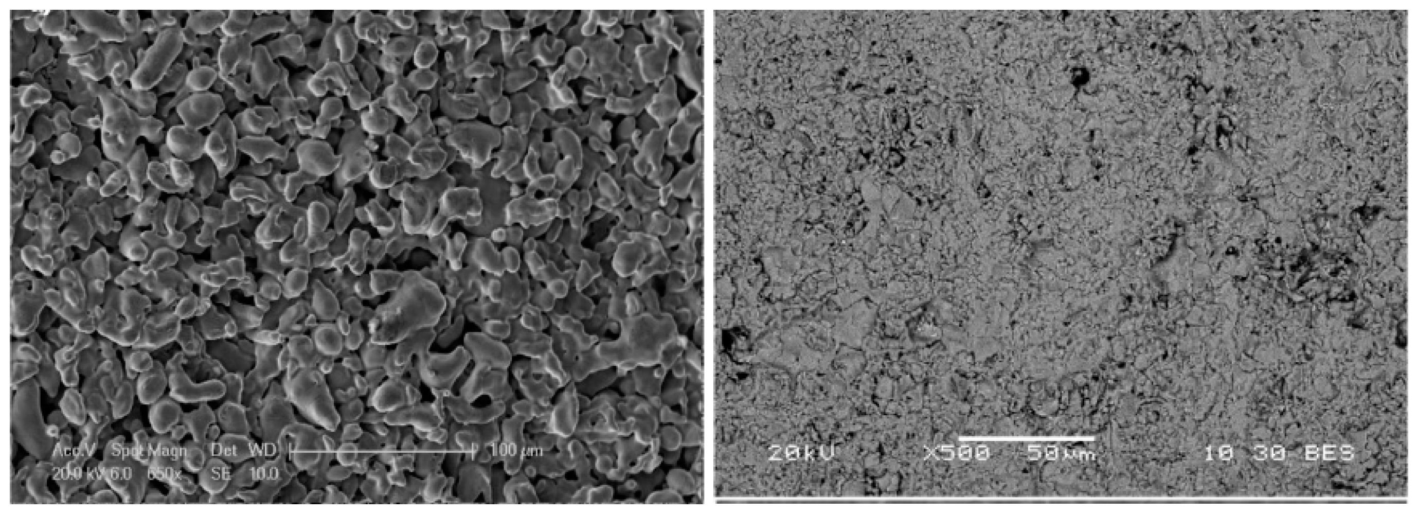
To select the powder that provides smaller surface roughness, the research group from Universidad Rey Juan Carlos (URJC) [
125] studied and reported the porosity and roughness of the intermediate layer of different commercial YSZ particles obtained by atmospheric plasma spraying (APS) on top of PSS with media grade of 0.1 μm.
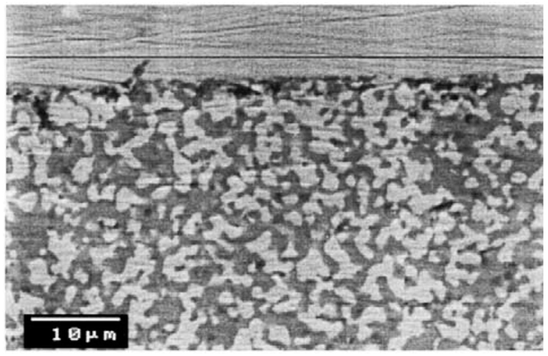
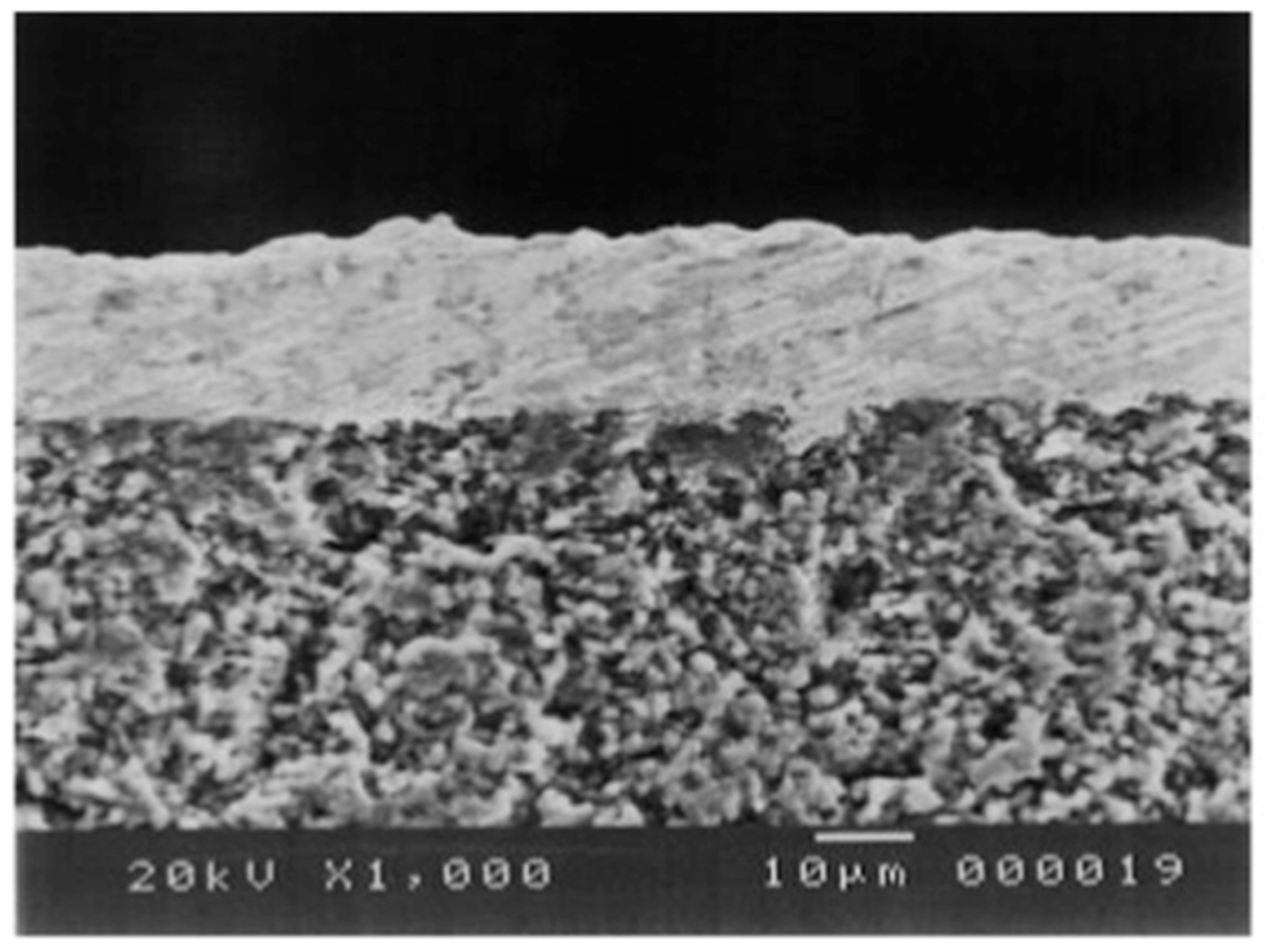
The initial porosity of the support (20%) was reduced to 2% by the intermediate YSZ layer made by Nanox s4007 and AMDRY 6600. The selected YSZ powder was Nanox s4007 since the deposited 100 μm thick layer presented the smallest average roughness (Ra = 2.89 μm) compared to the value measured with AMDRY 6600 (Ra = 4.73 μm) and original supports (Ra = 5.87 μm). The differences in surface quality of the original porous support and YSZ-modified with Nanox s4007 are shown in
Figure 7. It is clear from the pictures that the layer completely covered the support and at the same time a reduction in pore size was achieved. A 13.6 μm thick Pd-membrane was deposited by ELP onto YSZ/PSS. No nitrogen leaks were detected during single gas tests of the Pd-composite membrane, where the best hydrogen flux measured at 400 °C and a trans-membrane pressure of 2.5 bar was 0.062 mol∙m
−2∙s
−1. This flux dramatically decreased in the presence of CO and CO
2 during gas mixture tests with 70 mol % H
2. The initial H
2 flux was, however, recovered after removing all gas mixtures, thus the reduction is to be attributed to the very well-known CO poisoning of the membrane surface [
82].
Zhang et al. [
145] pre-treated PSS (316L) disks with large media grade (0.5 μm) by polishing with #3000 carborundum sandpaper followed by oxidation at 800 °C during 8 h. The measured nitrogen permeance at room temperature was 3.13 × 10
−6 mol∙m
−2∙s
−1∙Pa
−1, which was two orders of magnitude smaller than for the original support. A larger N
2 permeance was obtained (1.21 × 10
−5 mol∙m
−2∙s
−1∙Pa
−1) with thick YSZ layers of 2.5–3 μm deposited directly onto the supports by dip-coating. Diffusion of components from the porous support was suppressed only with YSZ at 700 °C. An 11 μm thick Pd layer was deposited onto an YSZ/PSS substrate by ELP technique. The hydrogen permeance of the composite was 1.05 × 10
−3 mol∙m
−2∙s
−1∙Pa
−0.5 at 650 °C and a pressure difference of ~220 kPa. The ideal H
2/N
2 selectivity was not reported, however N
2 was observed at room temperature and 100 kPa of pressure difference (10
−1 mol∙m
−2∙s
−1∙Pa
−1). On the other hand, a thicker Pd layer (25 μm) was deposited onto oxidized PSS, which suffered from intermetallic diffusion at 650 °C, since the hydrogen flux started decreasing after a few h. The authors suggested high atomic vibrations of elements from stainless steel and palladium, since they were exposed to temperatures above their Tamman temperature (316 L, 560 °C; Pd, 640 °C). The hydrogen permeance was measured at 600 °C and the same pressure difference as for the thinner membrane resulting in one order of magnitude smaller permeance (1 × 10
−4 mol∙m
−2∙s
−1∙Pa
−0.5) at the same temperature.
Interdiffusion barriers of mixed Al
2O
3-YSZ were deposited on top of Hastelloy X (0.2 μm media grade) by APS and powder suspension deposition (dip-coating) [
132]. The roughnesses for layers deposited by APS were found to be larger than by dip-coating. A 4–5 μm thick PdAg layer was deposited by ELP on top of a modified support with a ceramic interdiffusion layer deposited by dip-coating, and the measured hydrogen permeance was 7.69 × 10
−4 mol∙m
−2∙s
−1∙Pa
−0.5 at 400 °C and 100 kPa pressure difference. The measured H
2/N
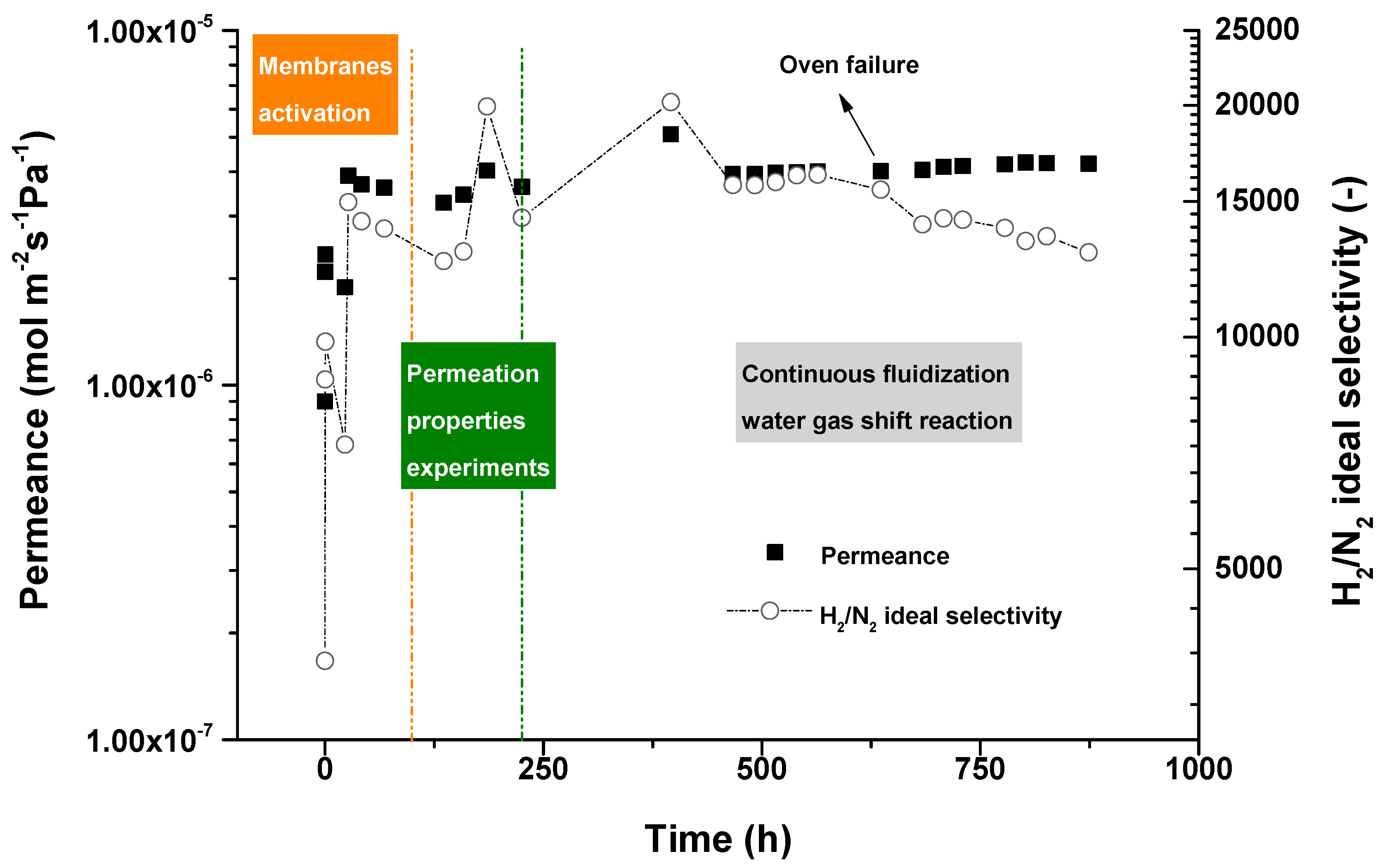
2 perm-selectivity was over 200,000. A long-term test with this membrane was performed by Medrano et al. [
62] during 800 h in the temperature range of 500–600 °C. The ideal perm-selectivity was maintained over 200,000 during 795 h. Nonetheless, defects started being formed at high operating temperatures (600 °C) and the ideal perm-selectivity dropped to 2650.
Oxidation of metallic supports allows growth of an Fe-Cr oxide (Cr
2O
3) layer in order to prevent diffusion of support elements to the selective layer. Ghabiri et al. [
122] oxidized a porous stainless steel 316 L disk (nominal particle retention size of 0.2 μm) in air at 800 °C for 12 h before the depositing a Pd
90.2Ag
3.6Cu
6.2 layer by electroless plating. A very thick selective layer, 40 μm, was required to avoid the presence of defects. The thickness and pore size of the grown oxide was not reported. However, it can be expected to be of the order of nanometers with a small reduction of the initial pore size of the supports.
Deposition of a 4 times thinner Pd layer (10.2 μm) by electroless plating was achieved by Sanz et al. [
54] as the retention size of the used PSS was 0.1 μm. Since the initial pore size of supports is small, the required thickness for the creation of a defect-free dense layer is decreased. Fe-Cr oxide was obtained at lower temperatures (650 °C) also for 12 h. Again the thickness of the Fe-Cr oxide was not reported. The membrane was first tested with pure hydrogen before being used with syngas in a packed-bed membrane reactor. The best permeation results were obtained in pure hydrogen at 400 °C and a pressure difference between retentate and permeate sides of 2.5 bar, obtaining a hydrogen flux of 0.054 mol∙m
−2∙s
−1 with an infinite ideal perm-selectivity (H
2/N
2), which indicates that the membrane was completely dense and defect-free.
However, it has also been reported that the generated oxide layer by oxidation in air on top of PSS substrates could not completely suppress intermetallic diffusion, as Samingprai and co-workers found [
147]. The authors compared oxidized PSS in air at 450 °C for 6 h with Cr
2O
3 layers of different thickness obtained by electrodeposition of Cr followed by oxidation at 700 °C for 6 h in air. Intermetallic diffusion was suppressed for a 2 μm thick Cr
2O
3 layer on top of substrates with an average pore size of 0.1 μm. The authors deposited Pd onto the modified supports by ELP until a dense film was achieved. A defect-free layer was obtained with a 32 μm thick layer which exhibited a low permeance due to the large thickness, 5.84 × 10
−5 mol∙m
−2∙s
−1∙Pa
−0.5 at 500 °C and a pressure difference of 100 kPa.
Summarizing, smooth surfaces are required in order to deposit a very thin selective layer without compromising the permeation rate. Also, it is well established that the mechanical stability of thin films is improved as they are supported. Chemical compatibility (avoiding interdiffusion of elements from metallic supports) and closer thermal expansion coefficients between the materials is necessary for long-term stability of the membranes.


 ,
, 


