1. Introduction
Since the invention of the laser, a vast demand on beam shaping has been verified in areas such as micro-fabrication [
1], optical sensing, optical trapping [
2,
3] of biologic samples or even medicine. Common beam shaping setups include several optical bulk components, which are mostly large and complex [
4,
5]. In contrast, optical fiber (OF) setups offer compact and cheap solutions for manipulation of light distribution.
The reshaping of optical fiber into tools for control of output field distribution has been implemented using several techniques and distinct types of fibers, such as: abrupt single mode tapers [
6], microstructured OFs [
7], chemically etched OFs [
8] and the combination of distinct OFs and micro-fabrication femtosecond laser machining [
9], among others. One particular application where the ability to control the fiber output beam profile is being explored, is in the development of optical fiber tweezers (OFT). OFT consist of a technological turning point since the trapping system can be implemented in a complete miniaturized form due to the small scale of the fibers [
10,
11] compared to normal setups [
12].
Different kinds of fiber micro structures have been reported creating output field gradients suitable to attain optical trapping effects [
13,
14]. Nevertheless, most of the presented fabrication techniques are either time consuming [
15] or expensive [
16,
17]. In particular, while chemical etching [
15] and thermal processes [
18] are low cost techniques, they are limited to conical and spherical designs, respectively. On the other hand, micro fabrication processes that use FIB milling [
16] and femtosecond lasers [
19], allow the fabrication of versatile structures, but have the drawback of being expensive and time consuming.
In this regard, we present a rapid method based on photo-polymerization for fabrication of micro structures at the top of OFs to be used as single fiber optical tweezers. To our best knowledge, there is only one paper in the literature, which reports the optical trapping of particles using polymeric tips [
20]. In that case, the authors reported the trapping of particles using a counter propagating system, where the polymeric tips act as the guiding waveguides for the trapping wavelength. In this paper, on the other hand, the 2D optical trapping using a single optical fiber with a polymeric tip is reported for the first time.
The method presented here addresses the optimization of the fabrication process of fiber optic microstructures using guided wave photo-polymerization [
21]. In particular, the impact of the multi-mode characteristics of OFs, at the polymerizing wavelength (405 nm) is evaluated. It is shown that depending on the selected modal distribution different shapes of polymer structures can be obtained at the fiber tip. The modulation of output field distribution of the resulting polymer structures, at different wavelengths, is analyzed and compared. A polymeric micro tip fabricated with optimized excitation is demonstrated as an optical fiber tweezer in the manipulation of yeast cells. This paper is organized as follows: in the second section the fabrication process and some aspects of multimode propagation in step index OFs will be described, then, in the third section the polymer structures are presented, analyzed and validated as optical tweezers, finally in the conclusions some final remarks will be given about the work presented in this paper.
2. Experimental Section
The fabrication of the micro structures was based on a guided wave photo-polymerization process [
22,
23]. The reaction consists of linking monomers into cross-linked polymers using light as a trigger. The polymerization is initiated by a photochemical process induced by the energy of a radiation source of a proper wavelength. In addition to this, a photoinitiator can be used to support a reasonable rate of polymerization. This photoinitiator is normally a free-radical generator which can be excited either thermally or photo-chemically. In the second case, the free-radical is created from excited states by the photo-initiator. The reactive initiator free-radicals react with a monomer molecule, finally forming the polymer. The polymerization process happens in a fast chain reaction and will occur until an inhibitor stops it. In this particular case, the monomer used was pentaerythritol triacrylate (PETIA) which is a tri-functional acrylate monomer and the photo-initiator was Irgacure 819, which has a working wavelength range from 375 nm to 450 nm. Other photoinitiators can also be used to fit with visible or NIR wavelengths [
24,
25].
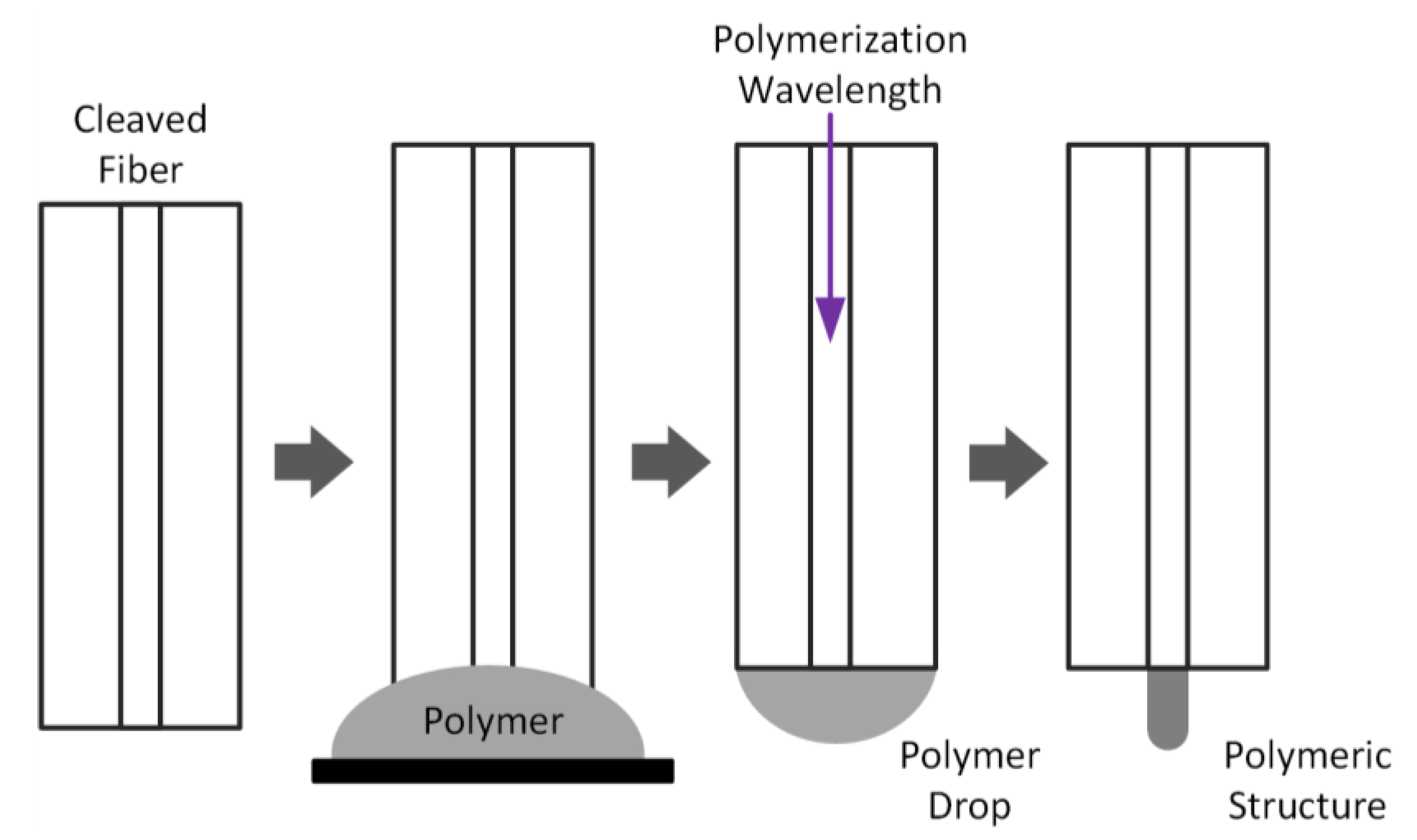
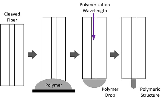
To fabricate the micro tips a diode laser (LuxX CW, 405 nm, 60 mW, Omicron) was coupled to an OF and used to illuminate the polymer placed at the extremity of the fiber, which was approximately 3 m long. The fabrication steps are depicted in
Figure 1. First, an OF was cleaved to form a flat end surface. Then it was placed on a support, and a drop of liquid was deposited onto the tip of the fiber. A laser beam (405 nm) was focused by an objective and thus coupled to the OF. The light emerging from the tip causes polymerization of the drop. After exposure (~ 10 s) the fiber was rinsed in ethanol and a polymeric tip was visible as an extension of the fiber core. The polymer tip is formed by a self-guiding photo-polymerization effect [
26]. As the polymer solidifies, its refractive index increases, creating a guiding effect that prevents the radiation from scattering in the remaining of the drop. The most important parameters governing the final geometry of the tip are: self-guiding effect due to change of refractive index during photo-polymerization, dye absorption at the polymerization wavelength and bleaching kinetic, inhibition reaction of polymerization due to reaction of radicals with oxygen. Their relative effect is discussed in reference [
24]. In the chosen conditions, the tip length is governed by the size of the photopolymer drop deposited at the end of the fiber while the radius of curvature at the extremity is determined by the photonic parameters (intensity and irradiation time).
Figure 1.
Fabrication process of polymeric structures at the extremity of optical fibers (OFs): the OF is first cleaved and placed vertically; then it is dipped in a drop of polymer; after this the drop of polymer is removed and the laser is turned on to illuminate the polymer on the top of the fiber; finally the fiber is rinsed in ethanol and the non-polymerized polymer is removed from the top of the fiber revealing the micro structure.
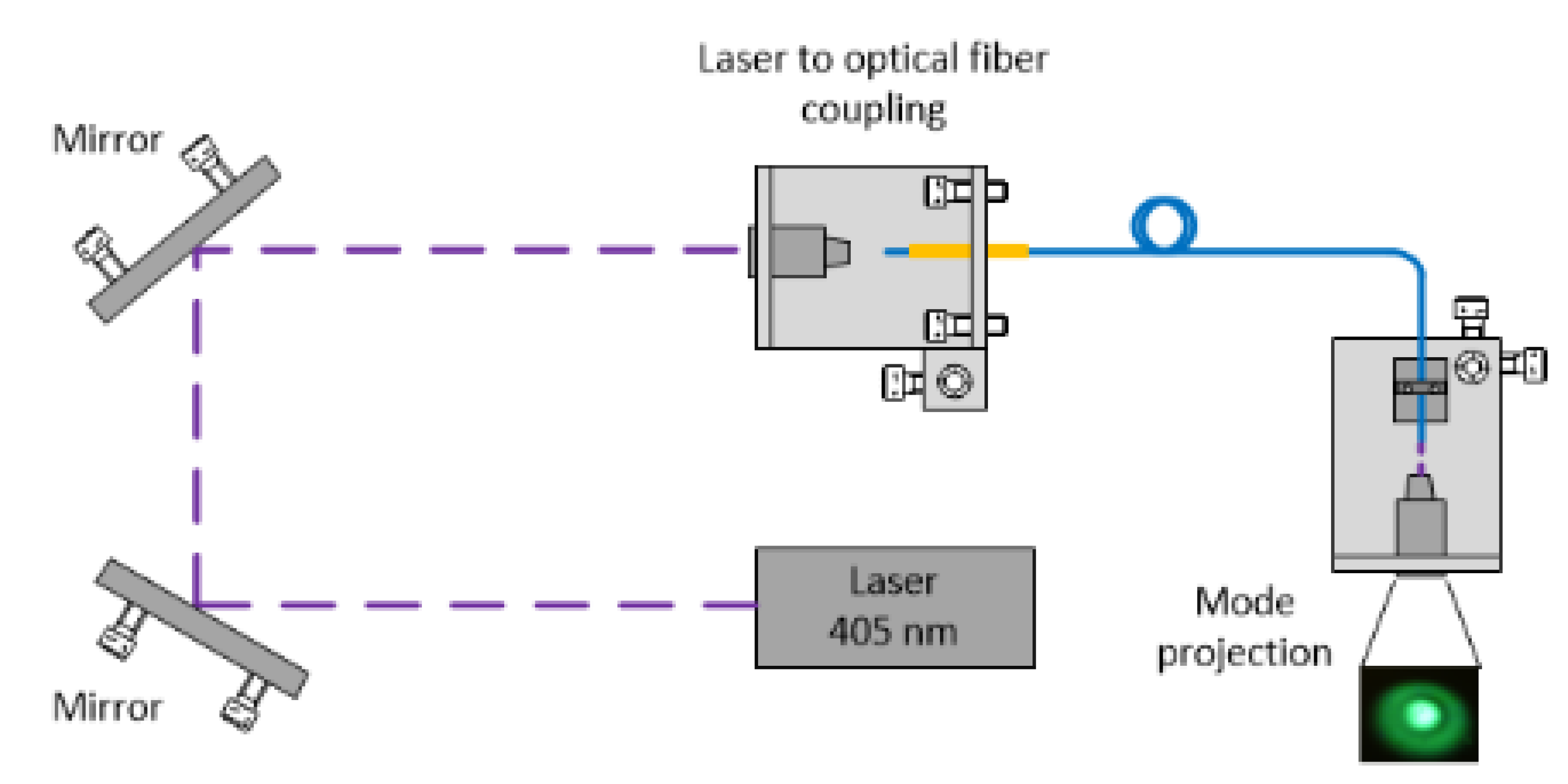
Figure 2.
Experimental setup used in the fabrication process of the polymeric micro structures. The optical modes are selected according to the light input angle. The light is coupled to the OF using a 10x objective. Using a second objective, the output modes are projected onto a flat surface.
Figure 2.
Experimental setup used in the fabrication process of the polymeric micro structures. The optical modes are selected according to the light input angle. The light is coupled to the OF using a 10x objective. Using a second objective, the output modes are projected onto a flat surface.
This fabrication process allows obtaining a considerable number of micro tips with distinct shapes and capable of producing a wide variety of output illumination patterns. In particular, the need to use a polymerizing wavelength bellow the fiber cut off results in the fiber supporting multiple modes, during the polymerization process. This way, depending on the modal excitation conditions distinct output intensity profiles will result during the polymerization stage producing different tip shapes. Such feature can either be a tool for designing new shapes, or a mechanism that will reduce the reproducibility of the fabrication technique [
23].
In the context of optical trapping, however, it is desirable that at the working wavelength of the tweezer the fiber should support only a single mode to guarantee stability and reproducibility of the output intensity pattern. In the present study the OFs used were SMF 980 (Thorlabs, SM980-5.8-125), which is a step index fiber. This wavelength was selected since it is frequently used in optical trapping experiments due to its low damage on biological samples [
27].
The number of modes that a multimode step index fiber supports is defined by the normalized cutoff frequency (ν), which depends on the wavelength (λ), the core radius (
a), and the refractive index of the core (
ncore) and the cladding (
ncladding). The normalized cutoff frequency is given by
For SMF 980 at 405 nm the normalized frequency is approximately 4.9. The single mode propagation is ensured when the
v parameter is smaller than 2.405, therefore this means that the SMF 980 will be a multimode waveguide at 405 nm, supporting approximately 12 distinct modes. At 980 nm the mode field diameter is 5.8 μm [
28].
Aiming to optimize the reproducibility of the fabrication of optical fiber tweezers, using this technique, a study was made on the impact of the modal selection on the resulting shape and corresponding output field distribution. During the fabrication, the selection of the excited mode of the SMF 980 was controlled by adjusting the input angle of the laser into the fiber. This was attained using an objective and two mirrors, arranged as shown in
Figure 2. More specifically, the beam input angles could be controlled either by adjusting the mirrors or by setting the controls of the alignment platform where the objective and the fiber were supported. The process of mode selection was then monitored using a second objective which projected the mode distribution onto a flat surface.
In the following section the experimental results obtained using the described setups and techniques will be presented.
3. Results and Discussion
In this work two types of tips having different shapes were fabricated by exciting distinct polarized modes of the SMF 980. The first tip was produced using the LP
02 mode illuminated with 4 µW@405 nm (measured at the end of the fiber using an optical power meter) during 10 s. The choice of the fabrication parameters was based on previous studies [
24]. For longer exposure times (of the order of some minutes) and/or higher power the pre-selected structure will not be imprinted on the top of the polymeric tip. In this case a flat surface will be fabricated instead. This is caused by the saturation of the polymer response due to the elevated dose. The LP
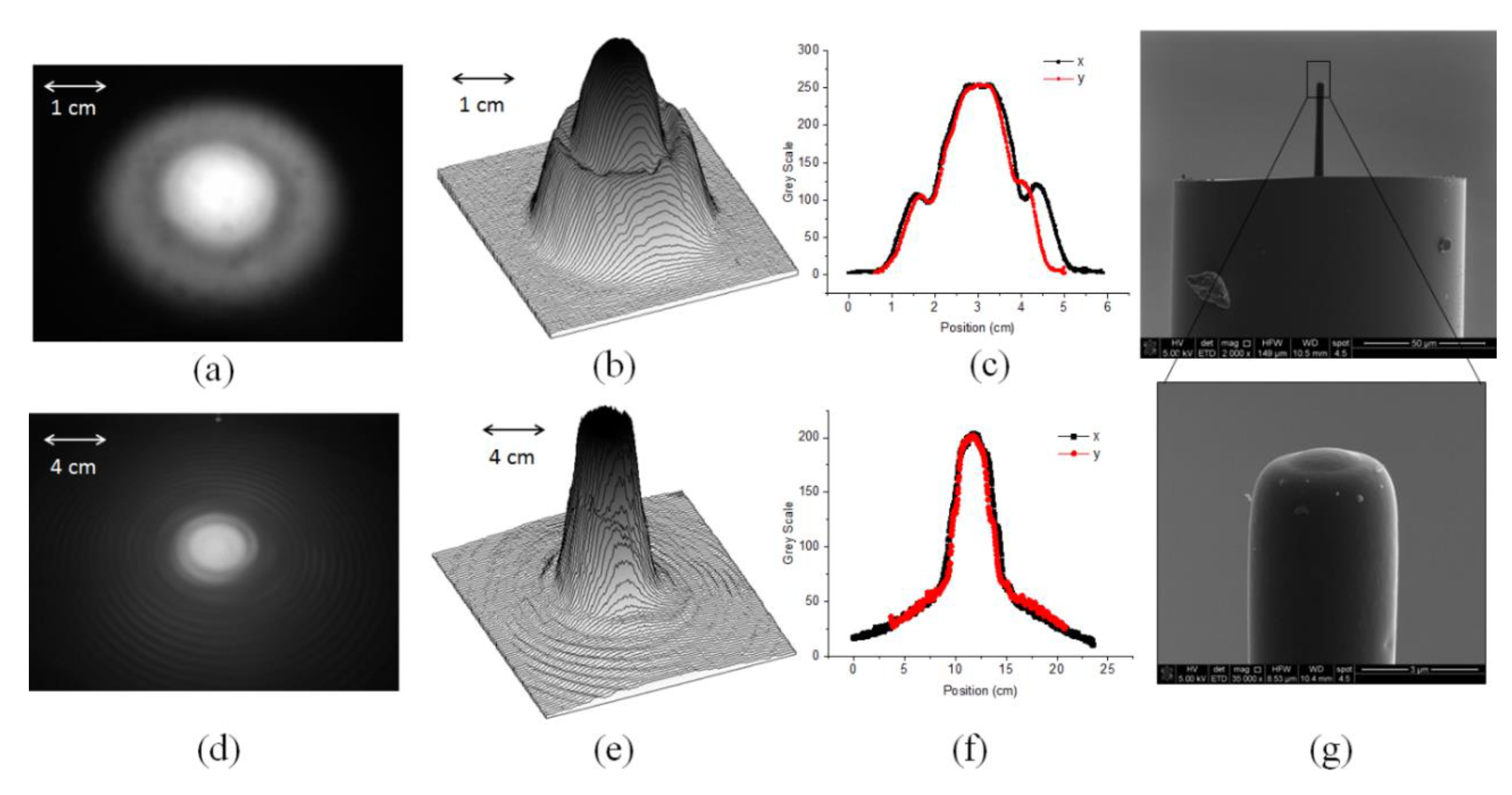
02 mode is composed by a concentric maximum and a surrounding ring, the intensity profile decreases from the center to the boundaries, presenting a minimum between the inner maximum and the surrounding ring. The excitation of this mode was verified by projecting the output field of the fiber on a flat target, and confirming the illumination pattern, as shown in
Figure 3a. Also, the image processing software ImageJ was used to recover the 3D pixel intensity profile, as depicted in
Figure 3b. In
Figure 3c the profile of the excited mode in the x and y axis are presented, confirming the characteristics of the primary beam.
The resulting structure was analyzed using SEM images, shown in
Figure 3g, where the structure at the end of the polymeric tip is presented in the inset. Notice that the profile of the end of the tip closely follows the intensity profile of the mode LP
02, which has two concentric maxima with radial symmetry. These two maxima result in a compound structure at the end of the tip: an inner structure close to the axis of symmetry with a curvature of ~1.5 µm and an outer annular structure (curvature radius ~2.5 µm) near the edge, both contributing for reshaping the field distribution. The tip has a diameter of the order of the diameter of the fiber modal diameter (~5.8 µm), and a length of ~40 µm. These structural parameters can be altered by adjusting the exposure time and the laser power. In order to investigate this, a study of the output curvature radius of the tip
versus the exposure time was performed. This demonstrated that for exposure times smaller than 15 s using an irradiation power of 4 µW the curvature radius was between 2.5 and 3 µm. For longer exposure times, bigger than 20 s, the curvature increases for 5 to 6 µm and in the limit tends to be flat.
After the fabrication, the tip was illuminated by a laser @980 nm and the output field profile was projected onto a flat target and analyzed, as previously done for the 405 nm laser beam. The resulting output pattern is shown in
Figure 3d which corresponds to a Gaussian like profile with a well-defined maximum and radial symmetry. As expected, the illumination pattern @405 nm and 980 nm share similarities. Even though the guided mode @980 nm has a Gaussian profile, corresponding to a LP
01 mode, after passing through the tip it acquires a profile with some similarities to the LP
02 mode (
Figure 3e). This is most visible in
Figure 3e than in
Figure 3f, where the x and y profiles are still more similar to a Gaussian. The imprinting of the radial characteristics of the original polymerizing beam, into the illumination pattern of the structured tip, results from the features of the fabricated polymer structure. Although the modulation is almost imperceptible it can have impact on the final features of the resulting tweezer showing the importance of controlling the modal excitation during the fabrication process in order to ensure the reproducibility of the process.
The second type of tips fabricated intended to verify if more complex patterns of the initial polymerizing beam (@405 nm) could be imprinted into the polymeric structure illumination pattern (@980 nm).
Figure 3.
Data collected from the fabrication of the first polymeric tip: (a) excited mode LP02 projected by the cleaved OF before the growth of the tip at 5 cm; (b) 3D pixel intensity profile of the excited mode LP02; (c) cross section along x and y direction of the excited mode; (d) field intensity profile projected by the fabricated polymeric tip at 10 cm (fiber tip coupled to a pigtailed SM 980 laser diode); (e) 3D pixel intensity profile of the field projected by the micro tip; (f) cross section along x and y direction of the projected mode; (g) SEM image of the polymeric tip.
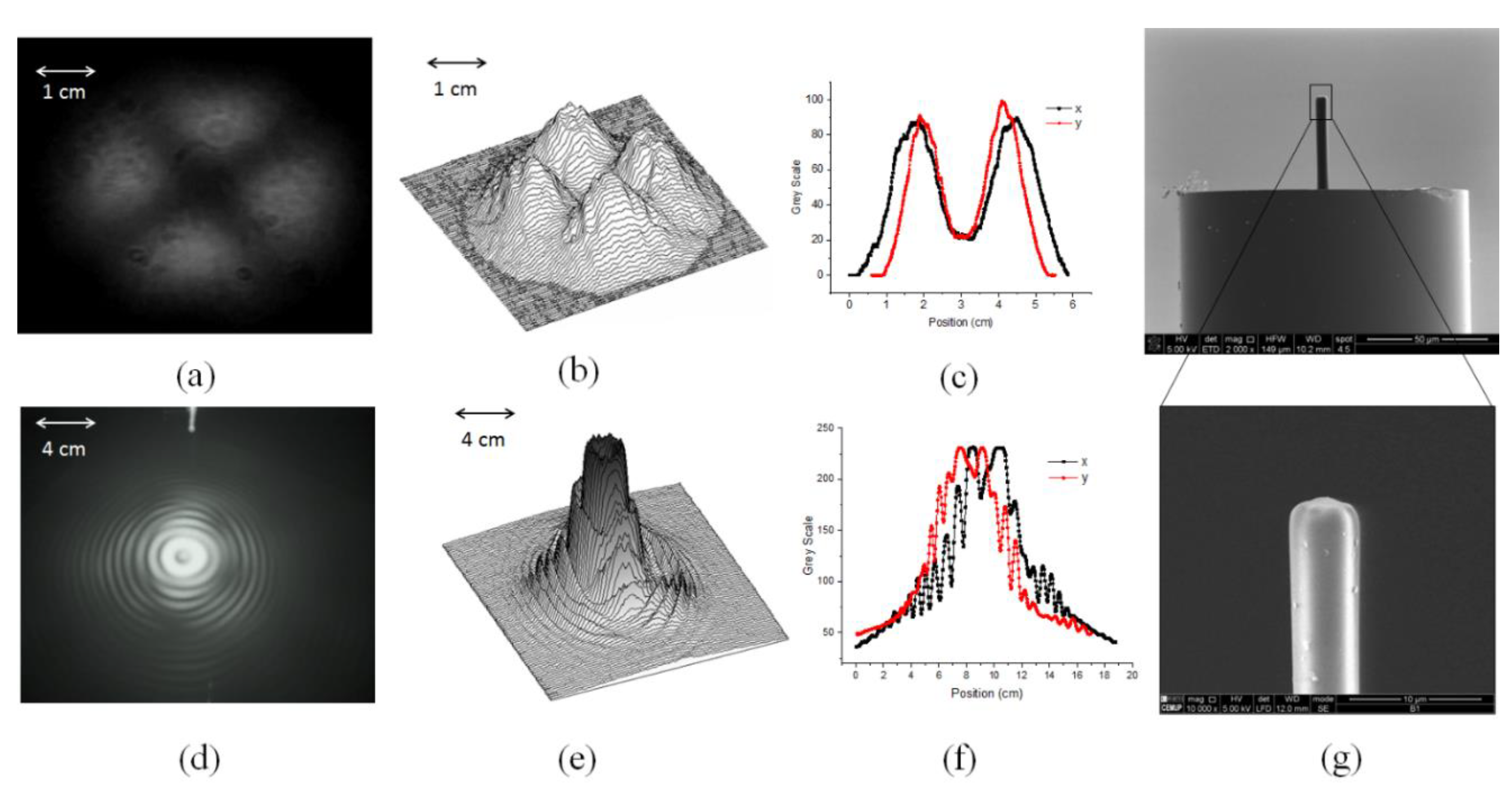
This second type of structure was fabricated by exciting the LP
21 mode (@405 nm) with a power of 4 µW and 10 s exposure. The LP
21 mode is composed by four intensity maxima arranged in a circular distribution with a zero at the center (see
Figure 4a,b). During the fabrication the LP
21 mode was efficiently excited, however, due to residual excitation of lower order modes some superposition with the output pattern of other modes was also noticed, as can be seen in the intensity profiles obtained by performing the cross section of plot of
Figure 4b along the
x and
y (
Figure 4c). As a result, the intensity at the center of the fiber was not exactly zero, due to the contribution given by other modes (
Figure 4f) superposed to the excited one, LP
21. Nevertheless, the LP
21 mode prevails and the fabricated structure mimics its intensity profile, as expected. This is confirmed by the SEM images shown in
Figure 4g. Notice that the non-zero light intensity at the center of the structure, produced by the superposition of the LP
21 mode with other modes, results in a non-zero intensity at the center causing further polymerization in this region. This causes the smoothing of the features at the end of the tip, avoiding that a much more defined hollow structure is obtained in the center of the four lobes. In this case the diameter at the base of the structure is ~4−5 µm and the length is ~38 µm.
The output intensity profile obtained when illuminating with a 980 nm laser is presented in
Figure 4d,e. As in the previous tip the structural features of the polymerizing beam (@405 nm) are imprinted (at least partially) into the polymeric structure and in its resulting illumination pattern (@980 nm). In particular, the radial symmetry of the input Gaussian beam (@980 nm) is broken as it goes through the polymeric structure, resulting in a beam profile which shares similarities with the mode LP
21. These results suggest that filtering out the input beam @405 nm to have a more pure LP
21 mode would result in a better defined structure and ultimately in an improved beam shaping @980 nm.
Figure 4.
Data collected from the fabrication of the second polymeric tip: (a) excited mode LP21 projected by the cleaved OF before the growth of the tip; (b) 3D pixel intensity profile of the excited mode LP21 at 5 cm; (c) cross section along x and y direction of the excited mode; (d) field intensity profile projected by the fabricated polymeric tip (fiber tip coupled to a pigtailed SM 980 laser diode) at 10 cm; (e) 3D pixel intensity profile of the field projected by the micro tip; (f) cross section along x and y direction of the projected mode; (g) SEM image of the polymeric tip.
These results provide the possibility to perform a simple preliminary analysis concerning the reproducibility of the fabrication of the polymer micro structures by the proposed technique. It was verified that, when other than the fundamental mode is excited, complex structures arise that results in altered output field patterns. Adequate characterization of these structured patterns require more advanced characterization methods that can also reveal details regarding the phase information of the output beams. Such approach will be further investigated using an interferometric setup, where a Gaussian beam is combined with the output beams under analysis. From this analysis, some guidelines for the fabrication of polymer micro tips applied to optical trapping can be extracted. It is clear that control of modal excitation must be implemented for reproducible fabrication. Excitation of fundamental mode allows us to obtain a structure with good quality and a Gaussian beam profile. Higher order modes result in more complex structure and output field profiles and its application requires a more detailed study. Indeed, it was verified that, without control of the modal distribution during the fabrication, the process reproducibility was very poor. On the other hand, after implementing controlled excitation of the fundamental mode the fabrication process was extremely reproducible.
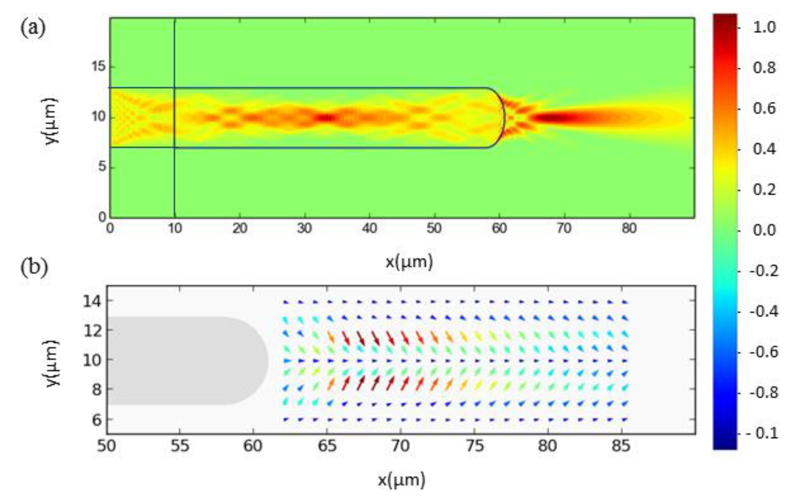
In other to access the applicability of the polymeric structures a preliminary study was made, where the trapping ability of an ideal polymeric tip was evaluate numerically. To do the simulations an implementation of the finite differences time domain, MEEP, was used to solve the stationary electromagnetic field in a 2D system composed by a waveguide (n = 1.52), in water (n = 1.32). In
Figure 5a we can see a 2D simulation of the electric field intensity resulting as the output of a waveguide with a curvature radius of 3 µm, @980 nm. In this figure we can see that the beam is focused by the polymeric diffractive structure. Then, with the field distribution obtained from the MEEP solver and considering a dielectric particle (n = 1.42, r = 2.5 µm) the total force acting on it was calculated, based on the Lorentz description [
29]. The results clearly show that the field distribution arising from diffractive effects at the fiber tips, creates strong field gradients necessary to generate the trapping point with zero net force acting on the particle. Such indications were verified experimentally, using polymeric tips fabricated as described above.
Figure 5.
Simulated electric field profile (a) and force distribution (b) caused by a polymeric tip.
Figure 5.
Simulated electric field profile (a) and force distribution (b) caused by a polymeric tip.
Some preliminary results on fiber optical trapping were obtained using a fiber with a tip fabricated with a Gaussian profile (LP
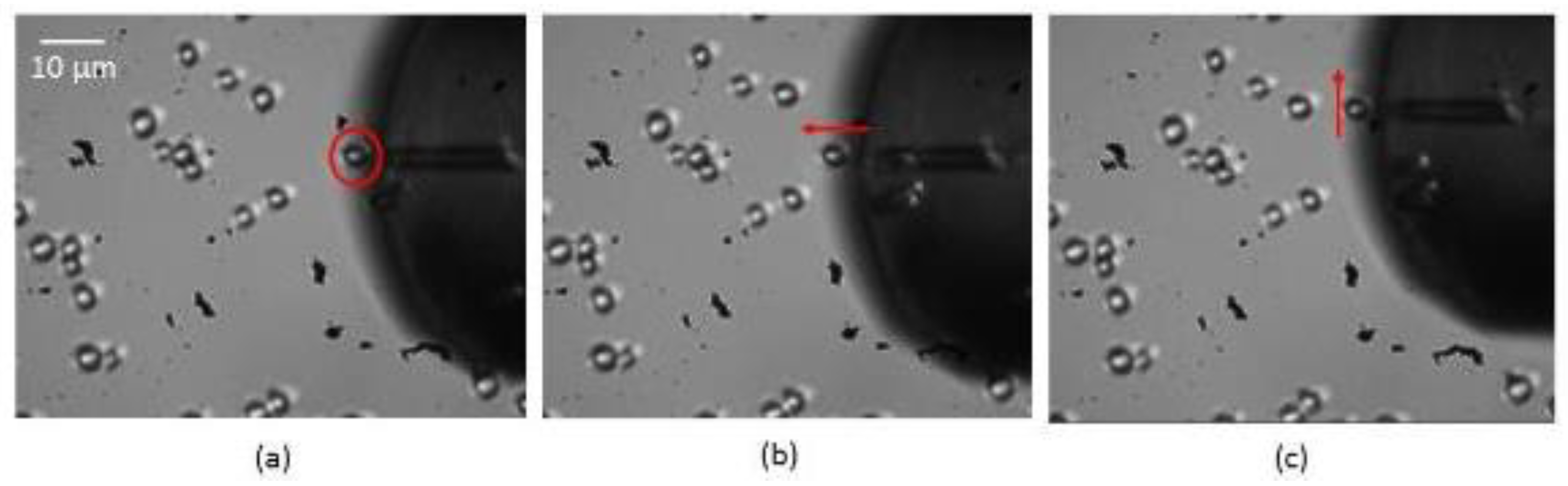
01 mode). In the fabrication process, the exposure time was 10 s and the polymerization laser power 4 µW. The resultant structure had a length of 25 µm and a curvature radius of ~ 3 µm. The fiber probe was attached to a micromanipulator and installed in an inverted microscope setup. A diluted solution was prepared with yeast cells. The tip was controlled by a motorized setup allowing to place it in the vicinity to one of the cells. When the laser @980 nm (Lumix, LU0980M500) is turned on, the output beam of the micro tip produces an output beam with a field profile gradient that generates an optical force able to immobilize and manipulate micro particles. In this particular case a yeast cell of ~5 µm, was trapped, using 40 mW power, and moved in the xy plane. To illustrate this phenomena, in
Figure 6, three pictures are shown, which were obtained consecutively. Several cells are shown, the one in front of the fiber tip was trapped by the light field (marked red in
Figure 6a). By moving the fiber tip forward, the trapped cell is also dragged along, then moving the fiber to the right, the cell moves as well. In contrast, when the laser is turned off, and the fiber is moved, the cell will no longer be trapped. From the video frames the trapping distance can be estimated as approximately 6 µm away from the polymeric tip. Furthermore, using the Drag method [
12] to calculate the force acting on the cell, a maximum value of 0.37 pN was determined. Overall, these results demonstrated for the first time that, with optimized fabrication conditions, it is possible to obtain 2D optical trapping using a single optical fiber with a polymeric tip.
Figure 6.
Demonstration of the use of the polymeric structures as an optical tweezer for the manipulation of yeast cells: (a) the cell in front of the fiber is trapped by the field gradient and (b) it is pushed forward while the fiber is moved; (b) the cell is moved to the right (in relation to the fiber).
This procedure paves the way for obtaining other complex structures having a strong potential for a diversity of applications, such as mode communication [
30,
31], advanced optical trapping [
11,
32,
33], among others. Indeed, more complex beams, such as LP
21 are now being studied for the rotation of particles and cells trough the angular momentum transference. This is caused by twisting and/or bending the fiber, causing the mode to rotate, and consequently the cell as well [
33]. The torque effect caused by rotation of the LP
21 mode is similar to orbital angular momentum carried by Vortex beams and consequent rotation of micro particles. Similar effects can be explored by adjusting the wavelength and injection angle of the radiation going through the polymeric microstructure.


