A Hybrid DC–DC Quadrupler Boost Converter for Photovoltaic Panels Integration into a DC Distribution System


Electrical Engineering Department, Faculty of Engineering, Najran University, Najran 66446, Saudi Arabia
Electronics 2020, 9(11), 1965; https://doi.org/10.3390/electronics9111965
Submission received: 16 October 2020
/
Revised: 15 November 2020
/
Accepted: 16 November 2020
/
Published: 20 November 2020
(This article belongs to the Special Issue Design, Modeling and Control of Power Electronic Converters for/in Renewable Energy Systems)
Abstract
:This paper presents a non-isolated DC–DC boost topology with a high-voltage-gain ratio for renewable energy applications. The presented converter is suitable for converting the voltage from low-voltage sources, such as photovoltaic panels, to higher voltage levels. The proposed converter consists of a multiphase boost stage with an interleaving switching technique and a voltage multiplier cell to provide a voltage level at a reduced duty cycle. The interleaved boost stage consists of two legs and can be either fed from single or multiple voltage sources with the ability to control each source separately. The voltage multiplier cell can increase the voltage level by charging and discharging the capacitors. Several advantages are associated with the converter, such as reduced voltage stress on semiconductor elements and a scalable structure, where the number of voltage multiplier cells can be increased. The inductors in the interleaved boost stage share the input current equally, which reduces the conduction loss in the inductors. The input and the output of the converter share the same ground, and all active switches are low-side, which means no feedback or signal isolation is required. The theory of operation and steady-state analysis of the converter operating in the continuous conduction mode is presented. Components selections and efficiency analysis are presented and validated by comparative analysis and simulation results. A 0.195 kW experimental prototype was designed and implemented to convert the voltage from 20 V input source to 400 V output load, at 50 kHz. The test results show a high-performance of the converter as the maximum efficiency point is above 97%.
1. Introduction
The number of renewable energy sources (RES) installations has been increasing since the end of the 20th century. Several factors contribute to the increase of the RES adoption. First, renewable energy sources are a viable solution to both the energy shortage and environmental pollution. Secondly, the price of material and the manufacturing cost have been substantially declining [1,2]. Several programs and projects are subsidized by the governments to stimulate the energy markets, such as One Million Solar Roof Initiatives in 1997 [3] and the Rural Energy for America Program [4]. The growth of the renewable energy market has driven the research and developments of recent applications and technologies that enable RES deployments, such as DC microgrids and DC distribution systems. The DC distribution system has been attracting researchers’ attention due to the advantages the DC distribution system has over the AC distribution system. The DC distribution system requires fewer converter units, and it has several advantages, for instance, high-efficiency, high power quality, low cost, and the suitability for renewable energy integration [5,6]. Most renewable energy sources feature low-output voltage, such as photovoltaic panels, and the integration into a DC distribution system is challenging. The PV panels typically have a voltage range of 15–45 V [7], and the DC distribution system has a voltage of 360–960 V. Therefore, a step-up DC–DC conversion with a large voltage-gain ratio unit is needed to facilitate the integration.
The simplest step-up topology is the traditional boost converter. The traditional boost converter’s power stage contains only four components: a coil, a low-side MOSFET, a diode, and a capacitor [8]. However, achieving a high-voltage-gain ratio out of the traditional boost converter necessitates operation at a high duty cycle. Ideally, the voltage gain could be very high as the duty cycle approaches unity. Still, in practice, the voltage gain at high duty cycles becomes insufficient due to the inductor and MOSFET conduction losses [9]. The traditional boost converter is not a preferred solution to provide high output voltage because the voltage stress across the diode is equal to the output voltage. This might compel the designer to select inefficient and expensive components. In addition, the critical inductance that ensures continuous conduction mode operation is large, so the power density is decreased [10]. Thus, a multilevel converter such as a three-level step-up converter was mainly proposed to minimize the magnetic elements size and voltage stress across components [11,12]. Nevertheless, the three-level step-up converter’s gain is similar to the one of the traditional boost converter.
Cascading multiple boost converters allows operation at low duty cycles and enhances the overall voltage gain [13,14]. However, such an approach’s efficiency is lower because the power is processed multiple times, and the output diode is required to block the high output voltage. Flying capacitor multilevel converters can boost the input voltage to the desired output voltage with reduced voltage stress across its internal components. Moreover, the inductor required to ensure continuous conduction operation is very small due to the virtual frequency seen by the inductor. The virtual frequency is several times higher than the switching frequency, which depends on the number of stages [15,16]. The flying capacitor is dependent on the phase shift modulation. The higher the number of voltage stages, the higher the minimum duty cycle that is necessary. Increasing the number of stages limits the duty cycle’s operation to a narrow range, making the converter not suitable for applications such as tracking control and load matching.
Another approach used to increase the voltage gain is by employing a coupled inductor or transformer, which can also be utilized to provide isolation [17,18,19]. The use of magnetic devices makes the output voltage a function of the turns ratio, which allows the design at any desired duty ratio. The disadvantage of utilizing coupled inductors or transformers is the voltage spikes across the semiconductor switches caused by leakage inductance. To overcome that, an extra snubbing circuitry is required to circulate the energy. Using a transformer or coupled inductor takes a large area of the hardware prototype, and hence the converter’s power density is reduced. Several research papers introduced multiple boost converters with interleaving technique hybridized with switched capacitors’ circuits [20,21]. Using such a method can significantly enhance the topology, where the switched capacitor increases the power density and minimizes the size of the magnetic elements. However, switch capacitor circuits require a complicated driving circuit and an advanced control scheme to eliminate the capacitors’ voltage mismatches. Replacing the switches capacitor cell with a voltage multiplier cell removes the complexity of gate drive circuitry and the signal isolation such as in [22,23,24,25]. However, the voltage stress across components still high and current sharing between phases is not equal, which compromises the efficiency. The limitation in existing topologies motivates the research in this paper.
The proposed converter comprises a two-phase boost stage with an interleaving technique, an intermediate capacitor, and voltage multiplier cells. The advantages of the presented converter are:
- The two-phase boost stage with interleaving reduces the current ripples on input current, doubles the ripple frequency, makes it easy to be filtered, and allows precise current measurements to enhance the maximum power point tracking.
- The converter offers high-voltage gain and, at the same time, low voltage stress across both active and passive components.
- The proposed converter has a modular structure and can be extended to reduce further the operating duty cycle and voltage stresses across the components.
- The output of the converter shares the ground with input sources. Thus, the output voltage can be sensed through a voltage divider and no need for expensive differential voltage sensors and isolated feedback loop.
- The proposed converter can operate in continuous conduction mode (CCM) with smaller inductance. Therefore, higher power density can be achieved.
- The average current of both inductors are equal, so that conduction loss is at its minimum since the conduction loss is a quadratic function of the inductor RMS currents.
The rest of the papers are organized as follows: Section 2 presents the operation principle and derivation of steady-state equations. Section 3 presents converter design and efficiency analysis. In Section 4, comparative analysis with several high-voltage-gain converters is presented. Section 5 presents simulation results, details about hardware implementation, and experimental results are provided and discussed. Finally, the summary and key points are presented in Section 5.
2. Principle of Operation and Derivation of Steady-State Equations
The converter consisted of a two-phase boost stage, an intermediate capacitor, and a diode capacitor cell to multiply the voltage. The two-phase boost stage uses two low-side MOSFETs and an interleaving technique to share the input current between inductors. The interleaving technique reduces the magnetic volume and increases the source current ripples’ frequency to be filtered. Figure 1a shows the proposed converter with one stage voltage multiplier cell. The voltage multiplier cell is shown in Figure 1b, which comprises three diodes and two capacitors. The proposed converter has a general, flexible structure. That is, the voltage gain could be increased by arranging voltage multiplier cells consecutively, as shown in Figure 1c. However, increasing the number of voltage multiplier cells increases the total conduction loss of the diodes. Throughout this paper, a single voltage multiplier cell stage is used to provide complete analysis and implementation. The proposed converter has three modes of operation, which are governed by two control signals, as shown in Figure 2. Mode 1, where both switches are on, always comes between mode 2 and mode 3. To perform the analysis of the circuit in these modes, few assumptions were made to simplify the analysis. (1) The elements are lossless, (2) the converter operation is in the steady-state, (3) the duty cycle of both MOSFETs are equal, and they are out of phase with (4) all capacitors being large enough to neglect the voltage ripples.
2.1. Mode 1: The MOSFETs Are Both Conducting
Mode 1 occurs twice during a switching period in and . Both MOSFETs are conducting in this mode, and both inductors are drawing energy from the input source. Hence, all diodes are in the reverse-bias mode, and they are OFF. Therefore, the voltage multiplier cell is disconnected from the interleaved boost stage. The equivalent circuit of this time interval is illustrated in Figure 3a. The state equations of this interval are given by
2.2. Mode 2: Is OFF and Is ON
In this mode, diodes and are forward-biased, and they are conducting. The inductor is still drawing energy from the source, while the energy of is being transferred to the voltage multiplier cell capacitors. The diodes and are in reverse-bias, and they are blocking in this interval. The capacitors and are being discharged to the output load and capacitor . The equivalent circuit of the converter in this interval is shown in Figure 3b. The state equations are calculated by
2.3. Mode 3: Is ON and Is OFF
This mode is opposite to the previous mode. The diodes and are forward-biased, and they are conducting while the diodes and are reverse-biased, and they are OFF. The capacitor is drawing energy from the input voltage and the inductor . Inductor is being charged from the input voltage. The capacitors and and are connected in parallel and, therefore, the energy in is being discharged to . The equivalent circuit of this interval is shown in Figure 3c. The state equations of this interval are given by
2.4. Steady-State Static Voltage Gain
The voltage-second balance is used to derive the steady-state equations. Thus, the average value of the inductors is given by
From Figure 3 and the inductor current equations, one can find the relationship between the voltages in the circuit. The relationship between capacitors voltage and input voltage is given by
By solving (7), one can obtain the voltage across capacitors. The voltage of the intermediate capacitor is given by
The voltage across voltage multiplier cell capacitors is given by
and the output voltage is given by
In case the converter has N of voltage multiplier cells, the static voltage gain of the converter is calculated by
The ideal voltage gain of the converter at a various number of voltage multiplier cells is shown in Figure 4. One can obtain a high voltage gain at a reduced duty ratio by adding an extra number of voltage multiplier cells. However, increasing the number of voltage multiplier cells increases the bill of material and the c. The primary source of non-idealities is diodes. The voltage gain considering the forward voltage of the diodes (Vf) is calculated by
The previously detailed analysis in this paper was for the case of one independent source and the same duty cycle of the MOSFETs. The presented converter can take power from multiple independent sources, where each independent source is connected to a phase. For example, two different PV panels with different voltage levels can be connected in parallel and controlled separately. The connection of two independent sources is illustrated in Figure 5. Each phase can work at a different duty cycle than the other, which is applicable to track an individual PV panel’s maximum power point. Table 1 summarizes the voltage gain in the case of two independent sources and various duty cycles cases:
3. Converter Design and Efficiency Analysis
The selection of the most suitable components ensures the converter’s proper operation and enhances the quality of the overall design. This section presents information about components ratings, maximum stresses, and currents.
3.1. Inductor Selection
As previously mentioned, the input current is equally shared among the phases. The average current passing through each inductor is given by
The current ripple of the inductor current is calculated by
The proposed converter is intended to work in the continuous conduction mode (CCM). Therefore, the critical inductance that ensures the proposed converter operates in the CCM is given by
However, the inductors are usually selected based on the desired tolerance of current ripples, which is typically less than 30%. The peak current of the inductor is given by
The RMS current is given by
3.2. MOSFET Selection
The voltage across the MOSFETs is given by the following:
The input current is shared equitably among inductors, and, therefore, the average value of the switch current is given by
and, for N voltage multiplier cells, the average currents can be calculated by
The effective value of the MOSFET current is given by
and for N voltage multiplier cells the effective value of the MOSFET current is calculated by
3.3. Diode Selection
The maximum voltage stresses across the blocking diodes are given by
The voltage stress on the output diode is calculated by
The voltage stress across blocking diodes could be generalized for N number of cells, which is given by
and the output diode voltage is given by
The average current value passing through diodes is equal to the output current
and the rms current can be calculated by
3.4. Capacitors Selection
Capacitors are required store energy during off-states and assist with multiplication of the voltage. The output capacitor current is given by
The voltage multiplier cell capacitors and rms current is given as
The capacitor rms current is given by
The rms current passing through voltage multiplier cell capacitors is not affected by the number of stages. The current of the intermediated capacitor , on the other hand, depends on the number of voltage multiplier cells, and is given by
The capacitance is selected based on the tolerated voltage ripples. The output capacitor needs to be large enough to supply the load during mode 1. The required output capacitance is given by
where is the switching frequency, and is the tolerated voltage ripples.
3.5. Efficiency Analysis
The conduction power loss in inductors can be determined by the RMS current, which can be calculated by
where and are the DC resistance. In case of and , the total conduction loss of the inductors is given by
The power losses in the MOSFETs can be approximated into two segments: switching loss and conduction loss. The switching loss of a MOSFET can be found using the following equation:
where is MOSFET output capacitor, and and are the ON and OFF time of the MOSFET, respectively.The conduction loss part is given by
where and are the ON resistance of the and , respectively. The power loss in the diodes is given by
where is the forward voltage and the forward resistance of the diode. The power loss in capacitors is given by
where the ESR is the equivalent series resistance of the capacitor. The total loss is given by
The power stage efficiency of the converter is calculated by
4. Comparative Analysis
Several high-voltage gain DC–DC step-up converters for renewable energy applications can be found in the literature [26,27,28,29,30,31,32]. In this section, the proposed converter is compared only to the converters that have shared ground between the input and the output, and do not have any floating active switch or coupled inductors. The selected existing converters are compared to the proposed converter in terms of the number of components, number of inductive and capacitive storage elements, voltage stress across switching devices, and the voltage gain. Table 2 shows a comparison of the proposed converter with other converters. The proposed converter has higher voltage gain compared to the conventional boost and the interleaved boost converters and lower voltage stress across elements. The converter in [33] has higher voltage stress across components than the proposed converter. The proposed converter has less number of components and higher voltage gain than the converter in [34]. The converter in [35] has a higher number of components than the proposed converter, and with slightly higher voltage gain. The input current in [35] is not equally shared between inductors. The conduction loss of the inductors in an interleaved boost converter is the lowest when the input current is shared equally among inductors. Figure 6 shows the difference of inductors conduction power loss between a converter with equal current sharing and one without equal current sharing between inductors. The difference can be up to 20 W of power loss at 5 A load current and a = 0.1 Ω.
5. Simulation and Experimental Results
The operation of the proposed converter was confirmed with simulation and experimental study. The parameters used in the simulation are listed in Table 3. In addition to simulation parameters, small parasitic elements were included to avoid singular loops and allow better simulation performance. The inductors voltage and current waveforms are shown in Figure 7. The average and RMS values of each inductor current are 5 A and ≃5.2 A, correspondingly. Figure 8 shows the voltage stress across the active switches and diodes. The maximum voltage across the active switches is 100 V, and the maximum voltage across the voltage multiplier cell diodes is 200 V, and the voltage stress across the output diode is 100 V. The current passing through MOSFETs is shown in Figure 9, where the RMS of the switches and are 5.25 A and 5.28 A, respectively. The average current passing through each diode is 0.5 A, and the effective value of the current is 1.11 A. The waveform of capacitors currents is shown in Figure 10. The RMS value of the currents of , , , and are 3.3 A, 1.65 A, 1.65 A, 1.65 A, and 1 A, respectively. The voltage across capacitors is shown in Figure 11. The voltage across the intermediate capacitor is 100 V, and the voltage across capacitors and is 200 V. The efficiency simulation was performed using the equations in Section 3.5. The loss breakdown and breakdown percentage in Figure 12 indicates the component loss value and percentage with respect to the total power versus the load power. The diodes MOSFETs share the majority of power loss, and their losses increase with the increase of load power, and they are culprits of more than 82% of the total power loss at full load. The inductors’ power loss comes after the switching elements, which share about 16% out of the total power loss at full load. Capacitors with low ESR have insignificant power loss compared to other elements.
The proposed converter was experimentally tested in the laboratory to verify the operation. A hardware prototype was designed and constructed to convert a 20 V supplied by programmable power supply to a load. Figure 13 shows the hardware setup of the experiment. The programmable electronic load BK8502 is used as a load, and an auxiliary voltage source is used to power the gate drive circuits. The power stage was constructed using the components listed in Table 4. The MOSFETs are implemented using , which has a voltage rating of 150 V and has low conduction loss due to low ON resistance. The coils are used for and . The inductors have 100 µH, which ensure CCM operation and smooth input current. Capacitors are all implemented using film capacitors with 10 µF and capability of operation at higher voltages. All diodes are implemented using a Schottky diode with low forward voltage and fast reverse recovery time. The experimental results are shown in Figure 14, Figure 15 and Figure 16. Figure 14 shows the controlling signal of the MOSFETs, which are provided by the signal generator and the voltage stress across MOSFETs and diodes. The voltage across capacitors and their ripples are shown in Figure 15. The voltage ripples of internal capacitors voltages are all less than 1 V, and the magnitude of output voltage ripples is less than 0.2 V. Figure 16 shows the currents in the interleaved boost stage. Similar to the simulation, the average value of the inductors current is 5 A. Due to the out of phase operation between the phases, the input current has a higher frequency and less current ripples. The converter’s efficiency has a maximum value of about 97% and occurred at 80 W. At full load, the efficiency is around 94.5%. The efficiency can be further improved by selecting more efficient switching elements.
6. Conclusions
This paper has presented an interleaved high-voltage-gain step-up DC–DC topology with voltage multiplier cells to convert 20 V to 400 V. The proposed converter has peak efficiency above 97% at 80 W, and full load efficiency is roughly 94%. The converter’s operation was explained by detailed analysis and verified by simulation and experimental results. The proposed converter has several advantages: a high-voltage-gain ratio, low voltage stress across the switching elements, and high efficiency. The input current is smoother than the traditional boost converter, suitable for sensing input current and obtaining accurate measurements. Future work includes controlling the proposed converter using a maximum power point tracking controller and integrating the converter to a 400 V distribution bus or connecting to an inverter to provide AC power to the main grid.
Funding
This research was funded by Najran University Grant No. NU/ESCI/17/076.
Acknowledgments
The author is thankful to the Deanship of Scientific Research at Najran University for funding this work through grant research code (NU/ESCI/17/076).
Conflicts of Interest
The author declares no conflict of interest.
References
- Katiraei, F.; Aguero, J.R. Solar PV Integration Challenges. IEEE Power Energy Mag. 2011, 9, 62–71. [Google Scholar] [CrossRef]
- Bialasiewicz, J.T. Renewable Energy Systems with Photovoltaic Power Generators: Operation and Modeling. IEEE Trans. Ind. Electron. 2008, 55, 2752–2758. [Google Scholar] [CrossRef]
- Li, Q.; Wolfs, P. A Review of the Single Phase Photovoltaic Module Integrated Converter Topologies with Three Different DC Link Configurations. IEEE Trans. Power Electron. 2008, 23, 1320–1333. [Google Scholar] [CrossRef] [Green Version]
- Blanchard, R. Property Assessed Clean Energy (PACE) Renewable Energy Program Plan and Pilot Project: On Behalf of Northport Energy Action Taskforce (NEAT) & Levin Energy Partners. Master’s Thesis, University of Michigan, Ann Arbor, MI, USA, 2017. [Google Scholar]
- Hegazy, O.; Mierlo, J.V.; Lataire, P. Analysis, Modeling, and Implementation of a Multidevice Interleaved DC/DC Converter for Fuel Cell Hybrid Electric Vehicles. IEEE Trans. Power Electron. 2012, 27, 4445–4458. [Google Scholar] [CrossRef]
- Dragičević, T.; Lu, X.; Vasquez, J.C.; Guerrero, J.M. DC Microgrids; Part II: A Review of Power Architectures, Applications, and Standardization Issues. IEEE Trans. Power Electron. 2016, 31, 3528–3549. [Google Scholar] [CrossRef] [Green Version]
- Kouro, S.; Leon, J.I.; Vinnikov, D.; Franquelo, L.G. Grid-connected photovoltaic systems: An overview of recent research and emerging PV converter technology. IEEE Ind. Electron. Mag. 2015, 9, 47–61. [Google Scholar] [CrossRef]
- Kazimierczuk, M.K. RF Power Amplifiers; Wiley Online Library: Hoboken, NJ, USA, 2008; Volume 1. [Google Scholar]
- Revathi, B.S.; Prabhakar, M. Non isolated high gain DC–DC converter topologies for PV applications—A comprehensive review. Renew. Sustain. Energy Rev. 2016, 66, 920–933. [Google Scholar] [CrossRef]
- Khadmun, W.; Subsingha, W. High voltage gain interleaved dc boost converter application for photovoltaic generation system. Energy Procedia 2013, 34, 390–398. [Google Scholar] [CrossRef] [Green Version]
- Yaramasu, V.; Wu, B. Predictive control of a three-level boost converter and an NPC inverter for high-power PMSG-based medium voltage wind energy conversion systems. IEEE Trans. Power Electron. 2013, 29, 5308–5322. [Google Scholar] [CrossRef]
- Kwon, J.M.; Kwon, B.H.; Nam, K.H. Three-phase photovoltaic system with three-level boosting MPPT control. IEEE Trans. Power Electron. 2008, 23, 2319–2327. [Google Scholar] [CrossRef] [Green Version]
- Bratcu, A.I.; Munteanu, I.; Bacha, S.; Picault, D.; Raison, B. Cascaded dc–dc converter photovoltaic systems: Power optimization issues. IEEE Trans. Ind. Electron. 2010, 58, 403–411. [Google Scholar] [CrossRef]
- Morales-Saldana, J.A.; Galarza-Quirino, R.; Leyva-Ramos, J.; Carbajal-Gutierrez, E.E.; Ortiz-Lopez, M.G. Modeling and control of a cascaded boost converter with a single switch. In Proceedings of the IECON 2006—32nd Annual Conference on IEEE Industrial Electronics, Paris, France, 6–10 November 2006; pp. 591–596. [Google Scholar]
- Barth, C.B.; Assem, P.; Foulkes, T.; Chung, W.H.; Modeer, T.; Lei, Y.; Pilawa-Podgurski, R.C. Design and control of a GaN-based, 13-level, flying capacitor multilevel inverter. IEEE J. Emerg. Sel. Top. Power Electron. 2019, 8, 2179–2191. [Google Scholar] [CrossRef]
- Liao, Z.; Brooks, N.C.; Ye, Z.; Pilawa-Podgurski, R.C.N. A High Power Density Power Factor Correction Converter with a Multilevel Boost Front-End and a Series-Stacked Energy Decoupling Buffer. In Proceedings of the 2018 IEEE Energy Conversion Congress and Exposition (ECCE), Portland, OR, USA, 23–27 September 2018; pp. 7229–7235. [Google Scholar]
- Husev, O.; Blaabjerg, F.; Roncero-Clemente, C.; Romero-Cadaval, E.; Vinnikov, D.; Siwakoti, Y.P.; Strzelecki, R. Comparison of impedance-source networks for two and multilevel buck–boost inverter applications. IEEE Trans. Power Electron. 2016, 31, 7564–7579. [Google Scholar] [CrossRef]
- Paez, J.D.; Frey, D.; Maneiro, J.; Bacha, S.; Dworakowski, P. Overview of DC–DC converters dedicated to HVdc grids. IEEE Trans. Power Deliv. 2018, 34, 119–128. [Google Scholar] [CrossRef]
- Tseng, K.C.; Huang, C.C.; Shih, W.Y. A high step-up converter with a voltage multiplier module for a photovoltaic system. IEEE Trans. Power Electron. 2012, 28, 3047–3057. [Google Scholar] [CrossRef]
- Chen, S.M.; Liang, T.J.; Yang, L.S.; Chen, J.F. A safety enhanced, high step-up DC–DC converter for AC photovoltaic module application. IEEE Trans. Power Electron. 2011, 27, 1809–1817. [Google Scholar] [CrossRef]
- Hsieh, Y.C.; Hsueh, T.C.; Yen, H.C. An interleaved boost converter with zero-voltage transition. IEEE Trans. Power Electron. 2009, 24, 973–978. [Google Scholar] [CrossRef]
- Nakpin, A.; Khwan-on, S. A novel high step-up DC–DC converter for photovoltaic applications. Procedia Comput. Sci. 2016, 86, 409–412. [Google Scholar] [CrossRef] [Green Version]
- Subhash, N.P.; Ajmal, K.; Selvi, K.P. A High Step-Up Converter UsingTransformerless Cockcroft-Walton VoltageMultiplier for a PV System. Int. J. Innov. Res. Sci. Eng. Technol. 2014, 3, 755–760. [Google Scholar]
- Henn, G.A.L.; Silva, R.N.A.L.; Praça, P.P.; Barreto, L.H.S.C.; Oliveira, D.S. Interleaved-Boost Converter with High Voltage Gain. IEEE Trans. Power Electron. 2010, 25, 2753–2761. [Google Scholar] [CrossRef]
- Karthikeyan, V.; Jamuna, V.; Rajalakshmi, D. Interleaved Boost Converter for Photovoltaic Energy Generation. In Applied Mechanics and Materials; Trans Tech Publ: Zürich, Switzerland, 2014; Volume 622, pp. 97–103. [Google Scholar]
- Liu, H.; Su, X.; Wang, J. High Step-up Coupled Inductor Inverters Based on qSBIs. Energies 2019, 12, 3032. [Google Scholar] [CrossRef] [Green Version]
- Periyanayagam, M.; Kumar, V.S.; Chokkalingam, B.; Padmanaban, S.; Mihet-Popa, L.; Adedayo, Y. A Modified High Voltage Gain Quasi-Impedance Source Coupled Inductor Multilevel Inverter for Photovoltaic Application. Energies 2020, 13, 874. [Google Scholar] [CrossRef] [Green Version]
- Shen, C.L.; Chen, L.Z.; Chen, H.Y. Dual-input isolated DC–DC converter with ultra-high step-up ability based on sheppard taylor circuit. Electronics 2019, 8, 1125. [Google Scholar] [CrossRef] [Green Version]
- Shen, C.L.; Chen, H.Y.; Chiu, P.C. Integrated three-voltage-booster DC–DC converter to achieve high voltage gain with leakage-energy recycling for PV or fuel-cell power systems. Energies 2015, 8, 9843–9859. [Google Scholar] [CrossRef] [Green Version]
- Nguyen, M.K.; Choi, Y.O. Voltage multiplier cell-based quasi-switched boost inverter with low input current ripple. Electronics 2019, 8, 227. [Google Scholar] [CrossRef] [Green Version]
- Lin, B.R.; Dai, C.X. Wide Voltage Resonant Converter Using a Variable Winding Turns Ratio. Electronics 2020, 9, 370. [Google Scholar] [CrossRef] [Green Version]
- Lin, B.R.; Chang, J.W. Analysis and Verification of a Wide Input Voltage PWM Converter with Variable Windings. Energies 2020, 13, 1634. [Google Scholar] [CrossRef] [Green Version]
- Liu, Z.; Du, J.; Yu, B. Design Method of Double-Boost DC/DC Converter with High Voltage Gain for Electric Vehicles. World Electr. Veh. J. 2020, 11, 64. [Google Scholar] [CrossRef]
- Almalaq, Y.; Matin, M. Three topologies of a non-isolated high gain switched-inductor switched-capacitor step-up cuk converter for renewable energy applications. Electronics 2018, 7, 94. [Google Scholar] [CrossRef] [Green Version]
- Müller, L.; Kimball, J.W. High gain DC–DC converter based on the Cockcroft–Walton multiplier. IEEE Trans. Power Electron. 2015, 31, 6405–6415. [Google Scholar] [CrossRef]
Figure 1.
The presented converter (a) an example converter converter with one stage; (b) the voltage multiplier cell; (c) an example converter with more than one voltage multiplier cell.
Figure 1.
The presented converter (a) an example converter converter with one stage; (b) the voltage multiplier cell; (c) an example converter with more than one voltage multiplier cell.
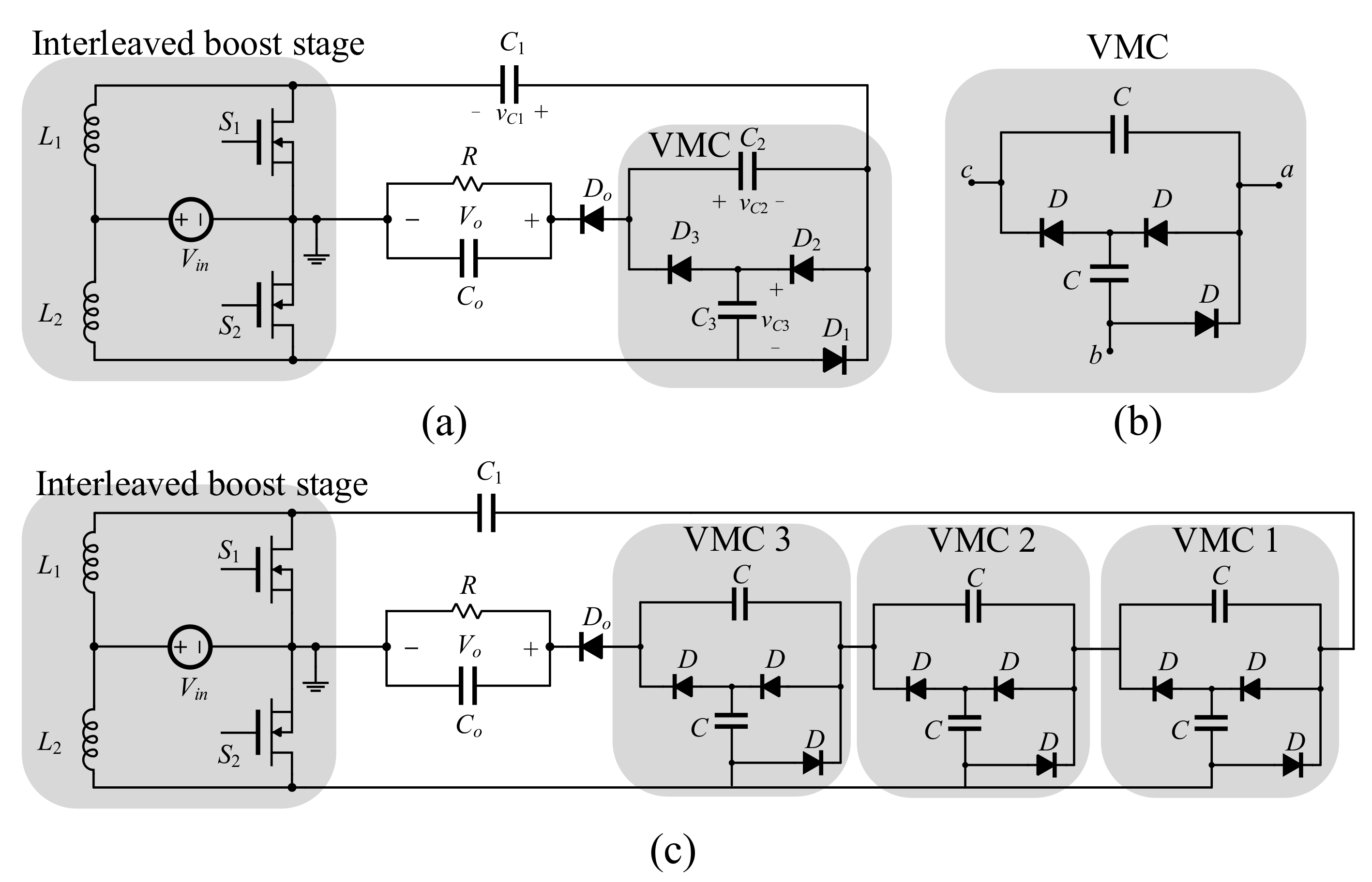
Figure 2.
Switching patterns of the MOSFETs. The converter consists of three modes of operation.

Figure 3.
The equivalent circuit during (a) interval 1; (b) interval 2; (c) interval 3.

Figure 4.
The static gain ratio of the proposed converter at various numbers of voltage multiplier cells.
Figure 4.
The static gain ratio of the proposed converter at various numbers of voltage multiplier cells.

Figure 5.
The proposed converter with two independent input sources. Both sources share the ground with the output.
Figure 5.
The proposed converter with two independent input sources. Both sources share the ground with the output.

Figure 6.
The difference in inductors’ conduction power loss between a two-phase interleaved boost where the input current is equally shared between inductors and another where input current is not equally shared between inductors.
Figure 6.
The difference in inductors’ conduction power loss between a two-phase interleaved boost where the input current is equally shared between inductors and another where input current is not equally shared between inductors.

Figure 7.
Simulation results of the inductor voltages and currents. The input current is equally shared between inductors.
Figure 7.
Simulation results of the inductor voltages and currents. The input current is equally shared between inductors.

Figure 8.
Simulation results of the voltage across the switching devices.

Figure 9.
Simulation results of the current of the MOSFETs and diodes.

Figure 10.
Simulation results of the current of the capacitors.

Figure 11.
Simulation results of he voltage across capacitors.

Figure 12.
Breakdown loss of the components as function of power (top) and breakdown percentage as a function of time (bottom).
Figure 12.
Breakdown loss of the components as function of power (top) and breakdown percentage as a function of time (bottom).

Figure 13.
The hardware prototype and experimental setup.

Figure 14.
The experimental results. Switching signals and voltage across semiconductor switches.

Figure 15.
The experimental results. Voltage across capacitors, voltage ripples, and the output voltage.
Figure 15.
The experimental results. Voltage across capacitors, voltage ripples, and the output voltage.

Figure 16.
The experimental results. Inductor currents and MOSFETs current waveforms.


Table 1.
Load voltage corresponding to different cases.
| Case | The Output Voltage |
|---|---|
| and | |
| and | |
| and | |
| and |
Table 2.
Comparison of the proposed converter with the existing topologies.
| Topology | Conventional Boost | Interleaved Boost | [33] | [34] | [35] | Proposed |
|---|---|---|---|---|---|---|
| MOSFETs | 1 | 2 | 2 | 1 | 2 | 2 |
| Capacitors | 1 | 1 | 1 | 3 | 5 | 4 |
| Inductors | 1 | 2 | 2 | 4 | 2 | 2 |
| Diodes | 1 | 2 | 3 | 8 | 5 | 4 |
| max voltage stress on MOSFETs | ||||||
| max voltage stress on Diodes | ||||||
| Equal current sharing | - | yes | - | - | No | Yes |
| Gain |
Table 3.
Parameters listing for the simulation.
| Parameter | Value |
|---|---|
| Number of voltage multiplier stages | 1 |
| 20 V | |
| 400 V | |
| Load R | 800 Ω |
| Duty cycle | 0.8 |
| 50 kHz | |
| Inductors and | 100 µH |
| Capacitors | 10 µF |
| Output capacitor | 20 µF |
Table 4.
List of elements used in the experimental prototype.
| Element | Symbol | Rating | Element # |
|---|---|---|---|
| Coils | 100 µH, DCR = 25 mΩ | 60B104C | |
| Capacitors | 10 µF | B32674D3106K | |
| MOSFETs | 150.0 V, 37.0 A = 10.53 mΩ | IPA105N15N3 | |
| Diodes | 250 V, 40 A = 0.860 V, = 0.035 µs | MBR40250G | |
| Load | various values | ceramic resistors |
Publisher’s Note: MDPI stays neutral with regard to jurisdictional claims in published maps and institutional affiliations. |
© 2020 by the author. Licensee MDPI, Basel, Switzerland. This article is an open access article distributed under the terms and conditions of the Creative Commons Attribution (CC BY) license (http://creativecommons.org/licenses/by/4.0/).
Share and Cite
MDPI and ACS Style
Alzahrani, A. A Hybrid DC–DC Quadrupler Boost Converter for Photovoltaic Panels Integration into a DC Distribution System. Electronics 2020, 9, 1965. https://doi.org/10.3390/electronics9111965
AMA Style
Alzahrani A. A Hybrid DC–DC Quadrupler Boost Converter for Photovoltaic Panels Integration into a DC Distribution System. Electronics. 2020; 9(11):1965. https://doi.org/10.3390/electronics9111965
Chicago/Turabian StyleAlzahrani, Ahmad. 2020. "A Hybrid DC–DC Quadrupler Boost Converter for Photovoltaic Panels Integration into a DC Distribution System" Electronics 9, no. 11: 1965. https://doi.org/10.3390/electronics9111965
Note that from the first issue of 2016, this journal uses article numbers instead of page numbers. See further details here.