Article

Design and Optimization of Coupling Coils for Bidirectional Wireless Charging System of Unmanned Aerial Vehicle

Tianjin Key Laboratory of Advanced Electrical Engineering and Energy Technology, Tiangong University, Tianjin 300387, China
*
Author to whom correspondence should be addressed.
Electronics 2020, 9(11), 1964; https://doi.org/10.3390/electronics9111964
Submission received: 29 September 2020 / Revised: 13 November 2020 / Accepted: 19 November 2020 / Published: 20 November 2020
(This article belongs to the Special Issue Wireless Power Transfer and Its Applications)

Abstract

:
To solve the battery power supply problem with wireless sensor networks (WSNs), a novel bidirectional wireless charging system is proposed, in which an unmanned aerial vehicle (UAV) can fly to the WSNs to charge sensors through high-frequency wireless power transfer (WPT) and also obtain energy for its own battery in the same way. To improve the performance of the UAV bidirectional wireless charging system, a lightweight design is adopted to increase its loading capacity and working time. Moreover, the radii and the numbers of turns and pitches of coupling coils were designed and optimized on the basis of simulations and experiments. Experimental results show that the weight of optimized UAV coil was reduced by 34.45%. The power transfer efficiency (PTE) of the UAV coil to sensor coil increased from 60.2% to 74.4% at a transmission distance of 15 cm, while that of the ground transmitting coil to UAV coil increased from 65.2% to 90.1% at 10 cm.

1. Introduction

Wireless sensor networks (WSNs) are an important part of Internet of things (IoT), which has been widely applied in environmental monitoring, biomedical observation, agricultural production, and industrial production [1,2,3,4]. Most WSNs are battery-powered. If the battery is not replaced on time, the energy of the sensors will be insufficient, causing interruption of the network. Therefore, the costs of this method are higher, and the reliability of WSNs is poor [5]. In practice, it is difficult for sensors to obtain energy by replacing their batteries, because some areas cannot be reached directly by people, such as high-voltage areas and those inside equipment. As a result, the development of WSNs is restrained. To solve the above problems, some researchers tried using natural energies such as bioelectricity, sunlight, wind, and vibration to power WSNs [6,7,8,9]. Although only a few mWs of energy are needed to make the sensor work, in some enclosed structures such as mineshafts and inside buildings, power will have to be supplied remotely when there is no source of ambient energy at the location of the sensor node [10].
To solve the power supply problem with WSNs in complex environments without reducing the performance of sensors, wireless power transfer (WPT) technology has become an effective method [11,12]. As mobile robot technology has matured further, WPT technology now allows mobile chargers to transfer power to sensor nodes wirelessly without requiring accurate localization of the sensor nodes or strict alignment between the charger and nodes [13]. In [11,14,15,16], vehicles traveled inside WSNs and charged sensors wirelessly using WPT technology. However, in some complex environments such as mountains, water, or bridges, vehicles may not reach the sensor nodes quickly and easily [17,18,19].
As a good mobile carrier, unmanned aerial vehicles (UAVs) can work in any environment. Combined with WPT technology, WSNs can be charged wirelessly by the UAV, thus extending the network lifetime [18]. A UAV-assisted microwave WPT system was proposed in [19], in which a UAV with a microwave launcher was designed to charge WSNs at a transmission distance of 30 cm. Nevertheless, the energy conversion efficiency was not high, and the human nervous system was affected by microwaves [20]. In [21,22], methods for charging sensors on a bridge using UAVs were put forward. However, the radii of coils were more than 25 cm, and the sensor coils were arranged inconveniently, which seriously affected the UAV’s working time.
Up to now, the power supply problem with UAV batteries still has not been solved. Meanwhile, the lightweight design of a WPT device on the UAV side and miniaturization of the coupling coil on the sensor side have not been taken into account. From this aspect, we propose a novel UAV bidirectional wireless charging system for WSNs. High-frequency magnetic coupling resonance WPT technology is rarely used in UAVs. It can achieve longer-distance power transmission without using ferrite and other magnetic materials, which can better reduce the weight of the system [23]. The remainder of this paper is organized as follows: Section 2 introduces the bidirectional wireless charging system using a UAV. In Section 3, the influences of coil parameters on the power transfer efficiency (PTE) and transmission distance are simulated and analyzed. In Section 4, experiments based on WPT are described, thereby verifying the effect of coil parameters. Finally, conclusions are given in Section 5.

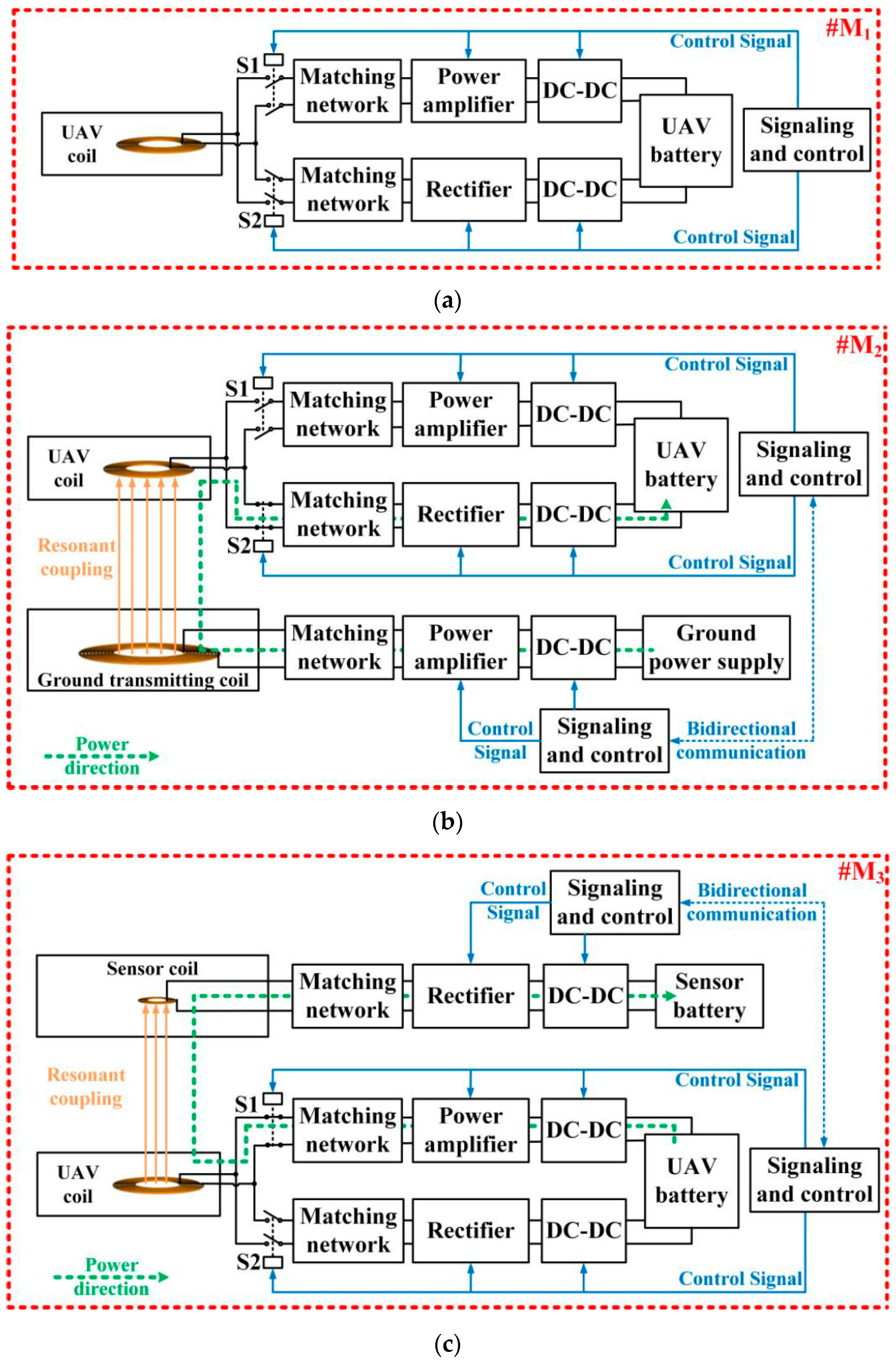
2. Bidirectional Wireless Charging System of UAV

Figure 1 shows the working modes of a bidirectional wireless charging system, which consists of the ground transmitting side, UAV side, and sensor side. The power can be transferred from the ground transmitting side to the UAV via WPT, as well as from the UAV to sensors.
As shown in Figure 1, the UAV is composed of three working modes. When the UAV battery does not need to be charged, the power request is not sent from the sensor; thus, the UAV works in a standby state, called working mode 1 (#M1). When the UAV battery needs to be charged, the UAV flies to the ground transmitting side and is wirelessly charged. This is a power receiving state, i.e., working mode 2 (#M2). When the UAV battery is fully charged, the power request is sent from the sensor that is wirelessly charged by the UAV flying to the specified position. At this moment, the UAV works in a power transmitting state, i.e., working mode 3 (#M3).
Figure 2 shows the bidirectional wireless charging system of the UAV.
As shown in Figure 2a, when switches S1 and S2 are turned off, the system is in #M1, and the power of the UAV battery is not transmitted or received.
As shown in Figure 2b, when S1 is turned off and S2 is closed, the system is in #M2, and power is received by the UAV. Direct current (DC) is provided by the ground power supply, which is transformed into alternating current (AC) by the DC-DC and power amplifier modules. A high-frequency magnetic field is generated at the ground transmitting coil, inducing current through the UAV coil. Note that this current can be provided for the UAV battery through rectification and DC-DC modules. The power flow direction is shown by the green dotted line.
As shown in Figure 2c, when S1 is closed and S2 is turned off, the system is in #M3, and power is transmitted by the UAV. DC is provided by the UAV battery, which is transformed into AC by the DC-DC and power amplifier modules. A high-frequency magnetic field is generated at the UAV coil and further induces current through the sensor coil. Note that this current can be provided for the sensor battery through rectification and DC-DC modules. The power flow direction is shown by the green dotted line.
In order to realize a lightweight design of the UAV WPT system, the transmitting and receiving coils on the UAV side are set to be identical. Since the transmitting and receiving functions are realized by one coil, the PTE and transmission distance of the WPT system must be considered in two working modes. At the same time, the weight of the UAV coil and the size of the sensor coil should also be taken into account.
According to the principle of equivalent circuit, the two WPT systems in the bidirectional wireless charging system are similar. As a result, this system can be unified into an asymmetric structure. Figure 3 shows the model of the WPT system and its equivalent circuit.
The system model is shown in Figure 3a, where the high-frequency AC is provided by the radiofrequency (RF) power source, and the magnetic field is generated at the Tx coil. The power is received by the Rx coil wirelessly, which is further rectified to make the DC load work. The equivalent circuit is shown in Figure 3b, where the Tx coil is modeled by self-inductance L1, parasitic resistance R1, and equivalent capacitance C1, while the Rx coil is modeled by L2, R2, and C2. R0 and RL are the resistance of the power source and load, respectively. The mutual inductance M between Tx and Rx coils can be described by the following formula [24]:
M = μ 0 π N 1 N 2 r 1 2 r 2 2 2 ( r 1 2 + r 2 2 + d 2 ) 3 / 2 ,
where μ0 is permeability of a vacuum, N1 and N2 are the number of turns in the coils, r1 and r2 are the coil radii, and d is the distance between two coils. When the currents in the Tx and Rx coils are I1 and I2, respectively, and the system frequency ω = 2πf, the equivalent resistance on the primary and secondary sides can be expressed by R11 and R22 as follows:
{ R 11 = R 0 + R 1 + j ( ω L 1 1 ω C 1 ) R 22 = R L + R 2 + j ( ω L 2 1 ω C 2 ) .
The Kirchhoff law for such a system can be written as
{ U S = I 1 ( R 11 j ω M ) + ( I 1 I 2 ) j ω M 0 = I 2 ( R 22 j ω M ) + ( I 2 I 1 ) j ω M .
In the wireless charging system, the received power can reach the level of 100 W. This is greater than the consumed power of a sensor node (less than 1 W). Therefore, the power is always sufficient. In this paper, the power is not the focus, as the efficiency was selected as the main research object. According to Equation (3), the system efficiency can be defined as
η = ω 2 M 2 R L ( R 11 R 22 + ( ω M ) 2 ) R 22 .
From the above formula, the main factors affecting the system efficiency are coil impedance, mutual inductance, system frequency, etc., which are all related to coils. Therefore, the coupling coil is the most important part for the WPT system. As one of the main influencing factors, PTE can be determined as a measurement standard. However, the relationship between PTE and coil parameters cannot be obtained only from formulas. To further study the influences of coil parameters on the performance of WPT, we carried out simulations and experiments.

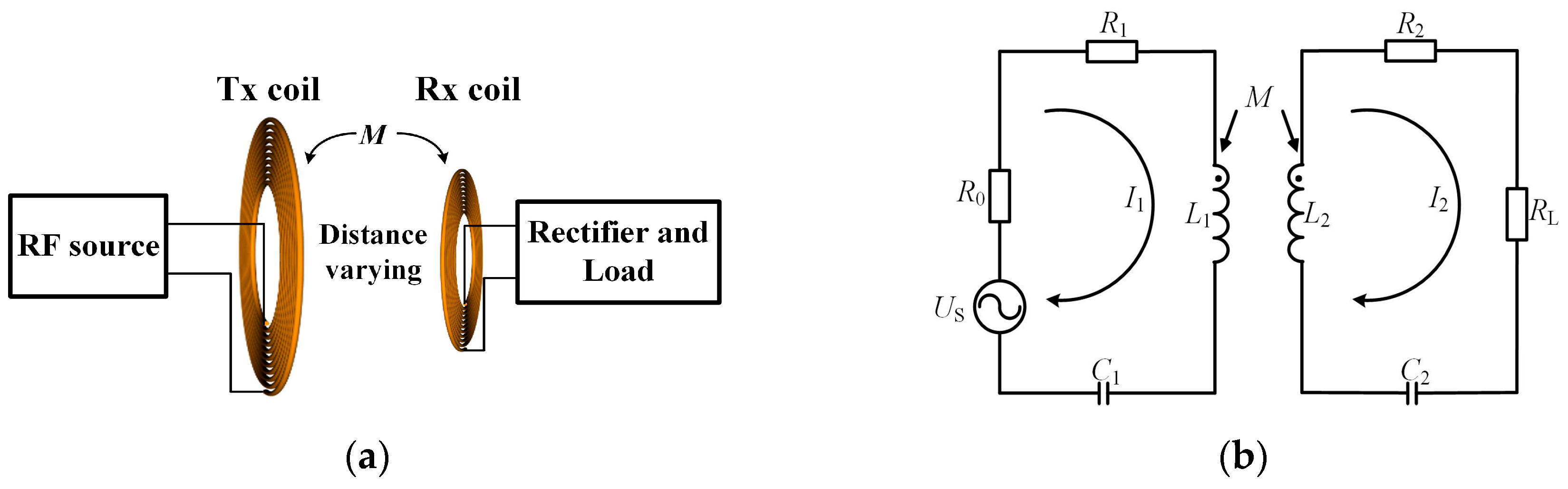
3. Design and Optimization of Coupling Coils

In the system, a small UAV was chosen. In #M2, it moved and worked within a distance of 5 to 10 cm. In #M3, its distance range was 5–15 cm, and other coil parameters are unknown. First, the influences of coil radii, the number of turns (n), and the number of pitches (p) on PTE were simulated. Then, the coil parameters were determined and further optimized.
Figure 4a shows the simulation model of a WPT system, where A is the Tx coil and B is the Rx coil. Figure 4b shows that the magnetic field distribution around two coils is visually represented by the section and magnetic induction line. In the simulations, the system frequency was 6.78 MHz, the power supply was 24 V, the load impedance was 50 Ω, and the coil shape was spiral planar. Among the coil parameters, only the wire diameter was fixed at 0.5 mm, while Tx coil radius RA, Rx coil radius RB, n, and p were set as variables.
Considering that the lightweight and miniaturized design of coil is mostly affected by the coil radius, the coil radius was studied at first, followed by the determination of coil size. Then, n and p were further optimized.

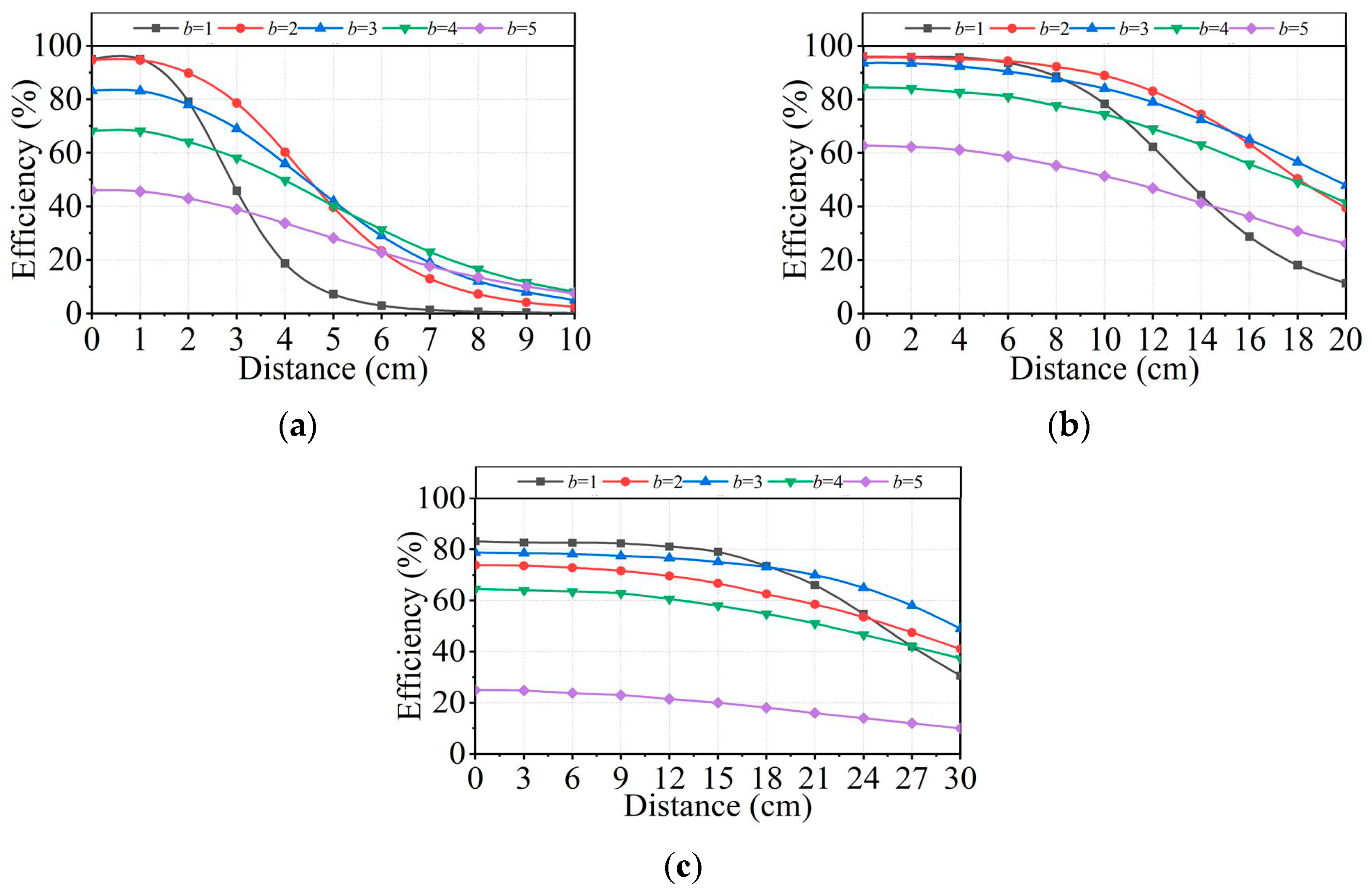
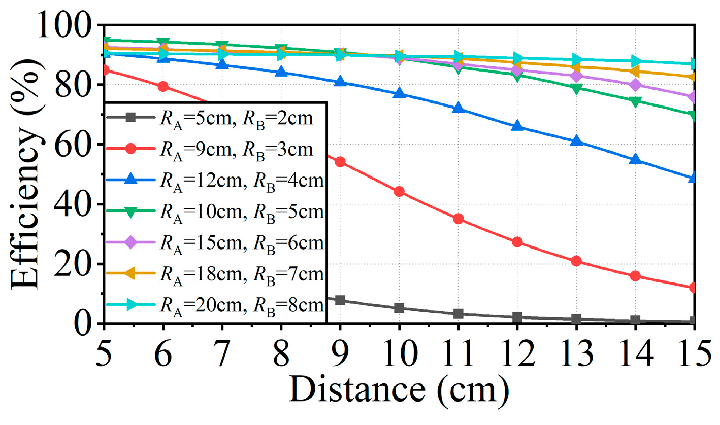
3.1. Desgin and Optimization of Coil Radius

The performance of WPT can be comprehensively expressed by the PTE and the transmission distance. As the distance increases, PTE varies in terms of its maximum efficiency and downward trend. To determine the influence of coil radius on WPT, RA and RB were set as variables, while the other parameters were set as fixed values. In the simulations, n was set to 10 and p was set to 0. The PTEs with different coil radii could be obtained, as shown in Figure 5.
As shown in Figure 5a, when RB was fixed and RA increased, the maximum efficiencies were 95.1%, 94.7%, 68.2%, 26.1%, 3.8%, 2.1%, and 1.2%. When the transmission distance was changed from 0 to 10 cm, the PTEs were reduced by 94.9%, 92.2%, 60.1%, 20.4%, 2.2%, 1.1%, and 0.5%. It can be seen that the downward trend of efficiency was weakened. When the RA was not much bigger than RB, the maximum efficiency was basically maintained. When RA increased much more quickly than RB, the maximum efficiency decreased rapidly. Similar results can be observed in Figure 5b,c.
From the above simulations, it can be seen that, although the downward trend of efficiency became slower as RA increased, the maximum efficiency decreased more quickly. Therefore, the turning point of the maximum efficiency needs to be determined. Here, the ratio of RA to RB was defined as b. In the simulations, only b varied while the other parameters remained unchanged. The corresponding results are shown in Figure 6.
Note that the simulation results shown in Figure 6 are basically consistent with those shown in Figure 5. In sum, when RB was fixed while RA was set to 1–3 times RB, the maximum efficiency changed within a small range. Therefore, b should be less than 3 when designing the coil radius.
In this paper, the working distance between the UAV and the sensor was 5–15 cm. According to the above results, when RB was around 5cm, the PTE and downward trend of efficiency were better. Therefore, RB was set to 2–8 cm in the simulation. It was also necessary to determine the best Tx coil for different Rx coils within the working distance range. First, RB was set to 2 cm, and RA was set to 2, 3, 4, 5, and 6 cm according to the criterion that b should be less than 3. Then, the transmission distance was changed from 5 to 15 cm. The simulation results of PTE with different values of RA are shown in Figure 7.
As shown in Figure 7, the maximum efficiency was the highest when RA was set to 5 cm, together with a more stable trend. Therefore, when RB was 2 cm, RA was selected as 5 cm to ensure the best PTE. In the same way, PTE varied with the coil combinations, as shown in Figure 8.
As shown in Figure 8, when RB was less than 5 cm, the PTE decreased significantly. When RB was larger than 5 cm, the maximum efficiency and PTE did not increase significantly. Considering the design goal of sensor coil miniaturization and light weight of the UAV coil, the sensor coil radius was determined as 5 cm and the UAV coil radius as 10 cm. Through the same method, the ground transmitting side coil radius was 12 cm.

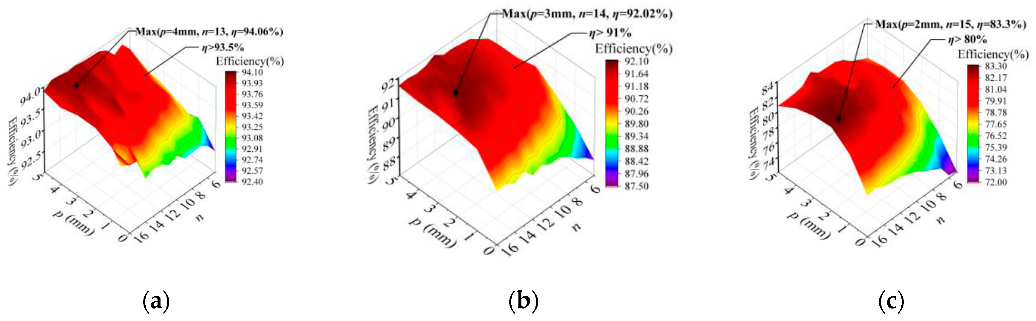
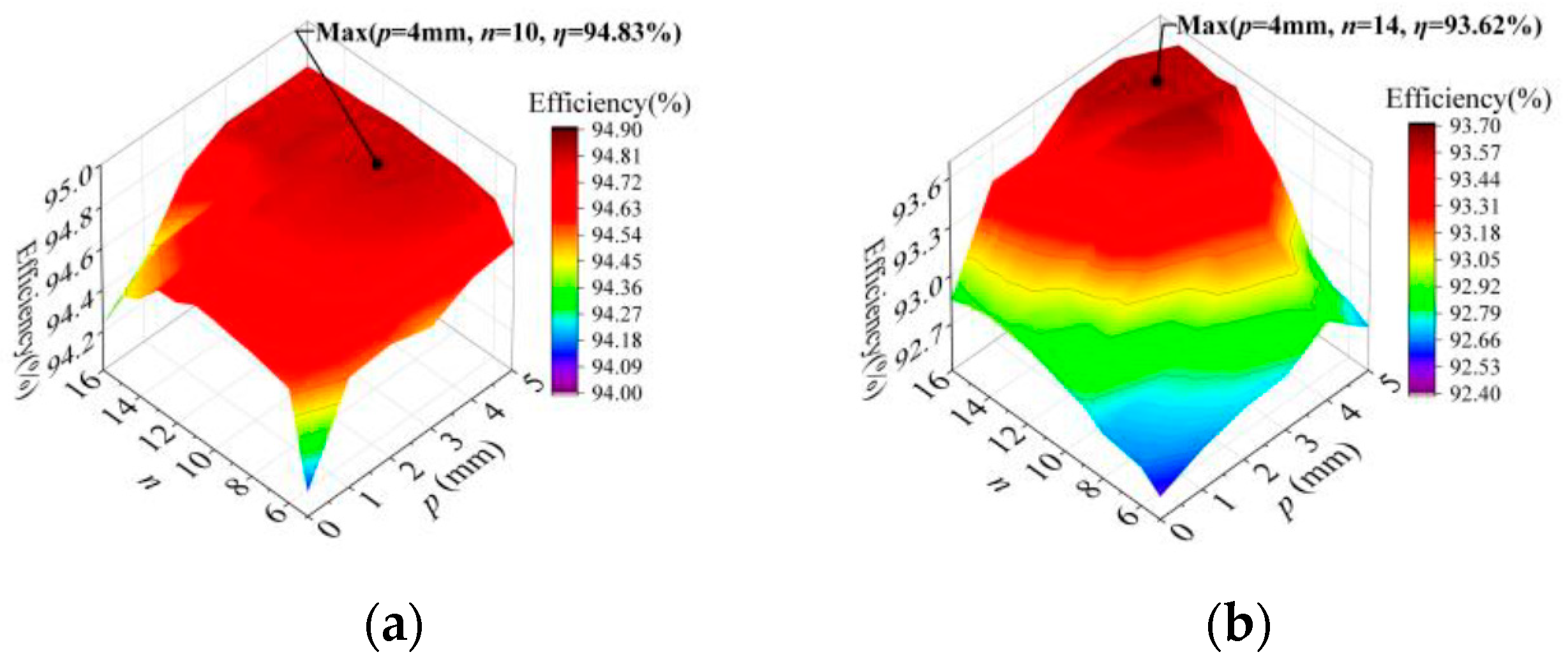
3.2. Design and Optimization of Coil Turns and Pitches

In this section, the sensor coil was used as the Rx coil and the UAV coil was used as the Tx coil in #M3. Therefore, the parameters of the Tx coil were unchanged. In the simulations, RA was set to 10 cm, and the values of n and p for Tx coil were set to 10 and 0, respectively. RB was set to 5 cm, the values of n for the Rx coil were set from 5 to 16, and the values of p for the Rx coil were set from 0 to 5 mm. Because the working distance in #M3 is 5–15 cm and the UAV would move within the working distance, transmission distances (5, 10, and 15 cm) could be used as the reference distances. The PTE study of the reference distance could be characterized as the working distance. The simulation results are shown in Figure 9.
Figure 9 shows the efficiency of sensor coils with different n and p at different distance. PTEs were represented by contour lines and different colors, while the ranges of the highest efficiency point and higher efficiency area could be clearly obtained. Considering that the miniaturization design of the sensor coil is related to the radius, not the values of n and p, only PTE needs to be compared. To make a comprehensive comparison, the three highest points were substituted into the simulation model with the transmission distance varying in the entire working distance range, as shown in Figure 10.
As shown in Figure 10, when n was 15 and p was 1 mm, the downward trend of efficiency was the slowest. In the working distance range, the PTE of this coil was the most stable, and the efficiency at the farthest distance is the highest, i.e., 76%. Therefore, p = 1 mm and n = 15 could be determined as the optimal result for the sensor coil.
The UAV coil could be optimized using the same method. In the simulations, the parameters of the Rx coil were kept the same, while those of the Tx coil were changed. RB was set to 5 cm, while the values of n and p for Rx coil were set to 15 and 1 mm, respectively. RA was set to 10 cm, the values of n for Tx coil were set from 5 to 16, and the values of p for Tx coil were set from 0 to 5 mm. The transmission distances of 5, 10, and 15 cm were still used as a reference. Considering that the lightweight design of the UAV coil is related to n and p, the coil weight and PTE need to be compared at the same time. Figure 11 shows the simulation results of PTE at different distances, where the areas with higher PTEs are marked.
As shown in Figure 11, the intersection of higher-PTE areas could be obtained, where the PTE at 15 cm characterized the performance of WPT within the entire working distance. To consider the influences of PTE and coil weight at the same time, a new contrast method was used, in which the ratio of PTE to coil weight (ηg) was defined as the unit weight efficiency. Figure 12 shows the ηg curve with different coil parameter combinations within the intersection.
As shown in Figure 12, when p was 4 mm and n was 7, the unit weight efficiency of the coil was 3.18, showing that the coil weight was lighter and the PTE within the working distance was higher. As a result, this combination could be determined as the optimal result for the UAV coil.
Lastly, the optimization method on the ground transmitting side was the same as that on the sensor side. The ground transmitting coil was used as the Tx coil, and the UAV coil was used as the Rx coil in #M2. Therefore, the parameters of the Rx coil were unchanged. In the simulations, RB was set to 10 cm, while the values of n and p for Rx coil were set to 7 and 4 mm, respectively. RA was set to 12 cm, the values of n for Tx coil were set from 5 to 16, and the values of p for Tx coil were set from 0 to 5 mm. The transmission distances of 5 and 10 cm could be used as the reference, because the working distance in #M2 was 5–10 cm. Considering that the efficient design of the ground transmitting coil is unrelated to n and p, only PTE needs to be compared. Figure 13 shows the simulation results of PTE at different distances, and the highest PTE points are marked.
The two highest points in Figure 13 were substituted into the simulation model. The transmission distance was changed within the entire working distance, and the corresponding results are shown in Figure 14.
As shown in Figure 14, when n was 4 and p was 4 mm, the PTE of the ground transmitting coil was the highest. Therefore, this combination could be determined as the optimal result.
From the above simulations, the optimal parameters could be determined for the sensor coil (radius of coil = 5 cm, n = 15, and s = 1 mm), the UAV coil (radius of coil = 10 cm, n = 7, and p = 4 mm), and the ground transmitting coil (radius of coil = 12 cm, n = 14, and p = 4 mm). In addition, the simulation results of PTE with unoptimized and optimized coils were compared, as shown in Figure 15, indicating that the optimization effect of the coils was obvious.

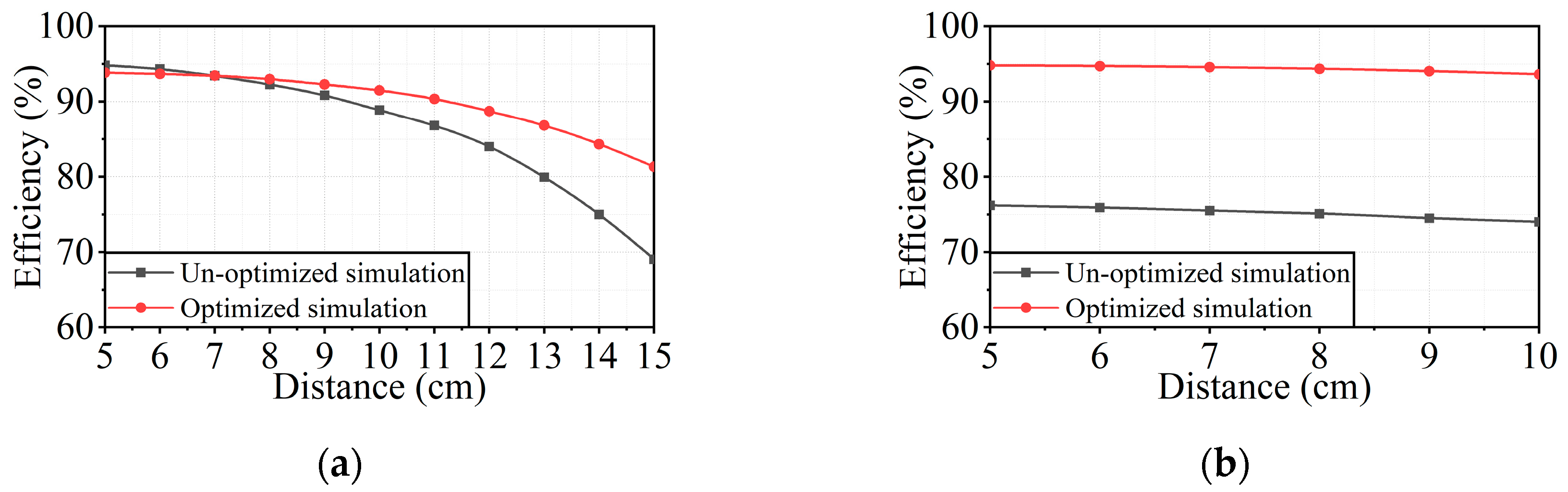
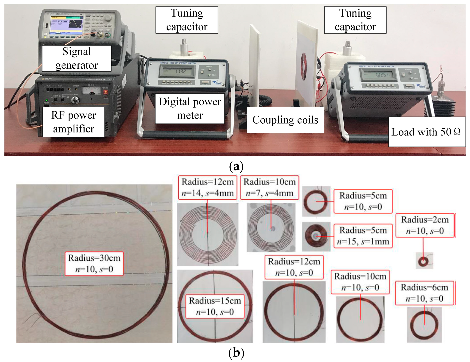
4. Experimental Results

As shown in Figure 16a, an experimental platform was built on the basis of the simulations to verify the influences of coil radius and the number of turns and pitches on the performance of WPT system. In Figure 16b, the planar spiral coils with different parameters are shown.
At first, the influences of coil radii on WPT were verified. In this experiment, the value of n for coils was 10 and that of p was 0. The coils with radii of 6, 15, and 30 cm were selected as Tx coils, and those with radii of 2, 5, and 10 cm were selected as Rx coils. The experimental and simulation results are shown in Figure 17.
As shown in Figure 17, the PTE attenuation trends in the experimental and simulation results were consistent, also verifying that the radius ratio b should be less than 3.
Then, the optimization effect of n and p was measured. The coils in Table 1 were selected as the unoptimized and optimized sensor coils, UAV coils, and ground transmitting coils. The WPT experiments results are shown in Figure 18.
As shown in Figure 18a, the PTE was reduced by 25.75% and 12.53% in the simulation, with respect to 31.82% and 18.55% in the experiment. The experimental results showed that the downward trend of efficiency weakened. As shown in Figure 18b, the maximum efficiencies increased by 18.61% and 22.12% in the simulation and experiment. This shows that the maximum PTE of the optimized UAV and ground transmitting coils was significantly improved. The experimental results were consistent with the simulation results. Next, the received power was measured. In the sensor and UAV system, 3–15.8 W could be received by the unoptimized sensor coil, while the optimized coil received 6.8–22.2 W. In the UAV and ground transmitting side system, 8.8 to 34.4 W could be received by the unoptimized UAV coil, while the optimized coil could receive 10.9–41.2 W. It can be seen that the received power would be sufficient for the sensor and UAV battery.
At the same time, the weight of the UAV coil was measured. The weight of the unoptimized coil was 44.7 g, while that of the optimized coil was 29.3 g. Compared with the unoptimized coil, the weight of the optimized coil was reduced by 34.45%. Experimental results proved that both the size and the weight of coils could be effectively reduced, and the PTE could be effectively improved through coil optimization. Therefore, the optimized coils meet the requirements for a bidirectional wireless charging system in all aspects.

5. Conclusions

In this paper, a bidirectional wireless charging system of UAV was proposed to solve the power supply problem with WSNs. The conclusions are summarized as follows:
  • The power can be wirelessly transferred to the UAV battery from the ground power supply, as well as to the sensor battery from the UAV battery.
  • A smaller Rx coil and a larger Tx coil should be used, but the radius ratio of Tx to Rx coils should not be more than 3.
  • The optimal parameters were determined for the sensor coil (radius = 5 cm, n = 15, p = 1 mm), the UAV coil (radius = 10 cm, n = 7, p = 4 mm), and the ground transmitting coil (radius = 12 cm, n = 14, p = 4 mm).
  • Through the optimization of coil parameters, the weight of the coil was reduced by 34.45% experimentally. At the same time, the PTE of the optimized UAV to sensor coils increased by 22% at a transmission distance of 15 cm, and that of the optimized ground transmitting side to UAV sensors increased by 25.1% at 10 cm.

Author Contributions

The paper was written by Y.L., X.N., Y.Z., and Y.H. and revised by R.W., J.L., and J.M. The project was conceptualized, planned, and supervised by Y.L. All authors have read and agreed to the published version of the manuscript.

Funding

This research was funded by the National Natural Science Foundation of China under Grant 51877151, Grant 51577133, and Grant 51677132, and in part by the Program for Innovative Research Team in University of Tianjin under Grant TD13-5040.

Conflicts of Interest

The authors declare no conflict of interest.

References

  1. García, L.; Parra, L.; Jimenez, J.M.; Lloret, J.; Lorenz, P. IoT-Based Smart Irrigation Systems: An Overview on the Recent Trends on Sensors and IoT Systems for Irrigation in Precision Agriculture. Sensors 2020, 20, 1042. [Google Scholar] [CrossRef] [PubMed] [Green Version]
  2. Wenning, B.-L.; Pesch, D.; Timm-Giel, A.; Görg, C. Environmental monitoring aware routing: Making environmental sensor networks more robust. Telecommun. Syst. 2009, 43, 3–11. [Google Scholar] [CrossRef]
  3. Ansari, A.A.; Gera, P.; Mishra, B.; Mishra, D. A secure authentication framework for WSN-based safety monitoring in coal mines. Sadhana 2020, 45, 1–16. [Google Scholar] [CrossRef]
  4. Sheeja, R.; Sutha, J. Soft fuzzy computing to medical image compression in wireless sensor network-based tele medicine system. Multimedia Tools Appl. 2019, 79, 10215–10232. [Google Scholar] [CrossRef]
  5. Tong, B.; Wang, G.; Zhang, W.; Wang, C. Node Reclamation and Replacement for Long-Lived Sensor Networks. IEEE Trans. Parallel Distrib. Syst. 2011, 22, 1550–1563. [Google Scholar] [CrossRef]
  6. Deng, F.; Yue, X.; Fan, X.; Guan, S.; Xu, Y.; Chen, J. Multisource Energy Harvesting System for a Wireless Sensor Network Node in the Field Environment. IEEE Internet Things J. 2018, 6, 918–927. [Google Scholar] [CrossRef]
  7. Sharma, H.; Haque, A.; Jaffery, Z.A. Maximization of wireless sensor network lifetime using solar energy harvesting for smart agriculture monitoring. Ad Hoc Netw. 2019, 94. [Google Scholar] [CrossRef]
  8. Qian, J.; Jing, X. Wind-driven hybridized triboelectric-electromagnetic nanogenerator and solar cell as a sustainable power unit for self-powered natural disaster monitoring sensor networks. Nano Energy 2018, 52, 78–87. [Google Scholar] [CrossRef]
  9. Chamanian, S.; Baghaee, S.; Ulusan, H.; Zorlu, O.; Uysal-Biyikoglu, E.; Kulah, H. Implementation of Energy-Neutral Operation on Vibration Energy Harvesting WSN. IEEE Sens. J. 2019, 19, 3092–3099. [Google Scholar] [CrossRef]
  10. Percy, S.; Knight, C.; Cooray, F.; Smart, K. Supplying the Power Requirements to a Sensor Network Using Radio Frequency Power Transfer. Sensors 2012, 12, 8571–8585. [Google Scholar] [CrossRef] [Green Version]
  11. Xie, L.; Shi, Y.; Hou, Y.T.; Lou, A. Wireless power transfer and applications to sensor networks. IEEE Wirel. Commun. 2013, 20, 140–145. [Google Scholar] [CrossRef]
  12. La Rosa, R.; Dehollain, C.; Livreri, P. Advanced Monitoring Systems Based on Battery-Less Asset Tracking Modules Energized through RF Wireless Power Transfer. Sensors 2020, 20, 3020. [Google Scholar] [CrossRef] [PubMed]
  13. Peng, Y.; Li, Z.; Zhang, W.; Qiao, D. Prolonging Sensor Network Lifetime Through Wireless Charging. In Proceedings of the 2010 31st IEEE Real-Time Systems Symposium, San Diego, CA, USA, 30 November–3 December 2010; pp. 129–139. [Google Scholar]
  14. Shi, Y.; Xie, L.; Hou, Y.T.; Sherali, H.D. On renewable sensor networks with wireless energy transfer. In Proceedings of the 2011 IEEE INFOCOM, Shanghai, China, 10–15 April 2011; pp. 1350–1358. [Google Scholar]
  15. Xie, L.; Shi, Y.; Hou, Y.T.; Lou, W.; Sherali, H.D.; Midkiff, S.F. On renewable sensor networks with wireless energy transfer: The multi-node case. In Proceedings of the 2012 9th Annual IEEE Communications Society Conference on Sensor, Mesh and Ad Hoc Communications and Networks (SECON), Seoul, Korea, 18–21 June 2012. [Google Scholar]
  16. Xie, L.; Shi, Y.; Hou, Y.T.; Sherali, H.D. Making Sensor Networks Immortal: An Energy-Renewal Approach With Wireless Power Transfer. IEEE/ACM Trans. Netw. 2012, 20, 1748–1761. [Google Scholar] [CrossRef]
  17. Suman, S.; Kumar, S.; De, S. UAV-Assisted RF Energy Transfer. In Proceedings of the 2018 IEEE International Conference on Communications (ICC), Kansas City, MO, USA, 20–24 May 2018; Institute of Electrical and Electronics Engineers (IEEE): Piscataway, NJ, USA; pp. 1–6. [Google Scholar]
  18. Basha, E.; Eiskamp, M.; Johnson, J.; Detweiler, C. UAV Recharging Opportunities and Policies for Sensor Networks. Int. J. Distrib. Sens. Netw. 2015, 11, 8. [Google Scholar] [CrossRef]
  19. Shigeta, R.; Suzuki, K.; Okuya, F.; Kawahara, Y. Trilateration-Inspired Sensor Node Position Estimation for UAV-Assisted Microwave Wireless Power Transfer. SICE J. Control. Meas. Syst. Integr. 2017, 10, 350–359. [Google Scholar] [CrossRef]
  20. D’Andrea, J.A.; Chou, C.-K.; Johnston, S.A.; Adair, E.R. Microwave effects on the nervous system. Bioelectromagn. 2003, 24, S107–S147. [Google Scholar] [CrossRef] [PubMed]
  21. Johnson, J.; Basha, E.; Detweiler, C. Charge selection algorithms for maximizing sensor network life with UAV-based limited wireless recharging. In Proceedings of the 2013 IEEE Eighth International Conference on Intelligent Sensors, Melbourne, VIC, Australia, 2–5 April 2013; pp. 159–164. [Google Scholar]
  22. Griffin, B.; Detweiler, C. Resonant wireless power transfer to ground sensors from a UAV. In Proceedings of the IEEE International Conference on Robotics & Automation, Saint Paul, MN, USA, 14–18 May 2012; pp. 2660–2665. [Google Scholar]
  23. Jawad, A.M.; Nordin, R.; Gharghan, S.K.; Jawad, H.M.; Ismail, M. Opportunities and Challenges for Near-Field Wireless Power Transfer: A Review. Energies 2017, 10, 1022. [Google Scholar] [CrossRef]
  24. Bieler, T.; Perrottet, M.; Nguyen, V.; Perriard, Y. Contactless power and information transmission. IEEE Trans. Ind. Appl. 2002, 38, 1266–1272. [Google Scholar] [CrossRef]
Figure 1. Working modes (a) #M2 and (b) #M3 of bidirectional wireless charging system.
Electronics 09 01964 g001
Figure 2. Unmanned aerial vehicle (UAV) bidirectional wireless charging system in working modes (a) #M1, (b) #M2, and (c) #M3.
Electronics 09 01964 g002
Figure 3. (a) Mode and (b) equivalent circuit of wireless power transfer (WPT) system.
Electronics 09 01964 g003
Figure 4. (a) Simulation model and (b) magnetic field model of WPT system.
Electronics 09 01964 g004
Figure 5. Power transfer efficiency (PTE) curves with different coil radii: (a) RA = 2–24 cm, RB = 2 cm; (b) RA = 2–24 cm, RB = 5 cm; (c) RA = 2–24 cm, RB = 10 cm.
Electronics 09 01964 g005
Figure 6. PTE curves with different values of b: (a) RA = 2–10 cm, RB = 2 cm; (b) RA = 5–25 cm, RB = 5 cm; (c) RA = 10–50 cm, RB = 10 cm.
Electronics 09 01964 g006
Figure 7. PTE curves with different values of RA.
Electronics 09 01964 g007
Figure 8. PTE curves with different coil combinations.
Electronics 09 01964 g008
Figure 9. PTE of sensor coil with different values of n and p, at distances of (a) 5 cm, (b) 10 cm, and (c) 15 cm.
Electronics 09 01964 g009
Figure 10. PTE curves with different coil parameters.
Electronics 09 01964 g010
Figure 11. PTE of UAV coil with different values of n and p, at distances of (a) 5 cm, (b) 10 cm, and (c) 15 cm.
Electronics 09 01964 g011
Figure 12. Unit weight efficiency with different coil parameters.
Electronics 09 01964 g012
Figure 13. PTE of ground transmitting coil with different values of n and p, at distances of (a) 5 cm and (b) 10 cm.
Electronics 09 01964 g013
Figure 14. PTE curves with different coil parameters.
Electronics 09 01964 g014
Figure 15. PTE curves with unoptimized and optimized coils: (a) UAV to sensor; (b) ground transmitting side to UAV.
Electronics 09 01964 g015
Figure 16. (a) Experimental platform; (b) coils with different parameters.
Electronics 09 01964 g016
Figure 17. PTE curves with different coil radii.
Electronics 09 01964 g017
Figure 18. Comparison between simulation and experimental results: (a) UAV to sensor; (b) ground transmitting side to UAV.
Electronics 09 01964 g018
Table 1. Unoptimized and optimized coil parameters.
Coil TypeRadius (cm)Pitch (mm)Number of turnsTuning Capacitor (pF)
UnoptimizedSensor501038.5
UAV100109.35
Ground120105.04
OptimizedSensor511530.84
UAV104733.4
Ground1241410.1
Publisher’s Note: MDPI stays neutral with regard to jurisdictional claims in published maps and institutional affiliations.

