A Review on Biopolymer-Based Fibers via Electrospinning and Solution Blowing and Their Applications


1
School of Engineering, Indian Institute of Technology Mandi, Mandi HP-175005, India
2
Department of Mechanical and Industrial Engineering, University of Illinois at Chicago, Chicago, IL 60607-7022, USA
*
Author to whom correspondence should be addressed.
Fibers 2018, 6(3), 45; https://doi.org/10.3390/fib6030045
Submission received: 18 April 2018
/
Revised: 24 May 2018
/
Accepted: 8 June 2018
/
Published: 2 July 2018
(This article belongs to the Special Issue Biopolymer Nanofiber)
Abstract
:Electrospinning, for the last few decades, has been extensively acknowledged for its ability to manufacture a macro/nanofibrous architecture from biopolymers, which is otherwise difficult to obtain, in a cost effective and user-friendly technique. Such biopolymer nanofibers can be tailored to meet applications such as drug delivery, tissue engineering, filtration, fuel cell, and food packaging etc. Due to their structural uniqueness, chemical and mechanical stability, functionality, super-high surface area-to-volume ratio, and one-dimensional orientation, electrospun biopolymer nanofibers have been proven to be extremely beneficial. A parallel method in nonwoven methodologies called “Solution Blowing” has also become a potential candidate to fabricate a similar type of architecture from biopolymer fibers, and is gaining popularity among researchers, despite its recent advent in early 2000’s. This review chiefly focuses on the fabrication of biopolymer macro/nanofibers via electrospinning and solution blowing, and several applications of such fiber architectures. Biopolymers include plant- and animal-derived biopolymers, such as cellulose, lignin, chitin, and chitosan, as well as proteins and their derivatives. The fabrication of biopolymer fibers from these biopolymers alone or as blends, predominantly with biodegradable polymers like Polyvinyl alcohol (PVA), Polyethylene Oxide (PEO), Polyethylene glycol (PEG), poly (lactide-co-glycolide) (PLGA) etc., or non-biodegradable polymers like polyamide, Polyacrylonitrile (PAN) etc., will be discussed in detail, along with the applications of several composites of such sort.
1. Introduction
In the last several decades, there has been an impetus on development of sustainable and eco-friendly products to reduce dependency on fossil fuels. Apart from a boost in the renewable energy sector, like the rapid growth of photovoltaics, the urgency of removal of petroleum-derived plastic from the eco-system has accelerated wide research on bio-friendly polymers, aka biopolymers. Biopolymers are derived from natural and/or plant-based materials, like bio-waste, forest feed hoard (including wood and its wastes), residues, horticulture, crops and their by-products. They are now finding their day to day applications, especially polymers which are biodegradable or based on renewable “feedstock”, which may soon compete with commodity plastics. This prediction is entirely based on the sales growth of bio-friendly polymers, which is as high as 20–30% per year [1]. A report by Transparency Market Research predicts the overall growth of biopolymer based industries to expand at an impressive rate of 14% between 2017 and 2025, where the market share of such industries will increase from USD 2422 million in 2016 to USD 7775 million by 2025. This report predicted such massive growth on the basis of applications of various bio-derived polymers, for example Polyethylene terepthalate (PET), bio-Polyethylene (PE), biodegradable Polyester, Polylactic acid (PLA) etc. In the present market valuation and future prediction, Europe shares the biggest portion, largely due to the mass awareness and strict norms. However, Asia-pacific is also becoming a major share-holder in this industry, due to their massive market. The major biopolymers from plant-derived sources are cellulose and lignin, or polymers chemically synthesized from plant-derived monomers like PLA, from animal sources such as chitosan, or from microorganism sources like polyhydroxyalkanoates (PHA). Even proteins, carbohydrates, DNA, and RNA etc. are finding their applications widely in biopolymer-derived composites for specialized applications, like drug delivery, tissue engineering, wound healing etc., for such composites’ antibacterial, antifungal, and antiviral activities and, moreover, on their biodegradability and biocompatibility [2]. Over the years, many researchers have explored biopolymer composites for various applications, for instance (ligno)-cellulose microfibril reinforcement for the betterment of mechanical properties of plasticized starch matrix [3], 5–7 nm thick platelet-like starch nanocrystals as reinforcement in a waxy maize starch matrix which has been plasticized with glycerol [4], nanobio-composite of thermoplastic material from wheat with PLA [5], calcium cross-linked alginate, photo cross-linked alginate, collagen hydrogels for siRNA delivery [6], and porous scaffold made from thermally induced phase separation of Chitosan and alginate polymers [7] etc.
Along with these forms of composites, nonwoven and woven nanofiber and microfiber architecture of biopolymers fabricated by either Electrospinning [8], Solution Blowing [9], or a combination of these, known as blowing assisted electro-spinning [10] or alternatively electro-blowing [11], Wet Spinning [12], or Self-assembly [13] have gained attention amongst researchers because of their wide application, namely-air filtration [14], protective clothing [15], drug delivery carrier [16], liquid filtration [17], substitutes for agricultural pesticides [18], and nanocomposites, micro- and nanoelectronic devices [19], electrostatic dissipation [20] etc. for their unique morphology, one-dimensional orientation of individual nanofibers, large porosity, and increased tortuosity. Close attention to Figure 1 will elucidate the fact that despite the focused and massive research that has been conducted on biopolymers over the years (1996–2017), only a small fraction was carried out with biopolymer micro/nanofibers. The comparison in Figure 1 shows the difference of annual scientific publications over the world, comparing biopolymers and biopolymer fibers, obtained from Web of Science search system (24 March 2018) where the keywords were chosen as abovementioned, and particularly for journals the word “biopolymer” was emphasized.
It is very important to know that the fabrication of biopolymer fibers is not straightforward and not as scalable as synthetic polymers or thermoplastic polymers, which can be extruded into fibers via melt blowing or wet-laid processes. Biopolymers at higher temperatures can denaturalize [21]. Often, the only possible routes for making biopolymer fibers are via non-thermal processes, which involve polymer solutions like solution blowing or electrospinning. However, depending on various parameters, such as molecular weight, degree of deacetylation (for chitosan), purity of the polymers, distribution of charges or charged groups etc., the solvent selection becomes critical, and so are the process parameters like flow rate, voltage applied for electrospinning, air flow rate, and ambient temperature for solution blowing [22,23].
In the scope of this article, a systematic review is conducted on the researches and developments, in conjunction with polymer fibers from some of the abundant biopolymers from natural and animal sources, their morphologies, and most importantly their applications. Other issues with technological limitations and research challenges will also be addressed, along with the abovementioned discussions. This review will first address the brief description of methodologies of fabrication of polymer fibers, namely electrospinning and solution blowing, and the dependencies of process parameters in fabrication. An elaborate review on electrospinning of several biopolymers will be discussed next, based on individual biopolymers with different subsections, followed by a detailed description on solution blown biopolymer fibers, albeit the process of solution blowing is relatively new but has great potential for industrial scalability. Afterwards, several applications of biopolymer fibers will be discussed.
2. Fabrication of Polymer Fibers: Electrospinning and Solution Blowing
There are various methods available for the fabrication of polymer micro- and nanofibers, namely melt blowing [24,25], electrospinning [26,27,28,29,30,31,32], solution blowing [33,34,35,36,37,38], self-assembly [39], phase separation [40], island in the sea [41], drawing [42], template synthesis, wet spinning, dry spinning, and melt spinning [13,43]. Although the individual fabrication method has its own advantages, electrospinning is the most popular one, because of its relative simplicity and scalability to produce fibers from 1 μm–100 nm reproducibly [44,45,46]. Solution blowing, a process kindred to melt blowing, is the most industrially explored technique for large-scale fabrication of nanofibers without major alteration of textile practices, and has a similar production rate to the latter method [47].
2.1. Electrospinning
The idea of electrospinning or “electrostatic spinning” dates back to 1934 [48,49,50], where, in a series of patents, the fabrication of polymer filaments using electrostatic force was demonstrated. After years of evolution, electrospinning has become one of the major nanotechnological processes, where polymer fibers of the scale of 1 μm–10 nm can be produced on a mass scale [51,52,53,54,55]. Donaldson Inc. was one of the forerunners in using electrospun nanofibrous media in dust filtration during the late 1980s [56], which suggested the obvious industrial scale fabrication and its immense potential across various domains [57,58,59,60]. Electrospinning was picked by academia in the 1990s because of the prominent work done by Reneker and co-workers, and to date more than 18,000 journal articles have been published on electrospinning (Data obtained from Web of Science on 24 March 2018, with keyword search “Electrospinning”). Electrospinning differs from the conventional wet/dry fiber spinning or melt blowing on a basic aspect of driving potential, as in the latter cases aerodynamic drag is the responsible force, whereas in the former one electrostatic attraction drives the process. The absolute fiber diameter largely differs from conventional fiber spinning processes where fibers are mostly of several microns in diameter and in electrospinning, fibers are in the scale of 100 nm. An electrospinning setup has three major components, as shown in Figure 2a—(I) a high voltage DC power supply; (II) a spinneret or die (a metallic capillary tip, generally a needle); and (III) a collector (a grounded conductor), static or rotating. In a characteristic procedure (see Figure 2a), a syringe filled with polymer solution is pumped using a syringe pump to produce a stable flow of solution through needle/spinneret. This needle is connected to a high voltage source that generates an electrostatic field between needle/spinneret and collector (in this case a rotating drum collector) that acts as the ground, where the spinneret to collector distance generally varies between 10–30 cm. The applied high voltage varies between 6–30 kV. Upon application of high DC potential, the solution becomes highly charged and subsequently, the solution droplet at the tip of the spinneret experiences two major forces—(a) the electrostatic repulsion force and (b) surface tension. Due to the high electrostatic potential, the solution droplet acquires a conical shape at the tip of syringe with a definite half angle [the half angle was measured to be 49.3° referred as the Taylor Cone, a seminal work on electrically driven liquid jets conducted by Sir Geoffrey Taylor in 1969 [61] which was later modified as 33.5° by Yarin et al., (2001) [62]. Beyond a critical voltage, the repulsive force of the charged polymer overcomes the surface tension of the solution. A charged polymer jet gets ejected in a straight path from the tip of the Taylor Cone, which moves toward the collector. Shortly after, in flight, the jet experiences perturbations and consequently three bending instabilities (first followed by second, third, or higher [63,64,65]), more like “Whipping” and spiraling. As the jet proceeds to the collector, the solvent evaporates (or the melt solidifies for melt spinning) as the jet gets thinner and solid fibers get deposited as a randomly oriented nonwoven mat (c.f. Figure 2b) after experiencing stretching of the order of 105 S−1, which is otherwise difficult to achieve in conventional fiber drawing processes [63,66,67].
Electrospinning as a process is rather simple, however the physics behind is complex, as the entirety of the process is dependent on multiple governing parameters that are characteristic to polymer solution, namely solution viscosity, polymer concentration, solution conductivity, and surface tension. Many researchers have tried to extrinsically change parameters that affect the overall spinning, such as reducing surface tension by adding surfactants [68], and adding NaCl to increase PEO spinnability [69]. However, drawing a single conclusion from such additions is difficult. The process parameters are also important to take note of, namely applied voltage, spinneret to collector distance, relative humidity, temperature, and flow rate. Hartman et al., (2000) [70] has shown that diameter of charged polymer jet (D) was related to the feed rate (Q) following , which was driven by the bending instability of charged jets. Excessive spinneret to collector distance can affect the fiber in three ways—(a) increase diameter, due to polymer macromolecules’ relaxation, as suggested by Li et al., (2004) [71]; (b) decrease diameter, solvent had more time to evaporate before reaching to the collector [72]; and (c) beaded fiber [73]. Humidity and temperature both dictate the evaporation rate and thus can be deemed to be a crucial parameter for uniform fiber diameter [74]. However, for biological substances like enzymes, co-flowing with polymer solution, high temperatures can be detrimental.
2.2. Solution Blowing
To date, melt blowing is the most important commercial technique amongst nonwoven methodologies for fabrication of polymer microfibers. In this process, a molten polymer is pumped through a fine capillary and then rapidly drawn into fibers, aided by high-velocity hot gas flow that comes out co-axially with the polymer melt. The fibers get collected on an open screen and form a nonwoven web [46,74]. However, this method is suitable for polymers like polypropylene, polyester, polyamide, polyurethane, thermoplastic elastomers, polyethylene etc. and not strictly for biopolymers, as they tend to denaturalize at high temperature. Recently, a nonwoven fabrication method called Solution Blowing has come into practice, in which a polymer solution is extruded and not polymer melt. This gives an excellent opportunity to maneuver the final composite, especially with biopolymer blends.
Isothermal subsonic blowing of polymer solutions as a method of forming monolithic fibers was introduced by Medeiros et al., (2009) [75] and Sinha-Ray et al., (2010) [33]. Solution blowing is kindred to melt blowing; the only difference lies in solvent evaporation in the former, rather than melt cooling jet solidification in the latter, and solution blowing is basically an isothermal method. Unlike melt blowing, which produces microfibers, solution blowing results in nanofibers [74,76,77]. Figure 3 represents a schematic view of solution blowing. The key components in solution blowing are—(a) well designed co-axial die, with core nozzle for polymer solution flow and shell nozzle for high speed air flow (see Figure 3b); and (b) high speed air-supply. The feed rate of the polymer solution via a single nozzle can be as high as 10 mL/h, as described by Kolbasov et al., (2015) [47]. Air flow is generally of the order of 150–200 m/s at 3–5 bar of pressure. The accelerated gas jet stretches the core polymer jet, which after passing through a brief ~1 mm straight part, with massive diameter reduction experiences substantial bending instability with stretching, more like flapping in the surrounding air [78,79,80,81]. Meanwhile, the solvent evaporates and the polymer jet solidifies in the form of fiber and gets collected on a solid grid or drum collector. The biggest advantage of solution blowing, apart from its ability to blend biopolymers, is its scalability, almost at par with melt blowing, as demonstrated by Kolbasov et al., (2015) [47]. In this paper, authors have also demonstrated industrial scale solution blowing with PEO and Clarisoy (Soy protein isolate) where, with 328 nozzles of 0.002 inch I.D., authors prepared nonwoven samples in the range of 900–1600 cm2 in 10 s with solid weight of 5.1 g and fiber diameters varying between 0.5–1.5 μm. Several other authors, like Oliveira et al., (2013) [82], and Guan et al., (2011) [28] also have demonstrated the feasibility of this process with polymers like PLA and PEO; the latter being known for its spinnability, and even with thermoplastic polymer like Polyurethane (PU). Solution blowing depends on various parameters, namely nozzle dimensions, air pressure, collecting distance, and viscoelasticity of the polymer solution [47,74].
It is already established that solution blowing facilitates production of nonwoven like melt blowing, but, like electrospinning, it also allows to blend additives and most importantly the biopolymers, a detail of which will be discussed later. The work done by Kolbasov et al., (2015) [47] was a classic example of the above statement, as authors had demonstrated solution blowing of soy-protein based fibers, which they had collaborated with BIAX-Fiber film Inc., in laboratory scale solution blown nanofiber mats containing chitosan, lignin, sodium alginate, zein etc. have already been explored. which only shows the prospect of this method for fabrication towards “green” plastic [47,83]. From the advent of this process so far, ~200 scientific journals have been published, which only indicates to the scope of this method to be researched more in depth (Data collected from Web of Science with Keywords search ‘solution blowing’ and ‘fibers’). Unlike electrospinning, not many articles are available that actually detail the factors that affect the solution blowing process. However, in several articles [47,79] the possibility of “fly” and “shots” formation have been discussed, due to uneven drying of polymer jet in air for improper die design. The nozzle selection for solution blowing based on the viscoelasticity of the solution is also critical, and to avoid capillary instability incurred in the polymer jet followed by bead formation, air speed should be increased [47]. A similar effect was observed by [84], where fiber diameter was decreased with an increase in air pressure, albeit a reverse relation was seen between temperature and fiber diameter. The parametric effect of collector screen velocity in the narrowing of fiber diameters is less in solution blowing [79], unlike in electrospinning [85] or melt blowing [74], however it indeed affects the overall porosity of the architecture and the mass distribution of the lay down [86].
Blowing assisted electro-spinning [10] or electro-blowing [11] are essentially similar techniques, a combination of solution blowing and electrospinning. In this method, the die serving as the solution blowing nozzle is connected to a high voltage power supply, whereas the ground is the collector. Apart from aerodynamic stretching, the electrostatic force allows additional thinning of the polymer jets. Sometimes this additional stretching can be important to overcome high viscoelasticity of the polymer, and the stretching of polymer jet can be tuned by tweaking the air flow rate, feed rate, and air temperature, similar to solution blowing [10]. This method can be useful for large-scale synthesis of biopolymer fibers tailored for applications in wound healing, tissue engineering, etc. A similar method was also introduced by Sinha-ray et al., (2010) [33] where core-shell nanofibers were fabricated using a similar method to ultimately fabricate hollow carbon nanofibers, where the core was poly-methylmethaacrylate (PMMA) and shell was PAN. Although the method is seemingly attractive, not much work has been done in the field of biopolymers using this said technology. Hence, this review will not focus on this particular methodology and will largely describe electrospinning and solution blowing.
3. Fabrication of Biopolymer Fibers via Electrospinning
In this section, fabrication of micro/nanofibers from several biopolymers like cellulose, chitosan, lignin, and several proteins and protein isolates or their derivatives will be discussed, either as sole biopolymers or their blends with another carrier polymer. Most of the studies conducted using biopolymer micro/nanofibers, fabrication to application, have focused on electrospinning, and only a handful studies have been conducted with solution blowing. Hence, to keep a fair parity throughout this review, impetus will be largely on electrospinning of the abovementioned biopolymers. The next subsection, thus, will elaborate on several biopolymers and fabrication of fibers from them using electrospinning. However, in the later section, solution blown biopolymers will be also discussed, but in an aggregated form.
When it comes to biopolymer and/or bio-waste based polymer electrospinning, it is very important to realize that there will be lot of complications while spinning. The spinning of polysaccharides, such as cellulose, or animal-derived biopolymers, like chitosan, and charged polymers, like protein, DNA, and RNA, is extensively complicated [87], compared to the electrospinning of synthetic polymers [88]. Compared to neutral biopolymers, charged biopolymers face long-range electrostatic interaction because of the presence of counter ions [89,90], which inhibits preferred electrospinning in charged ones.
3.1. Cellulose
Cellulose is the most available, biodegradable, renewable biopolymer. It is also one of the most researched biopolymers, either pure or in derivative form. Cellulose belongs to the class of poly-dispersed linear-chain biopolymer with poly-b(1,4)-d-glucose units having asyndiotatic configuration (c.f. Figure 4).
Cellulose and its ester derivatives, like-Cellulose acetate (CA), cellulose acetate phthalate (CAP), Cellulose acetate butyrate (CAB),Cellulose acetate trimelitate (CAT), Hydroxupropylmethyl cellulose phthalate (HPMCP), and its ether derivatives like Methyl cellulose (MC), Ethyl cellulose (EC), Hydroxyethyl cellulose (HEC), Hydroxypropyl cellulose (HPC), Hydroxypropylmethylcellulose (HPMC), Carboxymethyl cellulose (CMC), and Sodium carboxymethyl cellulose (NaCMC) etc. [79,91] are very hard to process, yet they have found their way in numerous industrial applications, such as textiles, papers, plastics, and food packaging [92]. Cellulose doesn’t dissolve in common solvents because of strong intra-molecular hydrogen bonds, but it dissolves in dimethylsulfoxide/paraformaldehyde and sulfur dioxide etc. [93,94,95,96]. These solvents are not suitable for electrospinning applications, as during the process solvents evaporate and hence researchers mostly use the ether and ester based cellulose derivatives for electrospinning, albeit compromising cellulose’s ability of delayed degradation and structural stability [97,98,99].
At the very onset of electrospinning in 1934, derivatives of cellulose, cellulose acetate, and propionyl cellulose were electrospun with pure acetone and alcohol mixed with 1 g of Solactol and Palatinol (softening agents) [100]. Commercial cellulosic fibers were obtained by dissolvingα-cellulose in a 50% water solution of N-methylmorpholine N-oxide (NMMO) solvent, with 1 wt. % antioxidant, which can break its intra-molecular hydrogen bonds easily [93]. The electrospinning was conducted at 80–100 °C and fibers were electrospun on a coagulation bath. The electrospun fibers, as mentioned in [93], ranged between 200–400 nm, some with a spaghetti-like structure (c.f. Figure 5b). In the same year (2005), cellulose was electrospun using a different solvent mixture-lithium chloride (LiCl) and N,N-dimethylacetamide (DMAc), and it was reported that the presence of lithium chloride, and no other salt, is necessary to bridge the electrostatic interaction between DMAc and cellulose. This process was found appropriate, and it was concluded that using this solvent with 3% cellulose concentration, stable and dry nanofibers could be collected, and later by using bath coagulation, lithium chloride was totally removed [101]. The nanofibers were collected at 100 °C, with only 4% of molecular weight loss. The authors predicted that these nanofibers have great potential for further applications in filtration studies.
Several other authors have also reported the solubility of cellulose in LiCl/DMAc solvent mixture at various concentrations, however, solution preparation with NMMO/H2O system is challenging and often requires high temperature with complicated system requisites [102,103,104,105,106]. Both the solvent systems are proven to be useful cellulose nanofiber, although, preparation using LiCl/DMAc often lead to amorphous nanofibers and using NMMO/H2O leads to varying degrees of crystallinity [107].
3.1.1. Derivatives of Cellulose: Cellulose Acetate
Cellulose acetate (CA) is the most used derivative of cellulose and commonly used in filtrations (like ultra-filtrations and reverse osmosis), and in biomedical applications for its biocompatibility [108]. Cellulose, acetic acid, and acetic anhydride are mixed together and reacted to form CA. This process is aided by the addition of a small amount of sulfuric acid, which is subsequently neutralized during processing.
CA possesses weak intra-molecular hydrogen bonds as compared to cellulose, and solvents used for cellulose in general and at large scale are simpler than that of cellulose, such as acetone, N,N-dimethylformamide (DMF), Tetrahydrofuran (THF) etc. either alone or their mixture, although Liu et al., (2002) [43] has reported fabrication of CA nanofiber using electrospinning of CA: NMMO/H2O system. The solubility of CA in polar solvents can be affected by to the variation of number of acetyl groups per anhydro-glucose unit (increased hydroxyl content) [109,110]. CA solution in acetone generates some complications while performing electrospinning, because it leads to bead formation, possibly due to solidification by freezing of polymer and low boiling point of acetone, as demonstrated by Jaeger et al., (1998) [111]. The effect of acetone can be mitigated by using acetone/(DMAc) solvent system to obtain stable nanofiber morphology and consistent nanofiber diameter between 100 nm to 1 μm, although it depends upon both solution and process parameters, like viscoelasticity, spinneret to collector distance, etc. [112]. In 2003, Son et al., (2004a) [96] used an acetone/H2O solvent system to fabricate CA nanofibers of 460 nm under basic pH conditions. Ultra-fine cellulose fibers were regenerated following homogeneous deacetylation from the abovementioned CA fibers in KOH/ethanol solvent mixture (c.f. Figure 6). The said reaction was followed a pseudo-first order reaction given by:
where, [C] is the concentration of acetate groups at any time, t, and [C]0 is the original concentration of acetate groups at the first time, t0, and k is the rate constant. The activation energy evaluated for the deacetylation of ultra-fine CA was found to be 10.3 kcal/mol from Arrhenious equation.
The same authors, in a separate work, used a mixture of solvents containing HNO3/H3PO4-NaNO2 and HNO3/H2SO4-NaNO2 on the deacytalized cellulose nanofibers to oxidize them. Upon oxidizing the nanofibers, less crystallinity was observed, due to disturbance of hydrogen bonds between cellulose chains. However, upon using the former solvents, the nanofibers swelled, but nonwoven architecture remained uninterrupted, but using the latter the nanofiber morphology was completely ruptured, as can be seen by the images in Figure 7a,b. This work was motivated to attain possible applications in nonwoven adhesion barriers, in cosmetic and pharmaceutical preparations, fibrin formation-accelerating agents etc. [113,114,115]. In a separate work conducted by Liu et al., (2002) [112], cellulose acetate was electrospun into continuous nanofibers using acetone and DMAc solvent mixture (2:1). These CA nanofibers were consequently hydrolyzed to regenerate the hydroxyl groups, finally to obtain cellulose nanofibers.
Tungprapa et al., (2007b) [116] studied the effects of various parameters on the architecture of CA fiber mats, namely solvent system, solution concentration, and applied electrical potential. The solutions for electrospinning CA were prepared in two solvent systems—(a) single, like acetone, chloroform, DMF, dichloromethane (DCM), methanol (MeOH), formic acid (FA), and pyridine; and (b) mixed, like acetone-DMAc, chloroform-MeOH, and DCM-MeOH. It was suggested that the smooth fibers can be achieved from 16% (w/v) CA solution in 1:1, 2:1, and 3:1 (v/v) acetone-DMAc, 14–20% (w/v) CA solutions in 2:1 (v/v) acetone-DMAc, and 8–12% (w/v) CA solution in 4:1 (v/v) DCM-MeOH. Electrospinning of CA in an acetic acid (AA): water solvent system (3:1 by weight) was carried out by Han et al., (2008) [117]. The authors had shown that electrospun CA fiber of mean diameter 180 nm could be fabricated from a 17 wt. % CA solution and the fiber diameter could be controlled with the applied potential. CA and PEO bi-component fibers by electrospinning of binary mixtures of these polymers was achieved by Zhang et al., (2008) [118], where it was seen that the threshold MW of CA and PEO for smooth electrospinning of 20 wt. % solutions in DMF were 50 kDa and 100 kDa, respectively. However, addition of a low dielectric solvent dioxane mixed with DMF in equal proportions helped the fiber formation from CA only without PEO. In an independent work done by Taepaiboon et al., (2007) [119], 16 w/v % CA was electrospun with 0.5 wt. % vitamin A and 5 wt. % vitamin E for cosmetic applications. The diameters of these electrospun nanofibers were in range 247 nm to 265 nm, and over a long period of testing these nanofibers released vitamins monotonously, following a Fickian profile with time dependency of order 0.5 as compared to burst release from vitamin loaded CA films.
A number of articles with various processing technique involving CA macro/nanofibers are available because of its importance. Apart from the abovementioned noteworthy articles, there are several articles that have listed important processing conditions for fabrication of CA nanofibers, either via solo polymer-solvent system, or via CA/carrier polymer-single/multi solvent-salt/additive systems. In Table 1, a comprehensive list of several processing conditions of CA fibers is presented, along with some other cellulose derivatives.
3.1.2. Derivatives of Cellulose: Ethyl Cellulose, Hydroxypropyl Cellulose etc.
Apart from CA, Ethyl cellulose, Hydroxypropyl cellulose, Hydroxypropyl methylcellulose are the other most researched cellulose derivatives which have been used in micro/nanofiber fabrication. In the year 2004, ethyl-cyanoethylcellulose was first electrospun from EC and acrylonitrile in tetrahydrofuran, and about 200 nm of porous nanofibers were obtained [127,128,129,130]. The CECs have recently found applications in low-voltage organic field-effect transistors (OFETs) [131]. EC was electrospun using solvent system tetrahydrofuran/DMAc by Wu et al., (2004) [132], and was tested at different solvent ratios. Li et al., (2013) [133] demonstrated Ketoprofen (KET) (an anti-inflammatory)-loaded EC electrospinning, using ethanol as solvent. Second-order interactions, like hydrogen bonding, electrostatic interactions, and hydrophobic interactions boost compatibility between KET and EC which played instrumental role in sustained drug release. Another abundant cellulosic derivative is hydroxypropyl cellulose, which was electrospun using two different solvents with different electrospinning parameters, such as high voltage, tip to collector distance, collection speed, feed rate, etc. The nanofiber mats obtained were used in MEMS devices by converting them into network of nano- and micro-porous tin oxide [126].
3.2. Chitin and Chitosan
3.2.1. Chitin
Chitin and chitosan are cellulose equivalents with a (1,4)-b-N-acetyl glycosaminoglycan repeating structure and its deacetylate derivative, respectively [48]. Chitin chemical structure is near similar as shown in Figure 4, with a slight difference of the organic group, R = NHAc for chitin instead of R = OH for cellulose. Chitin is the most available animal-derived biopolymer found mainly in the exoskeletons of crabs, shrimps, prawn, and insects, and the cell wall of mushrooms [134]. The annual production of chitin is 1010–1011 tons; however, it is mostly thrown away in the fishery industries. A detailed report on chitin fiber extraction from crab shells was provided by Ifuku et al., (2009) [48] where small flakes of crab shell were first treated by with NaOH and HCl to obtain 1% pure chitin which was further followed by mechanical grinding treatment to convert chitin into nanofibers (c.f. Figure 8). The chitin nanofibers were reportedly uniform with width of 10–20 nm and high aspect ratio.
Application of chitin is somehow restricted because of its insoluble nature in the majority of organic solvents, since it is a neutrally charged polymer. Chitin is soluble in solvents like 1,1,1,3,3,3-hexafluoro-2-propanol (HFIP), hexafluoroacetone, chloroalcohols with 5% LiCl in DMAc, and mineral acids in aqueous solution, because of its extensive inter and intramolecular hydrogen bonds through acetamido groups and high crystallinity [20,135,136]. In the year 2004, Min et al., [137] irradiated chitin of molecular weight 91 kDa with Co60 gamma ray and later dissolved the irradiated Chitin in HFIP continuously for three days. The final concentration of chitin solution for electrospinning was in the range from 3–6 wt. %, which was conducted at high voltage of 15 kV and was collected on a drum collector. It can be seen in Figure 9 from the authors’ work that as the solution concentration was increased the nanofibers became more uniform, and at 6 wt. % an average diameter of 110 nm could be obtained. Deacetylation of Chitin nanofibers was conducted by refluxing the mat in 40% NaOH solution for 1–3 days at 60 °C, and the degree of deacetylation was found to be 85% [138].
Chitin and Other Polymer Blends
A similar work was conducted by Park et al., (2005) [139] with Chitin powder (MW = 920 kDa and degree of deacetylation ~8%) irradiated for 20 days and then mixed with HFIP. The electrospinning conditions were voltage 17 KV and spinner-to-collector distance 7 cm. Chitin/Polyglycolic acid (PGA) blend was electrospun by mixing a 5 wt. % of the former and 8 wt. % of the latter at different weight ratios (0/100, 25/75, 50/50, 75/25, and 100/0) dissolved in HFIP. Mean diameter of pure Chitin, pure PGA, Chitin/PGA (25/75), Chitin/PGA (50/50), and Chitin/PGA (75/25) were 130 nm, 380 nm, 150 nm, 140 nm, and 140 nm, respectively. The work mostly concentrated on fabrication of biodegradable and biomimetic scaffolds for tissue engineering. An in vitro degradation study revealed hydrolytic cleavage of PGA in the blend nanofibers hastened by the presence of hydrophilic chitin. The cytocompatibility and cell behavior study suggested good cell attachment on the nanofiber architecture. A similar work was carried out by the same author [140], where instead of PGA, silk fibroin (SF) was used with chitin. 5 and 7 wt. % of chitin and SF, respectively, were dissolved in HFIP and a series of chitin/SF solutions were prepared, again at different weight ratios, namely 100/0, 75/25, 50/50, 25/75, and 0/100. The polymer blends were electrospun nearly at identical spinning conditions, as mentioned previously, to obtain composite nanofibers with average diameters of 1300, 900, 600, 400, and 300 nm for Chitin/SF- 100/0, 75/25, 50/50, 25/75, and 0/100 solutions, respectively. This study also aimed at tissue engineering, in which authors reported 75/25 chitin/SF to be the best candidate among all the other nanofiber blends.
Carboxymethyl Chitin
Carboxymethyl chitin (CMC) was electrospun using PVA as the carrier polymer for tissue engineering application to avoid of any trace organic solvent, like HFIP that may remain in the nanofibers during electrospinning [141]. 7 wt. % CMC was mixed with 8 wt. % PVA solution, both in distilled water, in seven different compositions: 0/100, 20/80, 40/60, 50/50, 60/40, 80/20, and 100/0 for w/w 2 h. Electropsun nanofibers of CMC/PVA 20/80 were cross-linked with glutaraldehyde vapors for 12 h in a desiccator, followed by heating at 112 °C for 12 h. However, due to the presence of glutaraldehyde traces as toxic chemical in the unwashed scaffold material, there was a considerable decay on cell viability. In a recent work done by Li et al., (2016) [142], chitin nanofibers were extracted from speckled swimming crab shells via deproteinization, demineralization, depigmentation, and mechanical disintegration. A series of chitin/deacetylized chitin nanofibers and CMC films reinforced with nanofiber concentrations, namely 0, 1, 5, and 10 wt. %, based on CMC weight, were prepared using the solution casting method. The deacetylized chitin nanofiber/CMC samples showed better antimicrobial and mechanical properties, due to exposed amino groups at the surface with a percolating. According to authors, this has immense potential in food packaging applications.
Chitin Whiskers
Another chitin composite, α-chitin whiskers (CW) reinforced with PVA, was electrospun by Junkasem et al. [143]. α-CW were prepared from chitin flakes of shells of Penaeusmerguiens shrimps [Sea fresh Co., Ltd. (Bangkok, Thailand)] hydrolyzed in 3 N hydrochloric acid (HCl) and heated for 6 h at 120 °C. After hydrolysis, these acid-treated whiskers were then suspended in de-ionized water and later centrifuged at 1000 rpm for 10 mins. PVA solution of 10 wt. % concentration was prepared by dissolving in distilled water at 85 °C and then as prepared CWs between (1 to 10 g) were added in 20 g of PVA solution at different percentages, namely 2.55, 5.11, 7.66, 10.11, 12.76, 15.17, 17.74, and 25.38%. The mixtures were electrospun at 15 kV with 20 G needle at 45° angle and all the nanofibers were collected with a feed rate of 3mL/h, and the mean diameter of nanofibers obtained were 175, 185, 210, 216, 213, 216, 218, 216, and 214 nm for different CW wt. %, as discussed above.
3.2.2. Chitosan
Chitosan is a natural polysaccharide biopolymer obtained by deacetylation of chitin. It is obtained by co-polymerization of (1 ⟶ 4)-2-amino-2-deoxy-β-d-glucan and (1 ⟶ 4)-2-acetamido-2-deoxy-β-d-glucan [144]. Chitosan chemical structure is nearly similar to chitin and cellulose, and can be obtained just by replacing R = OH with R = NH2, as shown in Figure 4 above. Commercially available chitosan is generally 85% deacetylated, which comprises of -NH2 functional group on the repeated unit C-2 of d-glucosamine, which also renders them a better chelating agent than cellulose [145,146,147]. During deactylation, the polysaccharides are transformed into polyelectrolyte in acidic medium. It is mostly soluble acidic solvents such as AA, FA, malic acid (MA), and others, if pH is less than 6.5 [148], because at higher pH levels, polymer molecules lose their charges and may precipitate out of the solution due to deprotonation of amine (-NH2) groups. Chitosan properties in a solution generally depend on molecular weight, degree of deacetylation, charge of polymer, ionic strength, and pH [149,150,151]. Generally because of this protonation and deprotonation of the amino groups of chitosan in acidic solvents, it behaves like cationic polyelectrolyte with very high charge density.
Chitosan is mostly known for its biocompatibility, biodegradability, metal chelating, mucoadhesive and antimicrobial properties. It exhibits high mechanical strength and shows high affinity towards proteins and, because of its excellent biological activities, it can be used in a wide range of applications, such as food, biomedical, cosmetic, chemical, and pharmaceutical industries [152,153,154,155,156,157].
Geng et al., (2005) [158] reported electrospinning of chitosan nanofibers using high concentration acetic acid as a solvent. The authors electropsun 7% chitosan solution in aqueous 90% acetic acid solution at a very high electric field of 4 kV/cm and obtained nanofibers with mean diameter 130 nm. They indicated that an aqueous acetic acid concentration of more than 30% was required for chitosan nanofiber fabrication, to mitigate the effect of surface tension and consequently to increase charge density of the jet without altering viscosity. Ohkawa et al., (2004) [159] reported the production of pure chitosan nanofibers in Trifluoroacetic acid (TFA) for the first time, along with several other solvents as well. However, TFA aided in the production of nanofibers in submicron range (~490 nm) quite reproducibly by two ways: First, TFA forms salts with the amino groups of chitosan destroying the rigid backbone of chitosan molecules; and second, high volatility of TFA helps rapid solidification of the electrified polymer jet. Later, Schiffman et al., (2008) [160] demonstrated production of chitosan nanofibers from unfiltered low, medium, and high molecular weight chitosan, and also practical-grade chitosan (c.f. Figure 10). The as-spun nanofiber mats were greatly soluble in acidic and aqueous solutions, hence authors suggested cross-linking with glutaraldehyde (GA) vapor to produce insoluble nanofiber mat. However, the cross-linked mat showed poorer mechanical performance in terms of Young’s modulus and ultimate tensile strength compared to the pristine mat, due to the lessening influence of cohesive forces between fibers.
Alkali treatment of chitosan to hydrolyze chitosan chains and decrease its molecular weight for favorable electrospinning was demonstrated by Homayoni et al., (2009) [11]. Electrospinning of 7 and 7.5 wt. % of Chitosan in acetic acid concentrations of 80% and 70% led to nanofibers with mean diameters of 250 and 284 nm, respectively. This work was also one of the first works to identify means of reduction of acid concentration to electrospin chitosan fibers.
Chitosan Derivatives
Apart from electrospinning of pure chitosan fibers its derivatives, like Hexanoyl chitosan (HC) and PEG grafted chitosan (PEG-C) etc., were also attempted for electrospinning. HC was found to be anti-thrombogenic and resistant to hydrolysis incurred by lysosomes, hence an early work was conducted by Neanmark et al., (2006) [161] where the author had dissolved HC in chloroform to achieve the final concentration 4% and 14% w/v. The average fiber diameter varied between 460–930 nm, with an increment in fiber size with increase in HC concentration. PEG, a low-toxicity, biocompatible, and biodegradable polymer, is an excellent candidate for grafting, and PEG-C shows good affinity towards water or organic solvents. Electrospinning of 15% PEG-N,O chitosan from 3/1 (v/v) THF/DMF solvent mixture with 0.5% Triton X-100TM surfactant (mainly to reduce surface tension) produced uniform nanofibers of average diameter of 162 nm [162].
Chitosan/PEO Blends
As already discussed, electrospinning of pure chitosan is tricky because of its polyelectrolytic nature; several researchers blended other biodegradable polymers like PVA, PEO etc. Chitosan was electrospun with PEO at various wt. percentages in 2 wt. % aqueous acetic acid as solvent. The diameter distribution of nanofibers obtained was between 80 and 180 nm, and mean fiber size was 124 nm. However, in their study, they showed that due to phase separation of PEO and chitosan, both ultra-fine and microfibers were seen, in which microfibers contained only PEO and ultra-fine fibers contained chitosan alone [163]. Later the same year, Spasova et al., (2004) [164] successfully produced ultra-fine chitosan/PEO blended fibers and showed that with fiber diameter decreased with increasing chitosan content in a decreasing blend concentration. Higher electric field however had a negative impact on the overall diameter distribution. These nanofibers exhibited antibacterial and antimycotic activity against E. coli. Bhattarai et al., (2005) [165] explored chitosan/PEO solutions (at different ratios of chitosan and PEO in final concentration) in 0.5 M acetic acid followed by centrifugation to remove air bubbles. Such solution was later mixed with 0–0.5 wt. % of Triton X-100 TM and 0–10 wt. % DMF, and the final solution was electrospun at 20–25 kV with controlled feed rate and tilted syringe. Electrospinning of different Chitosan/PEO compositions, namely 60/40 and 90/10, produced ultra-fine nanofibers with mean diameter 38 nm and 62 nm, respectively. PEG incorporated chitosan with different PEG/Chitosan ratio 12/1, 8/1, 4/1, 2/1, 1/1, and 1/2 were prepared and electrospun to obtain ultra-fine fibers of diameter 130–150 nm. However, PEG/Chitosan with 12/1 and 8/1 ratio had bead formation along with nanofibers during electrospinning. This polymer-blended chitosan nanofibers were prone to dissolution in water almost instantly, hence cross-linking with glutaraldehyde was attempted, which could resist polymer dissolution in water up to 48 h [81].
Chitosan/PVA Blends
PVA is a non-toxic, water-soluble, biocompatible, and biodegradable synthetic polymer. It has wide applications in the biomedical domain, and it can be also spun into fibers easily. Apart from its biodegradability, PVA is highly compatible with chitosan [109]. In the same article, it was shown using FTIR that PVA blends with chitosan via strong interaction through hydrogen bonding and increases the tensile strength of chitosan. Chitosan/PVA composite membranes were fabricated by dissolving chitosan in acetic acid with 90 v/v % concentration mixed with PVA dissolved in distilled water. A 70/30 mixture of chitosan/PVA was electrospun, and later PVA was dissolved out with NaOH. The mean fiber diameters without NaOH treatment and with NaOH treatment were between 150–300 nm and 80–150 nm, respectively. The stabilized (NaOH treated) chitosan nanofibrous membrane was used for enzyme immobilization [166]. PVA chitosan composite nanofiber using water and acetic acid solvents was also discussed in [167,168] where PVA was dissolved in distilled water at 20 wt. % concentrations and 3 wt. % chitosan solution was prepared by dissolving in 2 wt. % aqueous acetic acid. Afterwards, both the solutions were mixed at different weight ratios of PVA/Chitosan: 90/10, 80/20, 75/25, and 70/30, respectively, for electrospinning. It was seen that nanofibers diameter decreased from 300 nm to 125 nm as PVA composition was decreased. Increasing PVA/Chitosan concentration from 3% to 9%, electrospun nanofibers average diameter increased from 60 nm to 420 nm. Below 3 wt. %, they observed only bead formation. In a separate work conducted by Jin et al. (2008) [127] cross-linking of PVA/chitosan nanofibers was attempted, where Polyethyleneglycol-600-dimethylacrylate (PEGDMA) and photo-initiator 2-hydroxy-1-[4-(2-hydroxyethoxy) phenyl]-2-methyl-1-propanone (HEPK) were mixed with CS/PVA blend, and then the electrospun fibers were irradiated with UV rays. The nano-cross-linked fibers ranged between 200–800 nm. Recently in 2018, Das et al. [169] fabricated PVA/Chitosan nanofibers by electrospinning, and the obtained nanofibers of average diameter of 167 nm were tested in tensile testing for their mechanical stability. The surface of nanofibers was modified by using dielectric barrier discharge (DBD) plasma in inert atmosphere with O2 and Ar. It is investigated that both PVA/Cs/Ar and PVA/Cs/O2 nanofibers exhibited increased tensile strength by 11.6–15.6% and increased Young’s modulus, by 33.8–37.3%, as compared to the untreated one. Based on experimental data, it was investigated that PVA/Cs/Ar and PVA/Cs/O2 nanofibers did not cause structural changes of blood cells and meet the biocompatibility requirements for blood-contacting polymeric materials. Habiba et al., (2018) [170] fabricated PVA/Chitosan/Zeolite nanofibers of below 100 nm for adsorption of methyl orange. Adsorption kinetics was investigated using the pseudo-second-order kinetic model, Langmurian-first-order model, intra particle diffusion model, and Freundlich model. The experimental data fits well with the Freundlich model. The adsorption capacity of the membrane was 153 mg/g.
3.3. Lignin
Lignin is the second most abundant biopolymer in nature after cellulose, and it is a material of great interest due to low cost, low degree of pollution, and it has massive renewable resources. Lignin is found mostly in the secondary cell wall of higher plants deeply interacting with the polysaccharides in primary cell wall, contributing towards many physiological functions, like structural support, cementing polysaccharides, and the resistance to pathogen degradation [171]. Lignin is generally extracted as byproducts of wood pulping industries [172]. The molecular structure of plant lignin is basically a phenolic biopolymer, formed by the enzymatic polymerization of three basic phenolic alcohols, also called monolignols-p-coumaryl, coniferyl, and sinapyl alcohols (c.f. Figure 11). However, the “native structure” of lignin is still unclear because of lack of methodologies to isolate lignin from plant cell in its native state. This is due to the fact that lignin remains in a highly cross-linked orientation with other lignin molecules or polysaccharides [2].
3.3.1. Pure Lignin
Ruiz-Rosas et al., (2010b) [173] produced carbon nanofibers from Alcell lignin and platinum-doped (platinum acetyl acetonate) Alcell lignin via electrospinning. Such lignin differs largely from known Kraft lignin, as in the former Woodstock undergoes organic solvent treatment (aka organosolv) technique (here alcohol) and contains a much richer form of lignin. In this study, authors prepared two solutions of lignin in ethanol, with and without platinum acetyl acetonate: First, lignin and ethanol with 1:1 weight ratio; and second, lignin, ethanol, and platinum acetyl acetonate with 1:1:0.002 and 1:1:0.004 weight ratios. Further, these solutions were electrospun with optimized process parameters. Then nanofibers were first thermally stabilized at 200 °C in oxidizing temperature and later were carbonized between 600–1000 °C in N2 atmosphere. Carbonized nanofibers, with and without platinum, were micro-porous with surface area of 1178 and 1195 m2/g, respectively, and pore volume was 0.52 cm3/g, with fiber size varying between 400 nm to 1 μm. Garcia Mateos et al., (2017a) [108] fabricated phosphorus-functionalized lignin fibers in one step by electrospinning lignin/H3PO4 solution. In this case, authors used Alcell lignin and prepared a H3PO4/lignin/ethanol in 0.3:1:1 ratio. The nanofibers were carbonized and resulting carbon fibers were of sub-micron diameters (≤1 μm), had large surface area (~2000 m2 · g−1), and uniformly-distributed O and P for surface functionalities. The same group of authors in a different study [Garcia Mateos et al., (2017b)] [174] fabricated lignin-based nanofibers from Platinumacetylacetonate/phosphoric acid/lignin precursors mixed in ethanol with different compositions. A similar method of carbonization, as was done in their previous work, allowed the Phosphorus-containing carbon fibers to possess increased surface area (~1200 m2 · g−1), with smaller Pt particle (2.1 nm) and a better Pt distribution than fibers without phosphorus (~750 m2 · g−1 of surface area and 9.6 nm Pt particle size). This study was aimed at the enhancement of catalyst performance in the electro-oxidation of methanol and ethanol. Electrospun nanofibers from raw lignocellulosic biomass in ionic liquid 1-ethyl-3-methylimiazolium acetate [C2min] [OAc] was obtained in [175,176,177] work. Lignin content in the biomass was reduced by treating with NaOH and NaClO2 Beyond 6% lignin content, it was difficult to electrospin, and only sprays could be seen.
Apart from attempts in the electrospinning of pure lignin, several researchers have tried to produce lignin nanofiber with another carrier polymer, like PEO, PVA, or (PAN), to obtain smooth, bead-free nanofibers, some to sacrifice the carrier polymer, some to keep them for subsequent treatment. In Table 2, an overall summary of process parameters of lignin electrospinning is provided.
3.3.2. Lignin/PEO Blend
Technical lignin fibers were produced by Dallmeyer et al., (2010) [199] via electrospinning using softwood Kraft lignin (SKL), hardwood Kraft lignin (HKL), sulfonated Kraft lignin (SL), and lignin sulfonate (LS) with the addition of PEO. The solvents were DMF for the first two and water for the last two polymer blends. The fiber morphologies suggested that without PEO, none of the lignin could be formed into nanofibers, and resulted only in bead formation. Dallmeyer et al., (2014) [184] in a separate work, investigated correlation of elongational fluid properties of SKL with PEO to fiber diameter in electrospinning. Lignin/PEO at varying concentration of lignin and PEO from 25 to 45 wt. % and 0 to 0.2 wt. %, respectively, were prepared in DMF. Fiber diameter ranged from 443 to 3261 nm. Pure lignin solutions exhibited a Newtonian flow and blend with PEO led to Non-Newtonian flow with strain hardening. Using an extensional rheometer, authors had also established a relation between characteristic time of relaxation (λ) and fiber diameter (d) using the following expression:
where, A = 363.66, B = 3021.99, k = 0.0091051, are the fitted constants. This was the first work in understanding SKL/PEO blend rheology, where authors could show that beyond λ ~ 12 ms, i.e., beyond a particular strain rate and particular viscoelasticity, could the electrospinning produce bead free fibers. In a similar framework, Poursorkhabi et al., (2015) [185] also showed the electrospinning of PEO/lignin blend (5/95 wt. %) electrospinning, but with a very high molecular weight PEO (MW = 5 million Da) in an alkaline aqueous solution of pH > 13. They also suggested that chain entanglements and formation of complexes between lignin and PEO in alkaline solutions produced sufficient viscoelasticity for spinning into continuous fibers [185,192,199] in a separate work, fabricated carbon-alumina microfibers and mircotubes by co-axial electrospinning of Alcell lignin in ethanol (in core) and sol-gel alkoxide (precursor for alumina) (as shell). To achieve smooth electrospinning, different flow rates were provided through the inner and outer needles at 4 and 0.5 mL/h flow rates, respectively. Surface area increment was less in comparison to their previous work because of lignin leakage at glassy state, fusing fibers, which was later modified with oxidizing treatment. The carbon content from the composites was cleaned with hydrofluoric acid (HF) to obtain alumina microtubes. In 2012, Schreiber et al. [182] had used anionically charged sodium carbonate lignin (commercial name Polybind 30) with (PEO). Lignin was added in PEO (4% w/v) stock solution prepared in water at different percentages: 0–100%, with 10% increments. Collected electrospun nanofiber morphologies suggested that above 80% of lignin in PEO solution makes the electrospinning process unstable, and below this percentage nanofibers collected were stable and smooth, and at 80% of lignin in PEO solution, fiber diameter obtained was 150 nm. Schreiber et al., (2014) [197] fabricated electrospun nanofibers from anionic sodium carbonate lignin (ASCL), cationic chitosan (CC), and PEO via polyelectrolyte complex formation under a controlled pH and showed a mixed biopolymer nanofiber production, which is otherwise difficult to fabricate. Solutions were prepared with different ASCL, CC, and PEO concentration in w/v %, namely- 0.6% PEO, 1.5% chitosan and 1.5, 2.0, 2.5, or 3.0% ASCL. CC and PEO were mixed in acetic acid and DI water and ASCL was mixed in water only, and later both solutions were mixed on stirrer to obtain 40 v/v % concentrations and all solutions were named as 1.5, 2.0, 2.5, and 3.0 L based on their respective lignin content. It was shown that only sample 2.0 L could produce stable nanofiber morphologies due to stoichiometric balance of charges (c.f. Figure 12).
Bahi et al., (2017) [200] investigated the scope of Zeolite-lignin based nanofibrous membranes for filtration application. PEO was used as a carrier polymer here. Solutions were prepared following these steps: First, dissolving Zeolite in DMF; and second, dissolving PEO/lignin in Zeolite/DMF solution to obtain a final concentration 25–35 wt. % and the mixture solution was electrospun. The obtained nanofiber mat was then thermally stabilized in air atmosphere at 250 °C at 5 °C/min to enhance its mechanical properties. Adding 1 wt. % of Zeolite enhanced the tensile strength, tensile modulus, and permeability of the membranes with highest retention of dirt in five cycles, whereas more than 1 wt. % of zeolite reduced the mechanical strength of the fiber mats.
3.3.3. Lignin/PAN Blend
Apart from PEO, PAN is also another carrier polymer that has been extensively used by several researchers to obtain fiber architecture from lignin. PAN is a thermoplastic polymer and it has no biological application, however, it has large applications in filtration, especially in RO, hot gas filtration and especially in carbon fiber fabrication. Seo et al., (2011) [178] conducted a study where homogeneous PAN/lignin solutions at different weight ratios, such as 100:0, 50:50, 60:40, 70:30, and 80:20, were electrospun. The collected nanofibers were exposed to electron beam irradiation and appropriately cured and cross linked for better thermal and mechanical properties. Park et al., (2017) [181] gave a detailed comparison between lignin and PAN and lignin-grafted-PAN (L-g-PAN). It was shown that the specific tensile strength and elastic modulus of the carbon nanofibers varied as given alkali lignin/PAN/L-g-PAN > alkali lignin/PAN > pure PAN. It was concluded with a hypothesis that L-g-PAN acts as a compatibilizer between lignin and PAN.
3.3.4. Lignin/PVA Blend
PVA is another polymer that has been used for lignin nanofiber fabrication in many cases. Ago et al., (2012b) [195] fabricated composite nanofibers using lignin (SKL), PVA, and cellulose nanocrytals (CNC), where CNCs were mainly reinforcing agents. In this study, CNCs were prepared by acid hydrolysis of pure cotton. Solutions for electrospinning were prepared with different wt. % of lignin:PVA/CNC: 0:100/0, 20:80/0, 50:50/0, 75:25/0, 85:15/0, 90:10/0, 75:25/0, 75:25/5, 75:25/10, 75:25/15, 20:80/0, 20:80/5, 20:80/10, and 20:80/15, and the prepared solutions were electrospun at 8 μL/min feed rate and 19 kV in 35–45% humidity. After investigating by SEM, it was seen the collected nanofibers were beaded with a certain concentration of PVA (5%) below certain lignin/PVA mixture (75/25). The addition of CNC improved the thermal stability of composite fibers, which lowers the degree of crystallinity and the melting point, thus this study leaves an ambiguous message at the end. The same group of authors [193], in a separate study, showed phase separation of lignin and PVA using a nanoscale thermal analysis in a composition like 75/25 lignin/PVA solvent cast films: A continuous phase determined to be lignin-rich, more thermodynamically favorable, and discontinuous phase with lignin/PVA dispersion. However, the bulk effect was not pronounced at fiber surface, and particularly CNC aided in suppressing the phase separated domain (see Figure 13).
Like in several researches, mentioned above, with different form of lignin alone or lignin with PEO or PAN used for fabrication of activated carbon nanofibers, the PVA/lignin system is no different. Alkali lignin was used in conjunction with PVA to fabricate free standing binder free carbon nanofiber electrode. The solvent used for solution preparation was water, because PVA is water soluble and this also reduces the cost of solution preparation. The solution was electrospun at relatively high voltage at 26 kV, and the resultant nanofiber mat was carbonized to obtain surface area as high as 583 m2·g−1, and was further used for supercapacitor applications [189]. A similar methodology was followed by Jin et al., (2014) [201] with PAN as carrier polymer and furthermore to fabricate a free-standing carbon nanofiber web for binder-free electrodes in sodium ion batteries. Lai et al., (2014a) [190] used carbon nanofibers embedded with silver nanoparticles at different loading amounts: 11, 15, and 25 wt. %. Spherical silver nanoparticles were evenly distributed across the nanofibers (c.f. Figure 14), and the nanofibers exhibited high electrocatalytic activity for ORR in alkaline solution with a close to theoretical four-electron pathway surpassing Pt/C system.
Fang et al., (2017) [24] used anionic [sodium dodecyl sulfate (SDS)], cationic [N-N-N-trimethyl-1-dodecanaminium bromide (DTAB)], and non-ionic surfactant [Triton™ X-100 (TX-100)] with different concentrations (0.2–1.2%) to minimize bead formation on lignin nanofibers by decreasing the surface tension of alkali lignin solution. After applying these surfactants, electrospun nanofibers were bead free ultra-fine morphology.
3.4. Proteins
Protein fibers are essential parts of living organisms for stabilization, cellular architecture and elasticity, in short, they are our “building blocks”. It is a polymer with linear chain of amino acids that possesses a complex 3D architecture, with several levels of structural organization/hierarchy with strong inter- and intramolecular attraction. The structural and functional properties of peptides and proteins, their biocompatibility, their nutritional value for animals etc. have amassed interest in developing protein and peptide-based biomaterials [202,203,204]. Proteins have a broad range of applications, yet it is very hard to process into fibers. Although, a variety of proteins, either alone or in a blend, have been electrospun and they have found their applications in variety of fields, like drug delivery, filtration, sensors, and tissue engineering etc. The denaturalization of protein, partially or irreversibly, in solvents, like HFP, THF, FA, Chloroform [202,205] etc. have still remained an open-ended question to be solved. Albeit, these organic solvents are very much necessary to dissolve them to render spinnable, the functionality, very basic essence of protein, can well be hampered. Hence, in many cases, several organic or biocompatible polymers, like PEO, PCL, PLGA, PVA etc., have been blended along with proteins to give them mechanical stability and retain their biofunctionality. In this section, we will broadly overview proteins like Bovine Serum Albumin, Collagen, Silk Fibroin, Soy protein, and Whey protein.
3.4.1. Bovine Serum Albumin (BSA)
Serum albumin is widely utilized to stabilize enzymes in vitro and block nonspecific binding sites in enzyme-linked immunosorbent assays and immunoblots [202]. Large quantities of this protein are isolated or purified from cow blood. Yang et al., (2008) [206] fabricated poly (DL-lactide) (PDLLA) ultra-fine fibers as carriers for BSA by emulsion electrospinning. Electrospinning solutions were prepared by dissolving 5 mg of BSA and 25 μg of Methyl Cellulose (MC), and both were dissolved in 25 μL of 50 mM phosphate buffer saline (PBS) pH 7.4. The solution was dripped into the Polylactic acid (PLA)-chloroform solution, followed by ultra-sonication in an ice bath. Three emulsions, namely E1, E2, and E3, were prepared keeping volume ratios of aqueous to organic phase: 1.0, 3.0, and 5.0% (v/v), respectively. The emulsions were electrospun at 19 kV. The resulting fibers (BSA-MC/PDLLA) were ultra-fine in nature, with a core-sheath structure with BSA and MC in core and the in vitro release study suggested that lower volume ratio of aqueous to organic phase in the emulsion can reduce the initial protein burst release, and the overall release profile is Fickian in nature. Kowalczyk et al., (2008) [207] have electrospun fibers from blends of BSA and PEO. In this study, the author used a high molecular weight PEO (MW = 4 million Da) and BSA in a ratio from 0 to 50% in DI water, to achieve a 7% total polymer solution. The resultant electrospun nanofibers were “ribbon” like. Their study suggested that electrospun fibers preserved the molecular structure of BSA native structure, hence such fibers can be useful for biosensors. Li et al., (2009) [208] investigated encapsulation of proteins in poly (l-lactide-co-caprolactone) (PLACL) fibers by emulsion electrospinning. The aim of this study was to prepare biodegradable fibrous mats with encapsulated human-nerve growth factor Recombinant human β-NGF. Here, authors incorporated NGF into poly (l-lactide-co-caprolactone) (PLACL) along with BSA as a filler protein and NGF stabilizer. NGF and BSA were dissolved in PBS which were then mixed with Chloroform/SPAN80 (an emulsifier used in food products), followed by mixing of PLACL to obtain a final polymer concentration of 6 wt. %. The resultant solution was then electrospun at 15 kV with a flow rate of 1.0 mL/h to obtain nanofiber mat of thickness less than 50 μm, and individual nanofiber was between 600–900 nm. The release behavior of proteins from nanofibers obtained via emulsion electrospinning was sustained with no burst effect and overall 70–80% of protein was released over 12 days. Ji et al., (2010) [23] also investigated the release kinetics of BSA in polycaprolactone (PCL)-based scaffolds fabricated via blend or coaxial electrospinning method. It was seen that the scaffold with coaxial nanofibers exhibited better sustained release profiles than the blended nanofiber scaffold, along with high preservation of protein activity due to more uniform structure in the former than the latter. PEG incorporation hastened the protein release. Moradzadegan et al., (2010) [209] have reported electrospinning of acetylcholinesterase (AChE), which catalyzes the hydrolysis of the neurotransmitter acetylcholine, along with PVA and BSA as an enzyme-stabilizing additive. After electrospinning, the collected fibers were cross-linked with glutaraldehyde. The interaction of PVA and protein resulted in irregular fibers compared to PVA nanofibers, due to reduced stability. The effect of gold nanoparticle-mediated cross-linking of BSA/PVA nanofibers for the stabilization of BSA and to fabricate a unique therapeutic hybrid scaffold with coupled electrical, mechanical, and biological properties, aimed for cardiac tissue regeneration was studied by Ravichandran et al., (2014) [210].
3.4.2. Collagen
Collagen contributes to nearly 25% of our body constituents [158,211] and hence can be deemed as one of the most important proteins. Collagen is important constituent for cartilage, skin, tendon, bones, and muscle; it supports internal organs and hence this particular class of protein becomes really important for tissue culture and wound healing applications. However, electrospinning of collagen is not easy, especially without a proper solvent and copolymer to maintain its necessary structural and mechanical integrity yet preserving its bio-functionality.
Collagen incorporation in textiles was first studied by How et al., (1992) [212] where the authors studied calf skin type I collagen in hexa-fluoroisopropanol solvent. Later Huang et al., (2001) [213] first demonstrated collagen electrospinning with PEO as a carrier polymer. The authors used Type-I collagen and blended with PEO in weak acid to obtain a final 2 wt. % solution. The electrospun Type-I collagen/PEO blended fibers were in the range of 100–150 nm, with superior mechanical strength at a weight ratio of 1:1, due to maximization of intermolecular interaction. Matthews et al., (2003) [214] reported electrospinning of lyophilized chicken sternal cartilage collagen type II dissolved in n 1,1,1,3,3,3 hexaflouro-2-propanol (HFP). The fiber mat was composed of ribbon-like fibers ranging between 110 nm to 1800 nm with increasing collagen concentration. The electrospun nanofiber mat was used as a support for cell growth as they seeded the nanofiber mat with chondrocyte. Tilman et al., (2009) [215] studied the durability of PCL/collagen scaffolds in physiologic conditions for cell growth. The authors used a 1:1 PCL/collagen type-I (from calf skin) solution in HFP, conducted electrospinning at a high voltage of 20 kV, and collected the nanofibers on a rotating collector at 1000 rpm. Later, the nanofiber mat was cross-linked using 2.5% GA vapor to increase mechanical stability, followed by sterilization with ethylene oxide gas. The PCL/collagen electrospun scaffolds were able to retain their structural conformity under hemodynamic conditions and upon retracting, the scaffolds remained intact after serving as a bypass between the aorta and iliac artery for over a month. Electrospun collagen/poly (l-lactic acid-co-ε-caprolactone) (PLCL) nanofiber for vascular tissue engineering was studied by Fu et al., (2014) [69] where the nanofiber mat was seeded with human umbilical arterial smooth muscle cells. Hematoxylin and eosin staining study suggested that the engineered blood vessels of collagen/PLCL electrospun membranes resembled relatively homogenous vessel-like tissues. The interesting observation from this study was the collagen/PLCL scaffold mechanical strength. Young’s modulus of the said scaffold was determined to be 1.77 ± 0.09 MPa, higher than porcine coronary artery, which is 1 MPa. However, 6 weeks post implantation, the former had Young’s modulus of 5.99 ± 0.8 MPa, which suggests an enhanced vessel-like structure.
3.4.3. Silk
Day to day silks are naturally obtained fibers from silkworms and spiders and, depending upon their origin, silk can vary in composition and mechanical properties. The most vividly characterized silks are from the domesticated silkworm, Bombyx mori, and from spiders Nephilaclavipes and Araneusdiadematuv [216,217] Silkworm silk was deemed to be the best biomedical suture material for centuries. Fibroin, one of two major constituents of silkworm silk protein, is well researched for its biocompatibility, biodegradability, limited inflammatory responses, and excellent mechanical strength [218,219]. One of the first reports on spinning of silk protein was published in 1994 by Cappello et al. [220] in which the authors spun four different kinds of silk-elastin-like-polymers (SELP) by reeling from the said polymer solutions in several acidic solutions. Jin et al., (2002) [221] in one of earlier studies of SF fiber, fabricated B. mori silk fibers blended with PEO via electrospinning for high-performance filters and biomaterial scaffolds for vascular grafts or wound dressings. Silk was obtained from B. mori cocoon, which was further boiled in aqueous solution of 0.02 M Na2CO3 and rinsed in water to remove sericin. After treatment with LiBr and subsequent washing, fibroin was extracted. The final silk solution in HFIP (1.5 wt. %) and PEO in water (4 wt. %) were mixed, and the final solution was electrospun following the details provided in Table 3. In this study, authors have suggested careful preparation of SF/PEO solution preparation, as the solution temperature, stirring speed, and concentration affect precipitation of fibroin. After several studies, it was shown that aqueous-based electrospinning of silk and silk/PEO blends were potential options for biomaterial scaffold fabrication based on SF. Li et al., (2006) [222] investigated the effect of silk/PEO nanofiber scaffold encapsulating with bone morphogenetic protein 2 (BMP-2) and/or nanoparticles of hydroxyapatite (nHAP) fabricated via electrospinning for treatment of human bone marrow-derived mesenchymal stem cells (hMSCs). SF extraction followed the previously mentioned method. Aqueous solution of SF was mixed with 5% PEO directly in water to prepare the final solution. The electrospinning parameters are given in Table 3. It was shown that coexistence of BMP-2 and nHAP in the electrospun SF fibers resulted in enhanced calcium deposition and up regulation of BMP-2 transcript levels. The result recommends electrospun SF-based scaffolds as good candidates for bone tissue engineering. Formic acid was used as solvent for SF solution preparation for electrospinning in a separate study by Sukigara et al., (2003) [223] where they had extracted SF from silk. Fibers ranging from 12 to 1500 nm were obtained, and in this study, authors had shown that SF concentration plays a major role, as below 8% smooth bead free fiber formation wasn’t achievable. To increase the mechanical stability and water non-solubility of regenerated SF, Zhang et al., (2011) [224] added 1-Ethyl-3-(3-dimethylaminopropyl) carbodiimide (EDC) in the 9% SF-formic acid solution as a cross-linker to enhance the β-sheet formation and suppress random coil in SF fibers, which is otherwise achieved by post treatment using organic solvent rendering the fibers brittle. The average fiber diameter increased from 262 to 635 nm, but EDC cross-linking was successful as tensile strength increased from 7.9 ± 3.3 MPa to 8.6 ± 2.3 MPa from non-cross-linked to cross-linked. The amount of β-sheet also increased from 36% to 51% in latter from former, with 20% lesser water solubility.
3.4.4. Soy Protein and Its Isolate
Soybean production across the globe is increasing continuously. According to statistics from Soybean Processors Association of India, the world production of soybean in 2017–2018 is 346.92 million metric ton. Soybeans contain one of the highest protein contents among the legumes, about 40% on a dry weight basis. Soy protein (SP) is basically obtained in three forms: Isolate, concentrate, and soy flour, where soy protein isolates (SPI) are refined forms of proteins extracted from defatted soy flours during oil production, and contain a minimum of 90% protein, concentrate is defatted soy flour with water soluble carbohydrates, and flour contains the fat, carbohydrate, and about 50% of proteins [228]. SPs are abundant, biodegradable, non-toxic, and, more importantly, inexpensive, and often used as byproducts or “toasted” product of bio-diesel for animal farms. Since the food value of SP is very high (almost as good biological importance as egg or milk), the importance of fibers of SPs is huge.
Vega-Lugo et al., (2008) [228] was one of the first authors to report electrospinning of SPI to form fibers. SPI itself is impossible to spin into fibers because of its globular structure, and only above its isoelectric point at pH 4.5 can SPI macromolecules unravel, exposing hydrophobic and sulfhydryl group [236,237,238]. Hence, authors prepared a 1% NaOH solution with 0.5% of Triton X-100 surfactant and 0.6% PEO and mixed 15% SPI with it, where PEO acts as a carrier polymer. The electrospun fiber diameters ranged between 240–244 nm, and it is also investigated that by adjusting SPI and PEO proportions, together with choosing an appropriate grade of commercially available SPI, fibers of various morphologies can be produced by electrospinning to match different applications of interest. Later in 2009, Vega-Lugo et al. [229] investigated the release pattern of allyl isothiocyanate (AITC) [a naturally occurring antimicrobial compound] from soy protein isolate (SPI)/PEO blend and poly (lactic acid). AITC was encapsulated in β-cyclodextrin and/or added directly into the fiber-forming solutions. Solution preparation followed a similar recipe as mentioned above, and they were electrospun properly at 20–30 kV with flow rate of 0.04 mL/min. The resulting electrospun SPI/PEO and PLA fibers were smooth with diameters ranging from 200 nm to 2 μm, but fiber morphologies were affected by the AITC concentration. Release of AITC from the SPI/PEO and PLA fibers could be tweaked by controlling relative humidity of the environment, and hence could be useful for packaging application. Zein/SPI blended fibers were prepared from a 95/5 Zein/SPI mixture using acetic and formic acid via electrospinning at 25 kV. It was seen that Zein/SPI in acetic acid produced better nanofibrous architecture [229] Xu et al., (2012) [230] fabricated SPI/PEO nanofibrous membranes via electrospinning. Solutions for electrospinning were prepared in HFP and spun at 25 KV with a flow rate of 1.5 mL/min and resultant nanofiber diameter varied between 200–300 nm. The nanofiber membranes were super hydrophilic and can be used for filtration application. Jiang et al., (2018) [168] prepared SPI/polyamide 6 (PA6)/Silver nanoparticle (AgNp) nanofibers via electrospinning, with different ratios of SPI/PA6. With increase in SPI, the fiber diameter reduced (c.f. Figure 15). The functional groups on the protein (carboxyl, amino, etc.) significantly enhanced the interaction between the fiber surface and pollutants, which is critical for filtration of nanoparticles. Lastly, AgNps on the fiber surface enhanced antibacterial activity.
3.4.5. Whey Protein & Its Isolates
Whey protein (WP) is a byproduct of the cheese industry and its common usage is in dietary supplements. Along with caseins, whey proteins are the second category of proteins contained in milk, which constitutes 20% of the total protein amount [239,240]. Recently, WPs have been used as an effective encapsulation for active compounds apart from their application as functional ingredients in different food products, due to their superior gelling, emulsification, and nutritional properties [230]. Drosou et al., (2017) [26] in a recent study, incorporated pullulan, a bioactive polysaccharide, in whey protein nanofibers by electrospinning. The authors investigated solution properties, such as viscosity, surface tension, and electrical conductivity, to confirm that the addition of pullulan in the blends increases viscosity and lowers conductivity of the solutions to aid in fabrication of uniform nanofibers with diameters of ~231 nm, and on other hand by increasing process parameters, namely voltage, flow rate, collection speed, and collecting distance, nanofiber diameter also increased. In a recent study by Turan et al., (2018) [226] the effect of different molecular weight Dextran on Dextran/whey protein isolate (WPI) composite nanofibers by needle-less electrospinning technique was explored. Dextrans of different molecular weights (40, 70, and 100 kDa) were mixed with WPI at different ratios, like 2:1 and 3:1 wt. ratios, in phosphate buffer (30 mM, pH 6.5) to obtain final solution concentration of 50 wt. %. It was shown that while performing electrospinning with the solutions containing 40 kDa dextran, fibers couldn’t be obtained for any mixing ratio. In another recent study by Zhong et al., (2018) [227] whey protein/PEO composite nanofibers were fabricated by adding much less (1 wt. %) of PEO in whey protein. The collected nanofibers were of 100 to 400 nm with smooth morphology. However, it is quite evident that from the last decade, even though lot of biopolymers have gained popularity to form them into nanofibers for various applications, WPIs are very recent in the league, albeit WPIs contain lot of essential amino acids and have large potential in food industries.
3.5. Others: Dextran and Hyaluronic Acid
3.5.1. Dextran
Dextran is a complicated branched polysaccharide composed of chains of variable lengths, and it is a high-quality hydrophilic modification reagent which can be tuned using the click-chemistry approach in aqueous media [241]. Dextran is useful in fabricating electrospun nanofibrous membranes because of solubility in water and polar reagents and can be blended with biodegradable polymers which are hydrophobic in nature, especially for biomedical applications like wound dressing [242]. The electrospinning of dextran alone is difficult to due to the lack of adequate viscoelasticity, hence many researchers, as mentioned before, tried to accomplish Dextran-based composite nanofibers. Jia et al., (2011) [232] fabricated Dextran/PLGA Fibrous membranes by coaxial-electrospinning to obtain sustained release of vascular endothelial growth factor (VEGF). Here, authors used two different polymers for core and shell, namely dextran (DEX) and PLGA, respectively, for both their biodegradability and biocompatibility, where VEGF was added to the core solution. Lower tensile strength and higher Young’s modulus was investigated in DEX/PLGA core-shell fibers than PLGA alone, due to hollow structures. It was observed that release of VEGF was sustained for more than 28 days without significant burst release. Investigation on cell viability and spreading states that the DEX (VEGF)/PLGA membranes positively promoted cell proliferation and cell membrane interaction. In 2012, Unnithan et al. [242] prepared an antibacterial scaffold by electrospinning dextran, PU, and ciprofloxacin HCl (CipHCl) drug and studied fibroblast cell viability, attachment, and proliferation. The diameters of electrospun nanofibers ranged between 400–1000/300–700/100–300 nm for PU/PU-DEX/PU-DEX-CiPHCL, respectively. It was shown that cells interacted positively with the scaffolds, due to interaction between fibroblasts and dextran, particularly with the drug-containing scaffolds. In addition, the composite mat showed high-quality bactericidal activity against both Gram-positive and Gram-negative bacteria. On the whole, it is concluded that scaffold might be a model biomaterial for wound dressing applications. Zhou et al., (2017) [243] fabricated electrospun fibrous scaffolds of poly-(lactide-co-glycolide) (PLGA) loaded with dextran-g-poly-(l-lysine)-Val-Ala-Pro-Gly (VAPG)/micro (mi) RNA-145 to modulate vascular smooth muscle cells (SMCs). The polymer was dissolved in DMF and CHCl3 (1:4, v/v) and the miRNA-145 mimic was mixed in to the polymer solution by vigorous stirring. The obtained nanofibers had mean diameter of ~800 nm. The composite aided SMC modulation at controlled rate of proliferation, albeit it exhibited trivial cytotoxicity with outstanding serum stability and enhanced cellular uptake by SMCs, over the vascular endothelial cells. Encapsulated miRNA-145 was released from scaffolds in a sustained manner to about 90% over 50 days, with no or small apparent burst release.
3.5.2. Hyaluronic Acid
Hyaluronic acid (HA) is a non-sulphated glycosaminoglycan. It is composed of repeating structures of polymer disaccharides of d-glucuronic acid and N-acetyl-d-glucosamine. The main functions of HA are hydration of cells (skin) and lubrication of joints [244]. Tendon adhesion and tendon sheath infection are major complications after tendon injury. HA is highly relevant in the functioning of tendons in postoperative repairs to aid adhesion with surrounding tissues and provide sufficient lubrication for smooth sliding of tendons inside tendon sheaths [245]. In 2015, Chen et al. [72] fabricated core–shell electrospun HA/PCL nanofibrous membranes with silver nanoparticles embedded on them. The nanofibers were demonstrated to be instrumental for prevention of peri-tendinous adhesion, a common complication after a tendon injury, by placing it as a barrier for fibroblasts to prevent penetrating during tendon healing. The HA/PCL-Ag nanofibers were smooth and had mean diameters of 344 ± 92 nm. HA was used for lubrication purposes, and Ag gave the requisite antibacterial activity. The release of Ag from HA/PCL-Ag came to a plateau after 4 days, confirming a short-term antibacterial activity, with HA release extending up to 21 days to extend the lubrication in the synovial fluid of the tendon sheath. Zhao et al., (2015) [125] demonstrated fabrication of HA-Functionalized PVA/Polyethyleneimine (PEI) nanofibers by electrospinning for circulating tumor cell (CTC) capture applications. Water-soluble PVA/PEI nanofibers were cross-linked by glutaraldehyde vapor, which was later modified via HA through a N-(3-dimethy-laminopropyl)-N-ethylcarbodiimide/N-hydroxysuccinimide (EDC/NHS) coupling reaction, followed by neutralization of the residual fiber surface PEI amines via acetylation. Cross-linked HA-PVA/PEI-Ac nanofibers with an average diameter of 694.5 nm exhibited a similar morphology to that of cross-linked PVA/PEI nanofibers, without HA alteration. The former nanofibers exhibited good hemocompatibility and cytocompatibility, with the ability to arrest CD44 receptor-overexpressing cancer cells. Ahire et al., (2016) [246] prepared PEO nanofibers, containing kanamycin and HA by electrospinning for inhibition of growth of Listeria monocytogenes, which causes joint infections. The solutions were prepared in DI water and electrospinning was conducted at +10 kV applied to the polymer dispensing die and −5 kV at the collector. PEO nanofibers with 0.2% (w/v) HA and 1% (w/v) kanamycin exhibited a smooth, bead-free architecture. The mean diameter of the nanofibers was 83 ± 20 nm. Kanamycin-PEO-HA nanofibers (1 mg; 47 ± 3 μg kanamycin) hampered the growth of L. monocytogenes EDGe by 62%, as compared with PEO-HA nanofibers, where HA can act as lubricant between joints.
4. Fabrication of Biopolymer Fibers via Solution Blowing
Solution blowing is a relatively new technique in nonwoven industries, and is less explored in the field of biopolymer fibers. The process methodology is already discussed in Section 2, and here we will provide an elaborated review on solution blown fibers without much ado. However, the research conducted or the products developed using this methodology are much less than the voluminous work of electrospinning, hence instead of splitting this section into multiple subsections, we will condense the findings in one main section.
Among the biopolymers that have been explored in the fabrication of fibers via solution blowing are mostly soy protein, cellulose, chitosan, lignin, zein etc. The individual importance of these is already described in individual subsections above, hence it would be redundant to remind readers about them. However, several authors have reported the difficulty of electrospinning biopolymers due to their globular structure, the absence of requisite viscoelasticity, the poor solubility in common solvents, hence often researchers use a carrier polymer. It is noteworthy, however, that due to the often polyelectrolytic nature, the charge distribution becomes problematic and electrospinning can be difficult. Solution blowing, in such a case, provides a plausible solution, as the only driving force is the aerodynamic drag of the coaxial strong air flow, along with a proper design of the coaxial die and biopolymer/carrier polymer/solvent system, given sufficient viscoelasticity is ensured [247]. One of the earliest works in solution blowing (or solution blow spinning) was conducted by Medeiros et al., (2009) [75] where authors reported their findings of fabrication of micro- and nanofibers from polymethylmethacrylate (PMMA) and PLA. The authors investigated the effect of solution concentration on fiber diameter, and also showcased the feasibility of coating living tissues with polymer fibers directly. However, the impetus on biopolymer fiber fabrication via solution blowing came after the work conducted by Sinha-Ray et al., (2011) [248] where the authors showed the capability of this method in the production of SPI fibers blended with Nylon 6 in 40/60 wt. % ratio (both monolithic and core-shell). The authors used formic acid as the solvent for both. The mean fiber diameter of monolithic SPI/Nylon 6 nanofibers was 330 nm and core-shell fibers were 910 nm, where the latter visibly exhibited pores of ~10 nm on the fibers in SEM and the former didn’t. The authors also used staining with primary rabbit anti-soy antibody and secondary FITC (Fluorescein isothiocyanate) antibody to mark the SPI in the fibers, which revealed SPI presence thoroughly in the fibers in fluorescent imaging (c.f. Figure 16). This work was one of the first works of the authors’ group, which later on published several articles on fabrication of SPI based fibers, their mechanical properties, and their applications on drug delivery models and water treatment.
In the year 2013, Khansari et al. [83] investigated the stress-strain properties of SPI/Nylon 6 nanofiber mats using a phenomenological model given below:
where σxx denotes tensile stress and ε is tensile strain, E is Young’s modulus of the nanofiber mat, and Y is the yield stress. It was shown that the Young’s moduli of pure Nylon 6 fiber mat and blended fiber mat were close, but the yield stress and specific strain energy of the latter was higher. However, their work inclined more towards developing an insightful micromechanical model to fit elastic and plastic domain of the stress-strain curve from uniaxial tensile testing but didn’t capture the reason behind higher yield stress in the blend fibers. Sinha-Ray et al., (2012a) [35] later investigated the effect of physical and chemical cross-linker on enhancing the mechanical properties of SPI/Nylon 6 fiber mats. The methodology of fiber production was the same following their previous work. Afterwards, the nanofibers were cross-linked by the following methods—(1) chemical cross-linking using four different cross-linkers (formaldehyde, glyoxal, zinc sulfate, and sodium borohydride); and (2) physical cross-linking by simply ironing the nanofiber mats for partial conglutination at linking points. The ionic cross-linker NaBH4 was more efficient in enhancement of mechanical strength via cross-linking, which strengthened the nanofibers by almost 7 times. Thermal bonding of nanofibers under compressive stress led to an increment in Young’s modulus by 50%, with increased brittleness of the samples. Exploring the SPI fibers even further, Khansari et al., (2013a) [78] fabricated solution blown SPI/carrier polymer core-shell fibers encapsulating hydrophilic fluorescent dye Rhodamine-B and riboflavin to mimic drug delivery system. Different solutions for solution blowing were prepared by taking SPI, Nylon 6, PEG, PVA, and PET to fabricate both monolithic and core-shell fibers, and also comparing solution blown fibers with electrospun ones. The authors in this case prepared a series of polymer solutions, which can be found in their article [78]. They added PEG in both SPI/Nylon 6 solutions (for solution blowing) and PET (for electrospinning) as a pore inducer. In all cases, certain amounts of abovementioned dyes were added, and after the fabrication of nanofiber mats, the samples were preserved by wrapping them in aluminum foil to prevent exposure to light. The main finding of their work was that SPI, PEO, PVA, and PEG embedded in nanofibers perform as porogens and effectively aided in dye release. The authors used a two-stage desorption model to fit the release profile, which will be reviewed in the Application section.
The exploration of SPI in solution blown fibers continued further, as in 2015 Kolbasov et al. [47] fabricated soy protein-based nanofibers using solution blowing method, collaborating with BIAX-Fiberfilm Corporation (Greenville, WI, USA), and introduced the process feasibility, for both synthetic polymers and biopolymers, at industrial scale. In this work, authors demonstrated the spinnability of PEO/PVA/SPI blend using BIAX die nozzle set, which had 41 nozzles per row with 8 rows. Bulk Solutions were 9 wt. % Clarisoy, 17 wt. % PVA, 10 wt. % 200 kDa PEO, and 8 wt. % 600 kDa PEO. Prepared solutions were pumped at 0.24–0.37 mL/min per nozzle and were blown at solution pressure, varying between 30–40 psi and air pressure 20 psi, with air temperature of 180° F. The schematic and an actual image of the process are provided in Figure 17.
For PEO/soy protein fibers, the majority of the fiber diameters were below 600 nm, and the process resulted in an area of the order of 900–1600 cm2 formed in about 10 s with the weight of 5.1 g, which shows that this process can easily go up to several kg/h polymer fiber fabrication, especially for nanofibers, unlike melt blowing. Using a quasi-one dimensional model, authors also explored the importance of solution viscoelasticity in avoiding dripping, fly, and shot formation, which was aptly controlled in experimental scheme using PEO. Authors prescribed that apart from solution viscoelasticity, air speed above 100 m/s is necessary to avoid capillary instabilities, leading to proper stretching of the polymer thread, which can be efficiently done in Supersonic Solution Blowing [249].
Kolbasov et al., (2017) [247] fabricated nanofibrous membranes of lignin, oats, soy protein, sodium alginate, and chitosan using solution blowing method with PVA/PEO/Nylon 6 as the carrier polymer. These nanofibrous membranes were studied for heavy metal adsorption in equilibrium in a convective system. Varieties of solution were prepared using SP/Nylon 6, lignin/Nylon 6, Oat/Nylon 6, sodium alginate (SA)/PVA/PEO and Chitosan/Nylon 6 for solution blowing. The air velocity was 200 m/s and nanofiber mats were collected on a drum collector. The fiber membranes were highly porous. Mechanical properties and water stability of all samples were examined prior to heavy metal adsorption. Lignin and oats containing nanofibers showed promising results in Pb adsorption in a through-flow experiment.
Sett et al., (2016) [250] fabricated nanofiber mats of fish sarcoplasmic protein (FSP)/Nylon 6 by solution blowing, and compared these with electrospun FSP/nylon 6 fibers. Authors avoided using HFIP and rather used a milder solvent (formic acid). Different composition solutions were prepared, ranging from 10/90 FSP/Nylon 6 to 90/10 FSP/Nylon6. The solution blowing was conducted at relatively high air pressure (~60 psi air pressure) with 7–10 mL/h, and nanofibers were collected at a distance of 15 cm. Electrospinning was conducted with no unusual parameters. For all the compositions, solution blown nanofibers possessed diameters comparable with electrospinning, but the former fiber mats were fluffier with higher porosity than electrospun fiber mats. The biggest difference between the processes were scalability of fiber production, as authors showed that in 5 min, nearly 40 times more mass of fibers could be collected using solution blowing than electrospinning. Up to 50/50 mixture of FSP/Nylon 6, the mat strength wasn’t compromised compared to pure Nylon 6 fibers, however beyond that mats’ strengths do fall, yet the maximum strain before rupture was seemingly increasing. This work definitely opens a new path for solution blown FSP fibers’ applications in moist environment, like tissue scaffolds, chemical sensors, filtration etc. however their mechanical properties are yet to be clearly understood. PLA, being a biodegradable, biocompatible, and compostable thermoplastic polyester, has several applications in medical and packaging industries. Da silva et al., (2016) [235] explored solution blowing of PLA with “greener” solvent, dimethyl carbonate (DMC) (a volatile organic compound with low Maximum Incremental Reactivity to affect ozone layer), and compared with chloroform and HFP. The average fiber diameter obtained from different solvents were: Chloroform 260–970 nm, DMC 240–650 nm, and HFP 220–470 nm, which showed comparable fiber sizes between them. Beck et al., (2017) [180] fabricated inorganic-organic fibers by cryogenic solution blowing tetraethyl orthosilicate (TEOS) (Silica precursor)/gelatin for applications involving tissue engineering. Solution blowing parameters are given elsewhere by Medeiros et al., (2009) [75] (air pressure 30 psi, flow rate-200 μL/min, and collecting distance 15 cm). Fibers exhibited smooth morphology in SEM, with average diameter 1.7 ± 0.8l μm and 1.0 ± 0.4l μm for sol-gel and hybrid silica/gelatin fibers, respectively, in conventional solution blowing, whereas cryogenic solution blowing produced rough fibers with average diameters of 4.4 ± 1.7 μm for the former and 5.8 ± 2.1 μm for the latter mixture. Nanofiber diameter was controlled by replacing ethanol with tert-butanol (TBA), because of its high melting point and the fact that it forms azeotropes with water. Khansari et al., (2013b) [83] examined mechanical characterization of solution blown biopolymeric fibers in conjunction with synthetic polymers, both monolithic and core-shell, produced from plant derivatives, like SP, Zein, lignin, and CA, and animal-derived proteins, like sericin and BSA, and subsequently compared them with parent synthetic polymers. Details of solution preparation and solution blowing parameters can be found in their paper [83]. Nanofibers of all biopolymers were collected successfully, and such fiber mats were taken for tensile tests. It was shown that tensile strength of all biopolymers increases after hot drawing, such as in the case of soy protein/PET, a cold drawn sample possessed Young’s Modulus of 28.59 ± 2.63 MPa, which increased to 64.05 ± 9.74 MPa at 80 °C hot drawing. For all the other polymer blends, similar effects were seen, and it was concluded that with the addition of certain percentage of biopolymer, the mechanical integrity of the mats doesn’t deteriorate, whereas their acceptability as biocompatible nonwovens increases. Polat et al., (2016) [251] also investigated the effect of different parameters of the solution blowing technique, as discussed above [83].
It was earlier discussed above in the electrospinning section that it is very hard to prepare pure cellulose nanofiber by electrospinning technique [107,252]. Zhuang et al., (2012) [101] fabricated cellulose amorphous nanofibers by solution blowing technique. Cellulose was dissolved in LiCl/DMAc and was blown to produce monolithic cellulose fibers, and separately PEO was dissolved in DMF to use as shell in core-shell Cellulose/PEO fibers, where PEO was later removed. It was seen that pure cellulose nanofibers were larger in diameter (260–1900 nm), with varying mean diameter sizes at different end-of-spin line temperatures. For core-shell fibers, after removal of the shells, the diameters of fibers decreased and were between 160–960 nm for the same temperature cases. Liu et al., (2014) [253] fabricated unique hydrogel nanofiber mats via solution blowing using chitosan/PVA solution, with varying content of ethylene glycol diglycidyl ether (EGDE) as cross-linker, for wound healing applications. The nanofibers were several hundred nanometers in diameter, and the cross-linker was active between EGDE and hydroxyl groups. The saline treatment of the cross-linked fibers revealed a porous mat with fibrous appearance, which can be beneficial for gaseous exchange (see Figure 18f). The fibers showed antibacterial activity against E. coli via the cationic amine group of chitosan at all cross-linker concentrations, showing its possible application in moist dressings.
5. Applications of Biopolymer Fibers
Applications of biopolymers are enormous, including tissue engineering, wound healing, filtration, bio-sensors, packaging, cosmetic skin mask, life sciences, military protective clothing, electronic devices, photovoltaic, nano-sensors, functional catalysis, and many more [48,254]. The same sentiment has been reiterated several times across this review. However, here, in the following subsections, we will divide the biopolymers and their fibrous architecture based on their applications and will discuss in greater depth the morphology of those which have already been discussed.
5.1. Tissue Engineering
Tissue engineering, in the past few decades, has become an important domain in biomedical research, as an alternative source for donor tissues. In this domain, because of biopolymers’ biocompatibility and biodegradability properties, they are broadly used for numerous diverse tools, like catheters, surgery plaques and screws, scaffolds etc., especially in conjunction with polyesters or polycarbonates. Their inherent inertness in biological systems, coupled with functional elements and biopolymers, can play an active role in the final outcome for full integration into biological tissues [255,256]. Various nanofibrous scaffolds have been used as alternatives for tissue repair and tissue regeneration [257,258], but mechanical stability has always been a critical issue for such scaffolds, thus the choice of biopolymer and its fabrication method becomes a critical choice [133]. Another important issue for nanofibrous scaffolds and biomimetic scaffolds is their design, because the extra cellular matrix (ECM) host cell must “like” it to populate and resynthesize into a natural matrix to become the repair tissue.
Noh et al., (2006) [259] used electrospun chitin microfiber scaffold to observe biodegradability of the matrix and cellular response to normal human keratinocytes and fibroblasts. For degradation tests, the scaffold pieces were placed in closed bottles containing 4 mg/mL egg-white lysozyme in PBS (pH 7.2). The scaffolds were surgically implanted in the subcutaneous connective tissue of Sprague–Dawley rats to observe the tissue response. For cell culture and cell adhesion, normal human oral keratinocytes (NHOK) and normal human gingival fibroblasts (NHGF) were cultured, and chitin fiber scaffolds were put inside culture plates. After a period of 15 days, it was seen that chitin nanofibers degrade faster than microfibers. It is a well-known fact that degradation of polymers depends on crystallinity, morphology, and molecular weight You et al., (2005) [127], hence chitin nanofibers, probably because of lower molecular weight, degraded faster. However, in this work, authors didn’t see any inflammatory cell growth in the degrading nanofiber matrix in 2 weeks, which definitely render them suitable for biomedical studies. Again, cell attachment and spreading was also more pronounced for NHOK and NHGF in chitin nanofibers compared to microfibers, probably because of their large surface area. Park et al., (2006b) [140] also investigated the scope of PGA/Chitin blend nanofibers for biomimetic nanostructured scaffolds for tissue engineering. It was observed that hydrophilic chitin aids in the deterioration of PGA in PGA/chitin blend nanofibers faster than pure PGA nanofibers. Upon seeding the scaffold with normal human fibroblasts, PGA/chitin blend, especially with 25% PGA and 75% chitin with BSA, performed efficiently in cell attachment. However, their work did leave an ambiguous message, as pure PGA nanofiber scaffold with BSA coating also performed at par with the previously mentioned case, hence it proves the importance of another biopolymer, BSA, for efficient cell attachment. The same group of authors, in a separate work [139], explored a biomimetic nanostructured scaffold from electrospun chitin/SF for tissue engineering. To assay the cytocompatibility of the scaffold, cell attachment and spreading of human epidermal keratinocyte and fibroblast were studied. Cell attachment on the blended nanofibers was much better than pure chitin or SF fibers, and it was seen that 75% chitin and 25% SF showed best cell spreading activity for both seeding cells [139]. Shalumon et al., (2009) [141] used CMC/PVA electrospun nanofibrous scaffolds for tissue engineering applications. Nanofibrous scaffold cytotoxicity was examined by using human mesenchymal stem cells (hMSCs). CMC and PVA are both water soluble polymers: Hence, cross-linking of scaffolds with glutaraldehyde was conducted to make them water insoluble. After mineralization, it was observed that these scaffolds were able to form calcium phosphate on the surface by alternate soaking, and hMCs were able to spread and proliferate on the fibrous medium, proving these scaffolds’ eligibility for tissue engineering. Tillman et al., (2009) [215] had shown the applicability of PCL-collagen scaffolds with in vivo compliance as a surgical implant which aids in cell growth and can withstand physiological environment while maintaining potency, in a rabbit aortoiliac bypass model (c.f. Figure 19). The details of electrospinning and fiber morphologies have already been discussed previously. PCL/collagen composite scaffold were able to support the attachment and growth of both endothelial and smooth muscle cells, unlike prosthetic vascular grafts, in pulsating flow inside a bioreactor that simulates native arterial conditions. Addition of PCL to the collagen construction provided sufficient support to an in vivo graft until seeded cells organize and form mature tissues. This was accelerated due to the nanoscale porous structure, to add enough strength to withstand hemodynamic forces present in the vascular circuit.
Ravichandran et al., (2014) [210] in their research, demonstrated the applicability of BSA/PVA/AuNp blend scaffold for tuning material, and biological properties, requisite for cardiac tissue regeneration. The details of the fiber morphologies are already discussed above. Bone marrow-derived mesenchymal stem cells (BMSCs) were used as seeding cells for cardiac tissue engineering (CTE). For cell proliferation and single cell intensity measurements, authors used the MSC-specific marker protein CD 90 to mark troponin and actinin, which are the major microfilament proteins responsible for regulating the force and velocity of myocardial contraction and vital constituents for contractile apparatus, and also to prove the differentiation of MSCs into cardiogenesis. In all the cases with BSA/PVA/AuNp, the cell intensities of actinin and troponin were higher than tissue culture plastic (TCP) or BSA/PVA fiber scaffolds. Connexin 43 (cx43) was evaluated to identify the possibility of increment of gap junction proteins to regulate electrical stimulation between cells, and BSA/PVA/AuNp scaffolds proved to be the best candidate for that. This study opens a plethora of possibilities in studying stimuli responsive fiber scaffolds, especially for fabrication of functional cardiac patches. Sisson et al., (2010) [260] investigated osteoblastic cell migration and differentiation on gelatin fiber mat, and the effect of fiber diameter on this process. MG 63 cells migrated poorly (maximum depth, 18 μm) into small-diameter fiber c scaffolds (average diameter 110 nm ± 40 nm), but readily penetrated (maximum depth, 50 μm) into large-diameter fiber scaffolds (average diameter 600 nm ± 110 nm) within 3–7 days, however such penetration was independent of fiber diameter after 14 days, hinting towards a differentiated cell behavior [260].
5.2. Drug Delivery
Electrospun biopolymer fiber mat allows a great window for drug delivery study, as it combines both the biocompatibility and micro-/nanoscale architecture of fibers, as a mat and within. Drug delivery from electrospun fibers is advantageous, because of following reasons: First, due to rapid stretching rate (103 s−1) and solvent evaporation, the drug doesn’t get sufficient time to recrystallize and lose its inherent property [261,262,263]; and second, nanofiber morphology allows sustained drug release, can retard burst effect and aid in surpassing physiological barriers for target specific situations [46,264] for both hydrophilic and hydrophobic drugs.
Tungrupa et al., (2007a) [122] studied drug release kinetics from cellulose acetate nanofibers loaded with four drugs: Naproxen (NAP), indomethacin (IND), ibuprofen (IBU), and sulindac (SUL), and compared them with solvent cast films. The maximum release of drugs from nanofibers and films followed the trend NAP > IBU > IND > SUL, where nanofibers visibly released more drugs. This observation was backed by swelling study, where the swelling of matrix also followed the same trend. Authors suggested the release to be higher for NAP, due to nonexistence of interaction between NAP and CA. However their work did suffer from burst release of drug within an hour. Earlier we had discussed the study conducted by Vega-Lugo et al., (2008) [228] for controlled release of allyl isothiocyanate (AITC) using SPI/PLA blended electrospun fibers. It was shown that relative humidity controlled the release profile following pseudo-first order kinetics:
where Ce is the equilibrium AITC concentration in the headspace, η is the rate constant, and t is time. Drug release and its relationship with kinetic and thermodynamic parameters of drug sorption onto starch acetate (SA) fibers have been studied by Xu et al., (2010) [124] using three model drugs (Diclofenac, 5-Fluorouracil (5-Fu), and Metformin). The drugs were adsorbed on the SA fibers by dissolving the drugs in NaCl solution (for Diclofenac) or in DI water (for others), and putting them together with the SA fibers in a centrifuge at particular temperatures. They made several observations based on drug sorption: First, temperature of the sorption condition is a controlling factor, as at higher temperatures diffusion of drug molecules increases, allowing more drug fiber interaction, in conjunction with decrease of boundary layer and macromolecule movement in SA fibers allowing more drugs to adsorb; and second, drug molecule size, which was evident for 5-Fu (5.42 ) < Metformin (7.54 ) < Diclofenac (10.01 ). Drug loading amount controlled the initial burst and, later on, sustained release. Here, authors used two expressions to fit the release profiles of drugs from SA fibers:
where, in Equation (5a), IB stands for initial burst, C is the drug-loading concentration (mol · kg−1), and A′ is the affinity (kJ · mol−1) between drug and SA fibers. In Equation (5b), DR is the sustained drug release after the initial burst, where t is the release time (h), Ea is the activation energy for diffusion (kJ · mol−1), R is the ideal gas constant (8.314 J K−1 · mol−1), and T is the release temperature (310.2 K). The reported data fitting was average (R2 = 0.71 for Equation (5a) and 0.78 for Equation (5b), and definitely highlights ample options to improve. Diclofenac was seemingly released in sustained pattern from SA fibers than the other two, indicating a higher affinity and diffusion energy. Ji et al., (2010) [232] fabricated and investigated the release kinetics BSA from fibrous scaffolds comprising of either blended fibers or coaxial fibers. It was noticed that nanofibrous scaffolds preserved protein activity up to 75%, and the release pattern followed Ritger and Peppas equation: , where Mt is the amount of BSA released at time t, and M∞ is the total amount of BSA loaded in the membranes, λ is the release constant, and n is the release exponent. From the release profile, the co-axial fibers exhibited n ~0.45, a diffusive nature, and blended fibers exhibited n ~0.37, an irregular protein transportation. As previously mentioned in Section 4, Khansari et al., (2013a) [78] investigated release kinetics from SPI/carrier polymer using rhodamine B dye and riboflavin as model drugs. The novelty of this work was to develop a two-stage desorption model which was distinct from the group’s earlier contribution in desorption-limited drug release [265]. This work was one of the first works that showed the importance of two-stage desorption in drug release from the core of fibers, which erode over time, exposing microcracks or pores, or inherent to fiber formation during the processing stage following the expression in Equation (6).
where Gt is the amount of drug released and Md0 is the drug in the fibers, α1 and τr1 denote the nanoporsity coefficient and the characteristic time of drug release from the pre-existing pores, respectively, and α2 and τr2 denote the nanoporsity coefficient and the characteristic time of drug release driven by soluble polymer leaching, respectively. Here, the first summand on the right hand side in Equation (6) indicates the drug that is already in the pores, and the second term is indicative of the fact that as the core/leachable polymer eroded, new pores surface and desorption started to occur through them. SPI or PEG/PVA, being biodegradable, aided in a two-stage desorption of drugs from the nanopores of fibers. A similar effect was seen by Zupančič et al., (2016) [46] where authors demonstrated a sustained release of ciprofloxacin from PMMA and other hydrophilic polymer blend fibers; amongst them, chitosan was an important case. They also explored the two-stage desorption model, in which they found that incorporation of chitosan excluded any burst effect, because PMMA/chitosan blend solution did not separate and form a two-phase solution, unlike PVA and PEO. Although chitosan was swollen due to hydroxyl groups, better chain entanglement between PMMA and chitosan macromolecules ensured sustained release of drug for more than 18 days (c.f. Figure 20).
5.3. Filtration and Waste Water Treatment
In the past few decades, membrane technology has taken a giant leap in nano- to ultra-filtration of air and water, and separating heavy metals from waste water. The supreme advantage of this process is the low energy requirements and high removal efficiency via sieving, physical absorption etc., and wastewater treatment by photocatalytic oxidation processes with metal oxide fibers, such as zinc oxide, titanium dioxide, zirconium dioxide, etc. using ultraviolet (UV) and visible light, or even solar energy, has added massive research importance [266,267]. Xiang et al., (2007) [123] investigated selective chemical absorption from water by CA/PLA nanofibrous membranes produced via electrospinning. It was noticed that absorption increased with decrease in pore size and fiber diameter (indicative of an increase in surface area). Authors investigated the absorption of red dye with cellulosic nonwoven fabric, PLA nonwoven fabric, cotton woven fabric, and polyester woven fabric, having pore diameters of 3.8, 3.6, 36.9 and 78.3 μm, respectively, and the amount red dye absorbed by all was 23.6, 47.4, 128.9 and 13.4 mg/g of fabric, respectively, mainly due to hydrophilicity of cellulosic fabrics. Beck et al., (2017) [180] compared traditional granular activated carbon (GAC) membranes with lignin- and PAN-based activated carbon fiber (for PAN, both nanofiber membrane and microfiber membrane) membranes for adsorption of methylene blue dye. It was observed that electrospun lignin nanofiber membranes were 10-times more efficient in adsorbing, with faster adsorption kinetics as much as two- and six-times higher permeability than traditional activated carbon sources, because of high specific surface area (583 m2/g), larger average pore diameter (3.5 nm), and high pore volume (0.29 cm3/g). This was in stark contrast with GAC, whose surface area was higher (964 m2/g), but smaller average pore (1.9 nm), as measured from BET. The pore size difference alone allows higher adsorbance, as in the former, methylene blue dye has greater probability to be attached. PAN micro-and nanofibers were poor in performance in all aspects. Authors in this study tried to model the adsorbance data using Langmuir type isotherm based on site availability, however their data fitting was seemingly poor (0.48 < R2 < 0.65 for all cases). However, lignin fiber membrane had higher permeability than other activated carbon membranes, which can be proven beneficial for reduction in pumping cost and annual regeneration cost (an estimate of the values are provided in [180]. As discussed in Section 3.4.4, Jin et al., (2018) [221] used electrospun silver nanoparticles embedded in soy protein nanofibrous membranes for antimicrobial activity and air filtration. The fiber membrane, consisting of increasing SPI content, exhibited higher filtration efficiency (~95% for 5/5 SPI/Nylon 6) due to finer fiber size, but increased pressure drop as well when tested with particulate size of 300 nm (often called as the most penetrating particle size, aka MPPS) [56], and even reached up to 344 Pa, with incremental basis weight. Such membranes were successful for formaldehyde and carbon monoxide gas filtration because of functional groups of SPI. Antibacterial activity against Gram positive E. coli and Gram negative Bacillus subtilis were tested with SPI/Nylon 6/AgNp, and nearly 80% bacterial inhibition was reported. Kolbasov et al., (2017) [247] used solution blown nanofibrous membranes of lignin, soy protein, sodium alginate, oats, and chitosan with PEO, PVA, and Nylon 6 as carrier polymers. Solution preparation and architectural information are discussed above in Section 4. Filtration study on lead was carried out both in equilibrium conditions and in a through flow system. The metal adsorption per unit mass of the adsorbent as a function of time was determined as:
where, M0 is the initial mass of lead in the vial of stock solution, c (t) is the measured concentration of lead behind the filter as a function of time, A0 is the mass of the adsorbent in the nanofiber membrane at the end of the experiment, and t is the time during which the aqueous sample was collected. Using Equation (7) and coupling with Langmuir’s isotherm, authors found that the maximum adsorbance, Gmax, for lignin- and oat-containing nanofibers were 37 mg/g and 11 mg/g, respectively, which, however, were data fitting parameters obtained from a poor fitting suffering from various factors, like air entrapment in membranes, thickness variation, tortuosity etc. For the through flow system, authors introduced a convective-diffusive model with Langmuir type adsorbanbce, which took care of the thickness issues and led to obtaining a singular rate constant (K = 0.016/s and K = 0.010/s for lignin and oats, respectively), characteristic to the adsorbant type for varying thickness and removed the ambiguity that appears between first order and second order kinetics changing with membrane thickness. Due to the abundance of functional groups, like amino, hydroxyl, thiol etc., present on such biopolymer fibers, these fiber membranes are excellent candidates for heavy metal removal applications, which again are at par with the performance of activated carbon, yet cheap and abundant and often discarded as agro-waste.
5.4. Fuel Cells
Keeping pace with the decline in use of fossil fuels for energy purposes, and growth in the renewable energy sector, electrochemical energy storage systems/batteries are rapidly coming up with innovative technologies, especially lithium ion-based systems. For this purpose, development in anode materials is necessary, since commercial graphite suffers from low energy density [81,183,268]. The impetus is now on developing carbon-based material, with high surface area and high porosity, but the nonrenewable source of active carbon, like pitch, PAN etc. is preferred to be avoided. Here comes the importance of renewable source of active carbons, which are mostly biopolymers, which themselves are mostly polysaccharides with functional groups present in them. In Section 3, while discussing cellulose and lignin-based materials, we have mentioned the applicability of such biopolymer fibers in fuel cell-based applications, because of their porous structure, percentage of pores, pore diameter, fiber length, fiber structure, high surface area, and often functional groups in them. Keeping these in mind, many researchers tried their efforts to fabricate high performance fuel cell electrodes with biopolymer fibers. Lignin-based electrospun carbon fibrous mats were explored in Wang et al., (2013) [183] work for development of high performance anode material for lithium ion batteries. It was shown that lignin-derived fused carbon fibers had specific charge capacity up to 445 mA h · g−1 at a current density of 30 mA · g−1 without nitrogen doping, which is as good as PAN-derived carbon nanofibers with high cyclic constancy at dynamic current rates. After nitrogen doping (annealing with urea), the charge capacity was enhanced to 576 mA h · g−1, and maintained a capacity of about 200 mA h · g−1, even at a high current rate of 2000 mA · g−1. The fused fibers ensured better electrical contact and easier electron/ion transfer to enhance electrochemical performance. Lai et al., (2014b) [189] fabricated free-standing flexible mats consisting of electrospun carbon nanofibers made from alkali lignin as binder-free electrodes for high-performance super-capacitors. Lignin-based electrospun nanofibrous (ECNFs) were characterized in terms of specific surface area, total pore volume, average pore size, and pore size distribution, followed by electrochemical performances using cyclic voltammetry, galvanostatic charge/discharge, and electrochemical impedance spectroscopy. It was revealed that nanofiber with weight ratio of lignin/PVA being 70/30 with mean diameter of ~100 nm had BET surface area ~583 m2/g. The gravimetric capacitance of ECNFs (70/30) electrode in 6 M KOH was 64 F · g−1 at current density of 400 mA · g−1, and 50 F · g−1 at 2000 mA · g−1. The ECNFs (70/30) electrode also revealed good cyclic durability/stability, and the gravimetric capacitance only reduced by ~10% after 6000 cycles of charge/discharge. Based on these results, these nanofibers have derived a great attention towards fuel cells. In 2014, Juan Jin et al. [201] fabricated lignin-based electrospun carbon nanofibrous webs as free-standing and binder-free electrodes for sodium ion batteries, as fabricated [183]. Here, both biopolymer and synthetic polymer PAN and lignin were taken in consideration. The nanostructure exhibited a reversible capacity of 292.6 mA h · g−1 with an initial efficiency of 70.5% at a steady current density of 0.02 A · g−1. However, when used as free-standing nanofiber and binder for sodium ion batteries, it showed high rate capability (210 and 80 mA h · g−1 at 0.4 and 1 A · g−1, respectively) and excellent cycle stability (247 mA h · g−1 reversible capacity with 90.2% capacity retention ratio at 0.1 A · g−1 over 200 cycles), yet its performance was less than lithium ion batteries. Lai et al., (2014a) [190] fabricated lignin-derived electrospun carbon nanofiber mats with super-critically deposited Ag nanoparticles for alkaline fuel cells. The oxygen reduction reaction (ORR) activity of Ag/ECNF resulted in onset potential of −0.18 V compared to 0 V for Pt/C versus Ag/AgCl system, albeit the reactions mostly followed an ideal 4 electron path for the former. The 15 wt. % Ag/ECNFs system exhibited the highest mass activity, which was 119 mA · mg−1 greater than Pt/C catalyst (98 mA · mg−1). In 2017, Garcia-Mateos et al., (2017) [174] fabricated and investigated lignin-derived Platinum (Pt)-supported carbon (submicron) fiber electro-catalysts for alcohol electro-oxidation. Platinum-incorporated electrospun lignin-derived nanofibers, with and without phosphorous, were fabricated and characterized for their morphological and structural properties, to make them appropriate for electrochemical applications with the effect of phosphorous (P) and platinum. Carbon fibers, with and without phosphorous, exhibit higher surface area 1200 m2 · g−1 and 750 m2 · g−1 and platinum particle size 2.1 nm and 9.6 nm with micro-porosity and mesoporosity respectively. In the region of lower potentials, Pt caused a decrease in the overpotential and an increase in the cathodic current density for the hydrogen evolution reaction (HER). HER overpotential for the fibers with P was 0.1 V higher than without P. Better oxidation and electrooxidation resistance was demonstrated by the carbon fibers with P. The obtained carbon fibers can work as electrodes without any binder or conductivity promoter.
5.5. Packaging
Packaging, especially food packaging, is generally concerned with the preservation and protection of all kinds of foods, beverages, and their raw material, with maximization of shelf life and protecting from microbial spoilage. Use of synthetic polymers leads to serious ecological hazards due to their non-biodegradable nature upon rejection as waste, and thus the use of biopolymer packaging becomes important as packaging materials as well. Most importantly, bio-composities, i.e., biopolymer embedded with CNTs, SiO2, and chitin/chitosan nanoparticles as nano-reinforcements, can add additional functionalities, such as antimicrobial activity, enzyme immobilization, and biosensing [269]. The impetus was on solvent-based casting of biopolymer films, albeit it limits its applications involving bioactive material due tolimited availability of surface area. Hence, due to the nanostructured, nanofibrous architecture, packaging material became an intense research problem [34,57,270]. The applicability of gallic acid loaded zein (Ze-GA) electrospun fiber mats for food packaging material was examined [57,271,272]. Here, gallic acid was selected for model phenolic structure and good antioxidant properties, and zein is known for its applicability as food coating. Ze-Ga fiber mats displayed a low water reactivity and high chemical stability up to 60 days at RH 58%. The gallic acid release was fast and displayed Fickian-type diffusion with exponent varying between 0.44–0.39, and hence was fitted against Higuchi model with good correlation coefficient. The gallic acid aided in antibacterial activity against Gram positive and Gram negative bacteria by disrupting the cell peptidoglycan and/or disintegrating the outer membrane of the bacteria through the chelation of divalent cations. Based on this outcome, it was concluded that such nanofiber matrix can become a potent candidate for packaging. Huang et al., (2012) [273] fabricated a negatively charged CA nanofiber mat modified with layer-by-layer (LBL) lysozyme–chitosan–organic rectorite (LY-CS-OREC) and negatively charged sodium alginate (ALG) for pork preservation, via the self-assembly technique. It was investigated that LBL nanofibrous mats with OREC increased the inhibition against Escherichia coli and Staphylococcus aureus. It was also demonstrated that (LY-CS-OREC/ALG)1/0.5 film coating on fibers showed the best antibacterial activity and preserved pork for 21 days, by limiting the pH of the meat below 6.7 (Chinese standards for fresh meat of livestock). Their result suggested an enhancement of fresh meat shelf life extension for at least three days. Perez-Masia et al., (2013) [274] explored the idea of encapsulation of phase change material (PCM), like dodecane (a fatty acid) inside sub-micron zein fibers for smart food packaging. Pure dodecane melts at −9 °C and recrystallizes at −11 °C with ~197 J/g enthalpy of melting. In the case with zein-dodecane fibers, the melting peak broadened with supercooling effects exceeding 10 °C, due to nano-confinement, and displayed multiple crystallization peaks for heterogeneous nucleation in fiber lamellae. It was suggested that such electrospun zein-dodecane nanofibrous mats can be proven to be a food packaging material for temperature regulation.
5.6. Biosensors
Devices for detecting analytes contain sensitive biological detectors and signal processors/generators. Hence, the large surface area of an electrospun fiber mat is key to sensibly detect with a wide response. Electrospinning also appears to be a plausible technique to generate biocompatible and biodegradable polymer/metal-oxide nanofibers, such as ZnO, TiO2, and NiO, for highly sensitive biosensing applications. [275,276,277]. It is widely known that enzyme immobilization is a tough task to execute in biosensor technique. Ren et al., (2006) [278] designed an enzyme immobilization technique on the surface of the Au electrode for amperometric biosensor with PVA/Glucose Oxidase membranes, by electrospinning with average fiber diameter ranging from 70 to 250 nm. Fabricated membranes inherit porous architecture with enhanced specific surface area. Because of the architectural uniqueness, chronoamperometric measurements demonstrated that electrospun fibrous enzymatic electrodes can generate a rapid response (1 s) and a better response current (1 A level) to glucose in the normal and diabetic level. The linear response ranges from 1 to 10 mM, and the lower detection limit of 0.05 mM of the sensors are satisfying. Due to the better response, these membranes are considered a potential candidate in the bio-sensing field [279,280,281]. Later, Li et al., (2006) [282] fabricated PLA nanofiber membrane substrate with biotin incorporation confirmed by electron probe microanalysis (EPMA) to investigate streptavidin-biotin binding by confocal microcopy [283,284]. Biosensor assay experiments confirm that the PLA nanofiber membranes can successfully transport analyte solutions via wicking. Luo et al., (2010) [188] fabricated nitrocellulose membranes by electrospinning to sense response for E. coli O157:H7 and Bovine viral diarrhea virus (BVDV) samples. It is investigated that in 8 min of detection process, sensitivity of the portable and low-cost biosensor was 61 colony forming units CFU/ml and 103 cell culture infective dose CID/mL for E. coli O157:H7 and BVDV, respectively. This protocol can also be implemented for other sensors. Recently in 2017, Yurova et al. [281] used electrospun nanofibers, because of high surface area and high porosity, for detection of biogenic amines (BAs) in food using a dip-stick format. Specifically, cellulose acetate (CA) fibers doped with 2 mg/mL of the chromogenic and fluorogenic amine-reactive chameleon dye Py-1 were electrospun into uniform anionic mats [285,286] and rather than normal polymer membranes [287].
6. Conclusions
This review summarizes the developments made using biopolymers, especially their fibrous architecture via electrospinning and solution blowing, because of their biodegradability, abundance, and renewability in nature. The electrospinning and solution blowing techniques have made remarkable progress in last decade, albeit solution blowing has stepped into nonwoven methodologies rather late. Various biopolymers, viz. chitosan, cellulose, lignin, protein, and silk, were fabricated by these two techniques, either alone or using a biodegradable or synthetic carrier polymer.
Electrospinning has taken a giant leap in the field of nanotechnology in last 20 years and, given the impetus on sustainability of modern society, it is even more relevant today. Over the years, researchers around the world have tried to fabricate biopolymer fibers via electrospinning, and have often taken recourse of harsh treatments, like harsh solvents, temperature etc. to attenuate desired morphologies, because biopolymers like cellulose and chitosan, which possess strong inter- and intra-molecular forces, are hard to bring into a solution using “mild” or common solvents. Although some researchers have investigated the spinnability of cellulose and its derivatives alone in known or harsh chemicals, they also endeavored to blend biopolymers, chiefly with PVA, PEO, PEG etc., to decrease repulsive forces contained by polyelectrolytes and facilitate fiber spinning. Abundant biopolymers, like lignin, and proteins, like BSA, collagen etc., can also be drawn into micro- and nanofibers using electrospinning, with other polymers as additives.
Post-fabrication, several researchers have conducted glutaraldehyde or thermal treatment for cross-linking to enhance the mechanical strength, reduce their wettability and dissolution in water, thereby reducing their degradation rate to match the requisite strength that is needed for the certain application. This is a necessary strength for tissue engineering applications, where grafts or scaffolds must have the necessary strength to support hemodynamic pressure. However, care needs to be taken to not to lose its biocompatibility so that cell attachment, cell proliferation, and spreading do take place, and the scaffold should be able to provide an extra cellular matrix to support the cells. Chitosan, BSA, SF fibers, or their blends were shown to be excellent candidates for tissue engineering study. However, these biopolymers have also found themselves in applications, like fuel cells, drug delivery, packaging, filtration etc., for their active functional groups, like amine, hydroxyl, thiol, carboxyl etc.
The limitation of electrospinning is its throughput, which has been recently overcome using a novel method in nonwovens called solution blowing, a method that is kindred to melt blowing. From its advent in 2009, this method has been readily picked up by academia and industry, as recently an industrial scale-up of this method was demonstrated using SPI/PEO to match a production rate of kg/h, most importantly with biopolymer. Solution blown micro- and nanofibers of biopolymers, like SPI, zein, chitosan etc., and their blends, have found themselves in applications such as drug delivery, heavy metal removal, and potential applications in tissue engineering. Despite the progresses researchers and industries have attained with biopolymer fibers, much work still remains in tailoring the architecture for specific and mass usage, in increasing the content of biopolymers in the final nonwoven laydown, in mechanical properties, reduction of usage of harsh chemicals, and thereafter, most importantly, their degradation studies to actually assess the impact of these biopolymers on environmental health, as the waste accumulation is still unseen to us.
Author Contributions
For this review article S.S.-R. conceived the idea, A.K. wrote the article.
Acknowledgments
This work was supported by IIT Mandi startup grant (IITM/SG/SSR/60).
Conflicts of Interest
The authors declare no conflict of interest.
References
- Mohanty, A.K.; Misra, M.; Drzal, L.T. Sustainable bio-composites from renewable resources: Opportunities and challenges in the green materials world. J. Polym. Environ. 2002, 10, 19–26. [Google Scholar] [CrossRef]
- Sabater, M.J.; Rodenas, T.; Heredia, A. Biopolymers from Plants (Ch. 3). In Handbook of Biopolymer Based Materials: From Blends and Composites to Gels and Complex Networks; Thomas, S., Durand, D., Chassenieux, C., Jyotishkumar, P., Eds.; Wiley-VCH: Weinheim, Germany, 2013. [Google Scholar]
- Averous, L.; Fringant, C.; Moro, L. Plasticized starch–cellulose interactions in polysaccharide composites. Polymer 2001, 42, 6565–6572. [Google Scholar] [CrossRef]
- Angellier, H.; Molina-Boisseau, S.; Dole, P.; Dufresne, A. Thermoplastic starch–waxy maize starch nanocrystals nanocomposites. Biomacromolecules 2006, 7, 531–539. [Google Scholar] [CrossRef] [PubMed]
- Arroyo, O.H.; Huneault, M.A.; Favis, B.D.; Bureau, M.N. Processing and properties of PLA/thermoplastic starch/montmorillonite nanocomposites. Polym. Compos. 2010, 31, 114–127. [Google Scholar] [CrossRef]
- Krebs, M.D.; Jeon, O.; Alsberg, E. Localized and sustained delivery of silencing RNA from macroscopic biopolymer hydrogels. J. Am. Chem. Soc. 2009, 131, 9204–9206. [Google Scholar] [CrossRef] [PubMed]
- Li, Z.; Ramay, H.R.; Hauch, K.D.; Xiao, D.; Zhang, M. Chitosan–alginate hybrid scaffolds for bone tissue engineering. Biomaterials 2005, 26, 3919–3928. [Google Scholar] [CrossRef] [PubMed]
- Li, D.; Xia, Y. Electrospinning of nanofibers: Reinventing the wheel? Adv. Mater. 2004, 16, 1151–1170. [Google Scholar] [CrossRef]
- Chen, X.; Mao, S.S. Titanium dioxide nano-materials: Synthesis, properties, modifications, and applications. Chem. Rev. 2007, 107, 2891–2959. [Google Scholar] [CrossRef] [PubMed]
- Wang, X.; Um, I.C.; Fang, D.; Okamoto, A.; Hsiao, B.S.; Chu, B. Formation of water-resistant hyaluronic acid nanofibers by blowing-assisted electro-spinning and non-toxic post treatments. Polymer 2005, 46, 4853–4867. [Google Scholar] [CrossRef]
- Homayoni, H.; Ravandi, S.A.; Valizadeh, M. Electrospinning of chitosan nanofibers: Processing optimization. Carbohydr. Polym. 2009, 77, 656–661. [Google Scholar] [CrossRef]
- Bognitzki, M.; Czado, W.; Frese, T.; Schaper, A.; Hellwig, M.; Steinhart, M.; Greiner, A.; Wendorff, J.H. Nanostructured fibers via electrospinning. Adv. Mater. 2001, 13, 70–72. [Google Scholar] [CrossRef]
- Hassan, M.A.; Yeom, B.Y.; Wilkie, A.; Pourdeyhimi, B.; Khan, S.A. Fabrication of nanofiber meltblown membranes and their filtration properties. J. Membr. Sci. 2013, 427, 336–344. [Google Scholar] [CrossRef]
- Greenhalgh, R.D.; Ambler, W.S.; Quinn, S.J.; Medeiros, E.S.; Anderson, M.; Gore, B.; Menner, A.; Bismarck, A.; Li, X.; Tirelli, N.; et al. Hybrid sol–gel inorganic/gelatin porous fibres via solution blow spinning. J. Mater. Sci. 2017, 52, 9066–9081. [Google Scholar] [CrossRef]
- Gosline, J.M.; DeMont, M.E.; Denny, M.W. The structure and properties of spider silk. Endeavour 1986, 10, 37–43. [Google Scholar] [CrossRef]
- You, Y.; Min, B.M.; Lee, S.J.; Lee, T.S.; Park, W.H. In vitro degradation behavior of electrospun polyglycolide, polylactide, and poly(lactideco-glycolide). J. Appl. Polym. Sci. 2005, 95, 193–200. [Google Scholar] [CrossRef]
- Podgorski, A.; Bałazy, A.; Gradon, L. Application of nanofibers to improve the filtration efficiency of the most penetrating aerosol particles in fibrous filters. Chem. Eng. Sci. 2006, 61, 6804–6815. [Google Scholar] [CrossRef]
- Oliveira, J.E.; Moraes, E.A.; Costa, R.G.; Afonso, A.S.; Mattoso, L.H.; Orts, W.J.; Medeiros, E.S. Nano and submicrometric fibers of poly (D, L-lactide) obtained by solution blow spinning: Process and solution variables. J. Appl. Polym. Sci. 2011, 122, 3396–3405. [Google Scholar] [CrossRef]
- Tseng, R.J.; Huang, J.; Ouyang, J.; Kaner, R.B.; Yang, Y. Polyaniline nanofiber/gold nanoparticle nonvolatile memory. Nano Lett. 2005, 5, 1077–1080. [Google Scholar] [CrossRef] [PubMed]
- Kumar, M.R.; Muzzarelli, R.; Muzzarelli, C.; Sashiwa, H.; Domb, A.J. Chitosan chemistry and pharmaceutical perspectives. Chem. Rev. 2004, 104, 6017–6084. [Google Scholar] [CrossRef] [PubMed]
- Yarin, A.L.; Pourdeyhimi, B.; Ramakrishna, S. Fundamentals and Applications of Micro-and Nanofibers; Cambridge University Press: Cambridge, UK, 2014. [Google Scholar]
- Tolaimate, A.; Desbrieres, J.; Rhazi, M.; Alagui, A.; Vincendon, M.; Vottero, P. On the influence of deacetylation process on the physicochemical characteristics of chitosan from squid chitin. Polymer 2000, 41, 2463–2469. [Google Scholar] [CrossRef]
- Ji, W.; Yang, F.; Van den Beucken, J.J.; Bian, Z.; Fan, M.; Chen, Z.; Jansen, J.A. Fibrous scaffolds loaded with protein prepared by blend or coaxial electrospinning. Acta Biomater. 2010, 6, 4199–4207. [Google Scholar] [CrossRef] [PubMed]
- Fang, W.; Yang, S.; Yuan, T.Q.; Charlton, A.; Sun, R.C. Effects of various surfactants on alkali lignin electrospinning ability and spun fibers. Ind. Eng. Chem. Res. 2017, 56, 9551–9559. [Google Scholar] [CrossRef]
- He, J.H.; Wan, Y.Q.; Xu, L. Nano-effects, quantum-like properties in electrospun nanofibers. Chaos Solitons Fract. 2007, 33, 26–37. [Google Scholar] [CrossRef]
- Drosou, C.; Krokida, M.; Biliaderis, C.G. Composite pullulan-whey protein nanofibers made by electrospinning: Impact of process parameters on fiber morphology and physical properties. Food Hydrocoll. 2017, 77, 726–735. [Google Scholar] [CrossRef]
- Reneker, D.H.; Chun, I. Nanometre diameter fibres of polymer, produced by electrospinning. Nanotechnology 1996, 7, 216. [Google Scholar] [CrossRef]
- Guan, K.T.; Zhuang, X.P.; Yan, G.L.; Cheng, B.W. Fabrication and properties of polyurethane nanofibers nonwoven by solution blowing. Adv. Mater. Res. 2011, 32, 1339–1342. [Google Scholar] [CrossRef]
- Al-Itry, R.; Lamnawar, K.; Maazouz, A. Biopolymer blends based on poly (lactic acid): Shear and elongation rheology/structure/blowing process relationships. Polymers 2015, 7, 939–962. [Google Scholar] [CrossRef]
- Briggs, T.; Arinzeh, T.L. Examining the formulation of emulsion electrospinning for improving the release of bioactive proteins from electrospun fibers. J. Biomed. Mater. Res. Part A 2014, 102, 674–684. [Google Scholar] [CrossRef] [PubMed]
- Subbiah, T.; Bhat, G.S.; Tock, R.W.; Parameswaran, S.; Ramkumar, S.S. Electrospinning of nanofibers. J. Appl. Polym. Sci. 2005, 96, 557–569. [Google Scholar] [CrossRef] [Green Version]
- Matthews, J.A.; Wnek, G.E.; Simpson, D.G.; Bowlin, G.L. Electrospinning of collagen nanofibers. Biomacromolecules 2002, 3, 232–238. [Google Scholar] [CrossRef] [PubMed]
- Sinha-Ray, S.; Yarin, A.L.; Pourdeyhimi, B. The production of 100/400 nm inner/outer diameter carbon tubes by solution blowing and carbonization of core–shell nanofibers. Carbon 2010, 48, 3575–3578. [Google Scholar] [CrossRef]
- Amna, T.; Yang, J.; Ryu, K.S.; Hwang, I.H. Electrospun antimicrobial hybrid mats: Innovative packaging material for meat and meat-products. J. Food Sci. Technol. 2015, 52, 4600–4606. [Google Scholar] [CrossRef] [PubMed]
- Sinha-Ray, S.; Khansari, S.; Yarin, A.L.; Pourdeyhimi, B. Effect of chemical and physical cross-linking on tensile characteristics of solution-blown soy protein nanofiber mats. Ind. Eng. Chem. Res. 2012, 51, 15109–15121. [Google Scholar] [CrossRef]
- Sinha-Ray, S.; Pelot, D.D.; Zhou, Z.P.; Rahman, A.; Wu, X.F.; Yarin, A.L. Encapsulation of self-healing materials by co-electrospinning, emulsion electrospinning, solution blowing and intercalation. J. Mater. Chem. 2012, 22, 9138–9146. [Google Scholar] [CrossRef]
- Zhang, Y.; Huang, X.; Duan, B.; Wu, L.; Li, S.; Yuan, X. Preparation of electrospun chitosan/poly (vinyl alcohol) membranes. Colloid Polym. Sci. 2007, 285, 855–863. [Google Scholar] [CrossRef]
- Banker, G.S.; Kumar, V.; Biocontrol Inc. Microfibrillated Oxycellulose. U.S. Patent US 5,405,953, 11 April 1995. [Google Scholar]
- Ma, P.X.; Zhang, R. Synthetic nano-scale fibrous extracellular matrix. J. Biomed. Mater. Res. 1999, 46, 60–72. [Google Scholar] [CrossRef]
- Nakata, K.; Fujii, K.; Ohkoshi, Y.; Gotoh, Y.; Nagura, M.; Numata, M.; Kamiyama, M. Poly (ethylene terephthalate) Nanofibers Made by Sea–Island Type Conjugated Melt Spinning and Laser Heated Flow Drawing. Macromol. Rapid Commun. 2007, 28, 792–795. [Google Scholar] [CrossRef]
- Liu, R.; Cai, N.; Yang, W.; Chen, W.; Liu, H. Sea-island polyurethane/polycarbonate composite nanofiber fabricated through electrospinning. J. Appl. Polym. Sci. 2010, 116, 1313–1321. [Google Scholar] [CrossRef]
- Ondarcuhu, T.; Joachim, C. Drawing a single nanofibre over hundreds of microns. EPL (Europhys. Lett.) 1998, 42, 215. [Google Scholar] [CrossRef]
- Liu, D.; Zhang, H.; Grim, P.C.; De Feyter, S.; Wiesler, U.M.; Berresheim, A.J.; Müllen, K.; De Schryver, F.C. Self-assembly of polyphenylene dendrimers into micrometer long nanofibers: An atomic force microscopy study. Langmuir 2002, 18, 2385–2391. [Google Scholar] [CrossRef]
- Baumgarten, P.K. Electrostatic spinning of acrylic microfibers. J. Colloid Interface Sci. 1971, 36, 71–79. [Google Scholar] [CrossRef]
- Berth, G.; Dautzenberg, H.; Peter, M.G. Physico-chemical characterization of chitosans varying in degree of acetylation. Carbohydr. Polym. 1998, 36, 205–216. [Google Scholar] [CrossRef]
- Zupančič, S.; Sinha-Ray, S.; Sinha-Ray, S.; Kristl, J.; Yarin, A.L. Long-term sustained ciprofloxacin release from pmma and hydrophilic polymer blended nanofibers. Mol. Pharm. 2016, 13, 295–305. [Google Scholar] [CrossRef] [PubMed]
- Kolbasov, A.; Sinha-Ray, S.; Joijode, A.; Hassan, M.A.; Brown, D.; Maze, B.; Pourdeyhimi, B.; Yarin, A.L. Industrial-scale solution blowing of soy protein nanofibers. Ind. Eng. Chem. Res. 2015, 55, 323–333. [Google Scholar] [CrossRef]
- Ifuku, S.; Nogi, M.; Abe, K.; Yoshioka, M.; Morimoto, M.; Saimoto, H.; Yano, H. Preparation of chitin nanofibers with a uniform width as α-chitin from crab shells. Biomacromolecules 2009, 10, 1584–1588. [Google Scholar] [CrossRef] [PubMed]
- Bhattarai, N.; Ramay, H.R.; Gunn, J.; Matsen, F.A.; Zhang, M. PEG-grafted chitosan as an injectable thermosensitive hydrogel for sustained protein release. J. Control. Release 2005, 103, 609–624. [Google Scholar] [CrossRef] [PubMed]
- Tucker, N.; Stanger, J.; Staiger, M.; Razzaq, H.; Hofman, K. The history of the science and technology of electrospinning from 1600 to 1995. J. Eng. Fibers Fabr. 2012, 7, 63–73. [Google Scholar]
- Li, D.; Xia, Y. Fabrication of titania nanofibers by electrospinning. Nano Lett. 2003, 3, 555–560. [Google Scholar] [CrossRef]
- Torres-Giner, S.; Ocio, M.J.; Lagaron, J.M. Development of Active Antimicrobial Fiber-Based Chitosan Polysaccharide Nanostructures using Electrospinning. Eng. Life Sci. 2008, 8, 303–314. [Google Scholar] [CrossRef]
- Bhumkar, D.R.; Pokharkar, V.B. Studies on effect of pH on cross-linking of chitosan with sodium tripolyphosphate: A technical note. Aaps Pharmscitech. 2006, 7, E138–E143. [Google Scholar] [CrossRef] [PubMed] [Green Version]
- Bishop, A.; Balazsi, C.; Yang, J.H.; Gouma, P.I. Biopolymer-hydroxyapatite composite coatings prepared by electrospinning. Polym. Adv. Technol. 2006, 17, 902–926. [Google Scholar] [CrossRef]
- Xu, X.; Yang, Q.; Wang, Y.; Yu, H.; Chen, X.; Jing, X. Biodegradable electrospun poly (L-lactide) fibers containing antibacterial silver nanoparticles. Eur. Polym. J. 2006, 42, 2081–2087. [Google Scholar] [CrossRef]
- Sinha-Ray, S.; Sinha-Ray, S.; Yarin, A.L.; Pourdeyhimi, B. Application of solution-blown 20–50 nm nanofibers infiltration of nanoparticles: The efficient van der Waals collectors. J. Membr. Sci. 2015, 485, 132–150. [Google Scholar] [CrossRef]
- Neo, Y.P.; Ray, S.; Jin, J.; Gizdavic-Nikolaidis, M.; Nieuwoudt, M.K.; Liu, D.; Quek, S.Y. Encapsulation of food grade antioxidant in natural biopolymer by electrospinning technique: A physicochemical study based on zein–gallic acid system. Food Chem. 2013, 136, 1013–1021. [Google Scholar] [CrossRef] [PubMed]
- Teo, W.E.; Ramakrishna, S. A review on electrospinning design and nanofibre assemblies. Nanotechnology. 2006, 17, R89–R106. [Google Scholar] [CrossRef] [PubMed]
- Takahashi, T.; Taniguchi, M.; Kawai, T. Fabrication of DNA nanofibers on a planar surface by electrospinning. Jpn. J. Appl. Phys. 2005, 44, L860. [Google Scholar] [CrossRef]
- Chew, S.Y.; Mi, R.; Hoke, A.; Leong, K.W. The effect of the alignment of electrospun fibrous scaffolds on Schwann cell maturation. Biomaterials 2008, 29, 653–661. [Google Scholar] [CrossRef] [PubMed] [Green Version]
- Taylor, G. Electrically driven jets. Proc. R. Soc. Lond. Ser. A 1969, 313, 453–475. [Google Scholar] [CrossRef]
- Yarin, A.L.; Koombhongse, S.; Reneker, D.H. Taylor cone and jetting from liquid droplets in electrospinning of nanofibers. J. Appl. Phys. 2001, 90, 4836–4846. [Google Scholar] [CrossRef]
- Reneker, D.H.; Yarin, A.L. Electrospinning jets and polymer nanofibers. Polymer 2008, 49, 2387–2425. [Google Scholar] [CrossRef]
- Liu, Y.; Chen, J.; Misoska, V.; Wallace, G.G. Preparation of novel ultrafine fibers based on DNA and poly (ethylene oxide) by electrospinning from aqueous solutions. React. Funct. Polymers 2007, 67, 461–467. [Google Scholar] [CrossRef]
- Fong, H.; Chun, I.; Reneker, D.H. Beaded nanofibers formed during electrospinning. Polymer 1999, 40, 4585–4592. [Google Scholar] [CrossRef]
- Bhardwaj, N.; Kundu, S.C. Electrospinning: A fascinating fiber fabrication technique. Biotechnol. Adv. 2010, 28, 325–347. [Google Scholar] [CrossRef] [PubMed]
- Luu, Y.K.; Kim, K.; Hsiao, B.S.; Chu, B.; Hadjiargyrou, M. Development of a nanostructured DNA delivery scaffold via electrospinning of PLGA and PLA–PEG block copolymers. J. Control. Release 2003, 89, 341–353. [Google Scholar] [CrossRef]
- Lee, K.H.; Kim, H.Y.; Bang, H.J.; Jung, Y.H.; Lee, S.G. The change of bead morphology formed on electrospun polystyrene fibers. Polymer 2003, 44, 4029–4034. [Google Scholar] [CrossRef]
- Fu, W.; Liu, Z.; Feng, B.; Hu, R.; He, X.; Wang, H.; Yin, M.; Huang, H.; Zhang, H.; Wang, W. Electrospun gelatin/PCL and collagen/PLCL scaffolds for vascular tissue engineering. Int. J. Nanomed. 2014, 9, 2335–2344. [Google Scholar] [CrossRef] [PubMed]
- Hartman, R.P.; Brunner, D.J.; Camelot, D.M.; Marijnissen, J.C.; Scarlett, B. Jet break-up in electrohydrodynamic atomization in the cone-jet mode. J. Aerosol Sci. 2000, 31, 65–95. [Google Scholar] [CrossRef]
- Li, X.; Liu, H.; Wang, J.; Cui, H.; Zhang, X.; Han, F. Preparation of YAG: Nd nano-sized powder by co-precipitation method. Mater. Sci. Eng. A 2004, 379, 347–350. [Google Scholar] [CrossRef]
- Chase, G.G.; Reneker, D.H. Nanofibers in filter media. Fluid/Part. Sep. J. 2004, 16, 105–117. [Google Scholar]
- Jaworska, M.; Sakurai, K.; Gaudon, P.; Guibal, E. Influence of chitosan characteristics on polymer properties. I: Crystallographic properties. Poly. Int. 2003, 52, 198–205. [Google Scholar] [CrossRef]
- Yoo, H.S.; Kim, T.G.; Park, T.G. Surface-functionalized electrospun nanofibers for tissue engineering and drug delivery. Adv. Drug Deliv. Rev. 2009, 61, 1033–1042. [Google Scholar] [CrossRef] [PubMed]
- Medeiros, E.S.; Glenn, G.M.; Klamczynski, A.P.; Orts, W.J.; Mattoso, L.H. Solution blow spinning: A new method to produce micro-and nanofibers from polymer solutions. J. Appl. Polym. Sci. 2009, 113, 2322–2330. [Google Scholar] [CrossRef]
- Hsiao, H.Y.; Huang, C.M.; Hsu, M.Y.; Chen, H. Preparation of high-surface-area PAN-based activated carbon by solution-blowing process for CO2 adsorption. Sep. Purif. Technol. 2011, 82, 19–27. [Google Scholar] [CrossRef]
- Ghosal, A.; Sinha-Ray, S.; Sinha-Ray, S.; Yarin, A.L.; Pourdeyhimi, B. Numerical modeling and experimental study of solution-blown nonwovens formed on a rotating drum. Polymer 2016, 105, 255–263. [Google Scholar] [CrossRef]
- Khansari, S.; Duzyer, S.; Sinha-Ray, S.; Hockenberger, A.; Yarin, A.L.; Pourdeyhimi, B. Two-stage desorption-controlled release of fluorescent dye and vitamin from solution-blown and electrospun nanofiber mats containing porogens. Mol. Pharm. 2013, 10, 4509–4526. [Google Scholar] [CrossRef] [PubMed]
- Sinha-Ray, S.; Sinha-Ray, S.; Yarin, A.L.; Pourdeyhimi, B. Theoretical and experimental investigation of physical mechanisms responsible for polymer nanofiber formation in solution blowing. Polymer 2015, 56, 452–463. [Google Scholar] [CrossRef]
- Li, J.; Song, G.; Yu, J.; Wang, Y.; Zhu, J.; Hu, Z. Preparation of Solution Blown Polyamic Acid Nanofibers and Their Imidization into Polyimide Nanofiber Mats. Nanomaterials 2017, 7, 395. [Google Scholar] [CrossRef] [PubMed]
- Chen, S.; Hou, H.; Harnisch, F.; Patil, S.A.; Carmona-Martinez, A.A.; Agarwal, S.; Zhang, Y.; Sinha-Ray, S.; Yarin, A.L.; Greiner, A.; et al. Electrospun and solution blown three-dimensional carbon fiber nonwovens for application as electrodes in microbial fuel cells. Energy Environ. Sci. 2011, 4, 1417–1421. [Google Scholar] [CrossRef]
- Oliveira, J.E.; Moraes, E.A.; Marconcini, J.M.; Mattoso, C.; Luiz, H.; Glenn, G.M.; Medeiros, E.S. Properties of poly (lactic acid) and poly (ethylene oxide) solvent polymer mixtures and nanofibers made by solution blow spinning. J. Appl. Polym. Sci. 2013, 129, 3672–3681. [Google Scholar] [CrossRef]
- Khansari, S.; Sinha-Ray, S.; Yarin, A.L.; Pourdeyhimi, B. Biopolymer-based nanofiber mats and their mechanical characterization. Ind. Eng. Chem. Res. 2013, 52, 15104–15113. [Google Scholar] [CrossRef]
- Greiner, A.; Wendorff, J.H. Electrospinning: A fascinating method for the preparation of ultrathin fibers. Angew. Chem. Int. Ed. 2007, 46, 5670–5703. [Google Scholar] [CrossRef] [PubMed]
- Thomas, V.; Jose, M.V.; Chowdhury, S.; Sullivan, J.F.; Dean, D.R.; Vohra, Y.K. Mechano-morphological studies of aligned nanofibrous scaffolds of polycaprolactone fabricated by electrospinning. J. Biomater. Sci. Polym. Ed. 2006, 17, 969–984. [Google Scholar] [CrossRef] [PubMed]
- Gorji, M.; Jeddi, A.; Gharehaghaji, A.A. Fabrication and characterization of polyurethane electrospun nanofiber membranes for protective clothing applications. J. Appl. Polym. Sci. 2012, 125, 4135–4141. [Google Scholar] [CrossRef]
- Stevens, M.J.; Plimpton, S.J. The effect of added salt on polyelectrolyte structure. Eur. Phys. J. B-Condens. Matter Complex Syst. 1998, 2, 341–345. [Google Scholar] [CrossRef] [Green Version]
- De Oliveira Santos, R.P.; Rodrigues, B.V.; dos Santos, D.M.; Campana-Filho, S.P.; Ruvolo-Filho, A.C.; Frollini, E. Electrospun recycled PET-based mats: Tuning the properties by addition of cellulose and/or lignin. Polym. Test. 2017, 60, 422–431. [Google Scholar] [CrossRef]
- Mann, B.; Everaers, R.; Holm, C.; Kremer, K. Scaling in polyelectrolyte networks. EPL (Europhys. Lett.) 2004, 67. [Google Scholar] [CrossRef]
- Lee, C.H.; Lim, H.S.; Kim, J.; Cho, J.H. Counterion-induced reversibly switchable transparency in smart windows. ACS Nano 2011, 5, 7397–7403. [Google Scholar] [CrossRef] [PubMed]
- Chae, D.W.; Chae, H.G.; Kim, B.C.; Oh, Y.S.; Jo, S.M.; Lee, W.S. Physical properties of lyocell fibers spun from isotropic cellulose dope in NMMO monohydrate. Text. Res. J. 2002, 72, 335–340. [Google Scholar] [CrossRef]
- Plank, J. Applications of biopolymers and other biotechnological products in building materials. Appl. Microbiol. Biotechnol. 2004, 66, 1–9. [Google Scholar] [CrossRef] [PubMed]
- Kulpinski, P. Cellulose nanofibers prepared by the N-methylmorpholine N-oxide method. J. Appl. Polym. Sci. 2005, 98, 1855–1859. [Google Scholar] [CrossRef]
- Edgar, K.J.; Pecorini, T.J.; Glasser, W.G. Long-chain cellulose esters: Preparation, properties, and perspective. ACS Symp. Ser. 1998, 688, 38–60. [Google Scholar]
- Zhao, S.; Wu, X.; Wang, L.; Huang, Y. Electrospinning of ethyl–cyanoethyl cellulose/tetrahydrofuran solutions. J. Appl. Polym. Sci. 2004, 91, 242–246. [Google Scholar] [CrossRef]
- Son, W.K.; Youk, J.H.; Lee, T.S.; Park, W.H. Electrospinning of ultrafine cellulose acetate fibers: Studies of a new solvent system and deacetylation of ultrafine cellulose acetate fibers. J. Polym. Sci. Part B Polym. Phys. 2004, 42, 5–11. [Google Scholar] [CrossRef]
- Blades, H.; EI, du Pont de Nemours. Dry Jet Wet Spinning Process. U.S. Patent US 3,767,756, 3 June 1972. [Google Scholar]
- Son, W.K.; Youk, J.H.; Park, W.H. Preparation of ultrafine oxidized cellulose mats via electrospinning. Biomacromolecules 2004, 5, 197–201. [Google Scholar] [CrossRef] [PubMed]
- Roder, T.; Morgenstern, B.; Schelosky, N.; Glatter, O. Solutions of cellulose in N, N-dimethylacetamide/lithium chloride studied by light scattering methods. Polymer 2001, 42, 6765–6773. [Google Scholar] [CrossRef]
- Anton, F.; Richard Schreiber Gastell. Process and Apparatus for Preparing Artificial Threads. U.S. Patent US 1,975,504, 2 October 1934. [Google Scholar]
- Zhuang, X.; Yang, X.; Shi, L.; Cheng, B.; Guan, K.; Kang, W. Solution blowing of submicron-scale cellulose fibers. Carbohydr. Polym. 2012, 90, 982–987. [Google Scholar] [CrossRef] [PubMed]
- Matsumoto, T.; Tatsumi, D.; Tamai, N.; Takaki, T. Solution properties of celluloses from different biological origins in LiCl· DMAc. Cellulose 2001, 8, 275–282. [Google Scholar] [CrossRef]
- Ellison, C.J.; Phatak, A.; Giles, D.W.; Macosko, C.W.; Bates, F.S. Melt blown nanofibers: Fiber diameter distributions and onset of fiber breakup. Polymer 2007, 48, 3306–3316. [Google Scholar] [CrossRef]
- Kim, D.B.; Lee, W.S.; Jo, S.M.; Lee, Y.M.; Kim, B.C. Physical properties of lyocell fibers spun from different solution dope phases. J. Appl. Polym. Sci. 2002, 83, 981–989. [Google Scholar] [CrossRef]
- Ishii, D.; Tatsumi, D.; Matsumoto, T. Effect of solvent exchange on the supramolecular structure, the molecular mobility and the dissolution behavior of cellulose in LiCl/DMAc. Carbohydr. Res. 2008, 343, 919–928. [Google Scholar] [CrossRef] [PubMed]
- Biganska, O.; Navard, P. Phase diagram of a cellulose solvent: N-methylmorpholine–N-oxide–water mixtures. Polymer 2003, 44, 1035–1039. [Google Scholar] [CrossRef]
- Kim, C.W.; Kim, D.; Kang, S.Y.; Marquez, M.; Joo, Y.L. Structural studies of electrospun cellulose nanofibers. Polymer 2006, 47, 5097–5107. [Google Scholar] [CrossRef]
- Garcia-Mateos, F.J.; Berenguer, R.; Valero-Romero, M.J.; Rodriguez-Mirasol, J.; Cordero, T. Phosphorus functionalization for the rapid preparation of highly nanoporous submicron-diameter carbon fibers by electrospinning of lignin solutions. J. Mater. Chem. A 2018. [Google Scholar] [CrossRef]
- Miya, M.I.; Wamoto, R.; Mima, S. FTIR study of intermolecular interactions in polymer blends. J. Polym. Sci. Part B Polym. Phys. 1984, 22, 1149–1151. [Google Scholar] [CrossRef]
- El-Kafrawy, A. Investigation of the cellulose/LiCl/dimethylacetamide and cellulose/LiCl/N-methyl-2-pyrrolidinone solutions by 13C NMR spectroscopy. J. Appl. Polym. Sci. 1982, 27, 2435–2443. [Google Scholar] [CrossRef]
- Jaeger, R.; Bergshoef, M.M.; Batlle, C.M.; Schonherr, H.; Julius Vancso, G. Electrospinning of ultra-thin polymer fibers. Macromole. Symp. 1998, 127, 141–150. [Google Scholar] [CrossRef] [Green Version]
- Liu, H.; Hsieh, Y.L. Ultrafine fibrous cellulose membranes from electrospinning of cellulose acetate. J. Polym. Sci. Part B Polym. Phys. 2002, 40, 2119–2129. [Google Scholar] [CrossRef]
- Son, W.K.; Youk, J.H.; Lee, T.S.; Park, W.H. Preparation of antimicrobial ultrafine cellulose acetate fibers with silver nanoparticles. Macromol. Rapid Commun. 2004, 25, 1632–1637. [Google Scholar] [CrossRef]
- Galgut, P.N. Oxidized cellulose mesh: I. Biodegradable membrane in periodontal surgery. Biomaterials 1990, 11, 561–564. [Google Scholar] [CrossRef]
- Han, S.O.; Youk, J.H.; Min, K.D.; Kang, Y.O.; Park, W.H. Electrospinning of cellulose acetate nanofibers using a mixed solvent of acetic acid/water: Effects of solvent composition on the fiber diameter. Mater. Lett. 2008, 62, 759–762. [Google Scholar] [CrossRef]
- Tungprapa, S.; Puangparn, T.; Weerasombut, M.; Jangchud, I.; Fakum, P.; Semongkhol, S.; Meechaisue, C.; Supaphol, P. Electrospun cellulose acetate fibers: Effect of solvent system on morphology and fiber diameter. Cellulose 2007, 14, 563–575. [Google Scholar] [CrossRef]
- Harris, J.M.; Struck, E.C.; Case, M.G.; Paley, M.S.; Yalpani, M.; Van Alstine, J.M.; Brooks, D.E. Synthesis and characterization of poly (ethylene glycol) derivatives. J. Polym. Sci. Part A Polym. Chem. 1984, 22, 341–352. [Google Scholar] [CrossRef]
- Zhang, L.; Kopperstad, P.; West, M.; Hedin, N.; Fong, H. Generation of polymer ultrafine fibers through solution (air) blowing. J. Appl. Polym. Sci. 2009, 114, 3479–3486. [Google Scholar] [CrossRef]
- Taepaiboon, P.; Rungsardthong, U.; Supaphol, P. Vitamin-loaded electrospun cellulose acetate nanofiber mats as transdermal and dermal therapeutic agents of vitamin A acid and vitamin E. Eur. J. Pharm. Biopharm. 2007, 67, 387–397. [Google Scholar] [CrossRef] [PubMed]
- Jarusuwannapoom, T.; Hongrojjanawiwat, W.; Jitjaicham, S.; Wannatong, L.; Nithitanakul, M.; Pattamaprom, C.; Koombhongse, P.; Rangkupan, R.; Supaphol, P. Effect of solvents on electro-spinnability of polystyrene solutions and morphological appearance of resulting electrospun polystyrene fibers. Eur. Polym. J. 2005, 41, 409–421. [Google Scholar] [CrossRef]
- Ma, Z.; Kotaki, M.; Ramakrishna, S. Electrospun cellulose nanofiber as affinity membrane. J. Membr. Sci. 2005, 265, 115–123. [Google Scholar] [CrossRef]
- Tungprapa, S.; Jangchud, I.; Supaphol, P. Release characteristics of four model drugs from drug-loaded electrospun cellulose acetate fiber mats. Polymer 2007, 48, 5030–5041. [Google Scholar] [CrossRef]
- Xiang, C.; Frey, M.W.; Taylor, A.; Rebovich, M.E. Selective chemical absorbance in electrospun nonwovens. J. Appl. Polym. Sci. 2007, 106, 363–370. [Google Scholar] [CrossRef]
- Xu, W.; Yang, Y. Drug release and its relationship with kinetic and thermodynamic parameters of drug sorption onto starch acetate fibers. Biotechnol. Bioeng. 2010, 105, 814–822. [Google Scholar] [CrossRef] [PubMed]
- Zhao, Y.; Fan, Z.; Shen, M.; Shi, X. Hyaluronic Acid-Functionalized Electrospun Polyvinyl Alcohol/Polyethyleneimine Nanofibers for Cancer Cell Capture Applications. Adv. Mater. Interfaces 2015, 2. [Google Scholar] [CrossRef]
- Shukla, S.; Brinley, E.; Cho, H.J.; Seal, S. Electrospinning of hydroxypropyl cellulose fibers and their application in synthesis of nano and submicron tin oxide fibers. Polymer 2005, 46, 12130–12145. [Google Scholar] [CrossRef]
- Jin, Y.; Yang, D.; Zhou, Y.; Ma, G.; Nie, J. Photocrosslinked electrospun chitosan-based biocompatible nanofibers. J. Appl. Polym. Sci. 2008, 109, 3337–3343. [Google Scholar] [CrossRef]
- Matthews, J.; Gustafsson, J.A. Estrogen signaling: A subtle balance between ERα and ERβ. Mol. Interv. 2003, 3, 281–292. [Google Scholar] [CrossRef] [PubMed]
- Wiseman, D.M.; Saferstein, L.; Wolf, S.; Ethicon Inc. Bioresorbable Oxidized Cellulose Composite Material for Prevention of Postsurgical Adhesions. U.S. Patent US 6,500,777, 31 December 2002. [Google Scholar]
- Faraji, S.; Danesh, E.; Tate, D.J.; Turner, M.L.; Majewski, L.A. Cyanoethyl cellulose-based nanocomposite dielectric for low-voltage, solution-processed organic field-effect transistors (OFETs). J. Phys. D Appl. Phys. 2016, 49, 185102. [Google Scholar] [CrossRef] [Green Version]
- Feng, L.; Li, S.; Li, H.; Zhai, J.; Song, Y.; Jiang, L.; Zhu, D. Super-hydrophobic surface of aligned polyacrylonitrile nanofibers. Angew. Chem. 2002, 114, 1269–1271. [Google Scholar] [CrossRef]
- Wu, X.; Wang, L.; Yu, H.; Huang, Y. Effect of solvent on morphology of electrospinning ethyl cellulose fibers. J. Appl. Polym. Sci. 2005, 97, 1292–1297. [Google Scholar] [CrossRef]
- Li, X.Y.; Yu, D.G.; Fu, C.T.; Wang, R.; Wang, X. Ketoprofen/ethyl Cellulose Nanofibers Fabricated Using an Epoxy-coated Spinneret. Model. Numer. Simul. Mater. Sci. 2013, 3, 6–10. [Google Scholar] [CrossRef]
- Shinsuke, I. Chitin Nanofibers: Preparations, Modifications, and Applications (ch. 10). In Handbook of Polymer Nanocomposites. Processing, Performance and Application; Pandey, J.K., Takagi, H., Nakagaito, A.N., Kim, H., Eds.; Springer: Berlin, Germany, 2015. [Google Scholar]
- Kumar, M.N. A review of chitin and chitosan applications. React. Funct. Polym. 2000, 46, 1–27. [Google Scholar] [CrossRef]
- Schiffman, J.D.; Stulga, L.A.; Schauer, C.L. Chitin and chitosan: Transformations due to the electrospinning process. Polym. Eng. Sci. 2009, 49, 1918–1928. [Google Scholar] [CrossRef]
- Min, B.M.; Lee, G.; Kim, S.H.; Nam, Y.S.; Lee, T.S.; Park, W.H. Electrospinning of silk fibroin nanofibers and its effect on the adhesion and spreading of normal human keratinocytes and fibroblasts in vitro. Biomaterials 2004, 25, 1289–1297. [Google Scholar] [CrossRef] [PubMed]
- Min, B.M.; Lee, S.W.; Lim, J.N.; You, Y.; Lee, T.S.; Kang, P.H.; Park, W.H. Chitin and chitosan nanofibers: Electrospinning of chitin and deacetylation of chitin nanofibers. Polymer 2004, 45, 7137–7142. [Google Scholar] [CrossRef]
- Park, K.E.; Jung, S.Y.; Lee, S.J.; Min, B.M.; Park, W.H. Biomimetic nanofibrous scaffolds: Preparation and characterization of chitin/silk fibroin blend nanofibers. Int. J. Biol. Macromol. 2006, 38, 165–173. [Google Scholar] [CrossRef] [PubMed]
- Park, K.E.; Kang, H.K.; Lee, S.J.; Min, B.M.; Park, W.H. Biomimetic nanofibrous scaffolds: Preparation and characterization of PGA/chitin blend nanofibers. Biomacromolecules 2006, 7, 635–643. [Google Scholar] [CrossRef] [PubMed]
- Shalumon, K.T.; Binulal, N.S.; Selvamurugan, N.; Nair, S.V.; Menon, D.; Furuike, T.; Tamura, H.; Jayakuma, R.R. Electrospinning of carboxymethyl chitin/poly (vinyl alcohol) nanofibrous scaffolds for tissue engineering applications. Carbohydr. Polym. 2009, 77, 863–869. [Google Scholar] [CrossRef]
- Li, M.C.; Wu, Q.; Song, K.; Cheng, H.N.; Suzuki, S.; Lei, T. Chitin nanofibers as reinforcing and antimicrobial agents in carboxymethyl cellulose films: Influence of partial deacetylation. ACS Sustain. Chem. Eng. 2016, 4, 4385–4395. [Google Scholar] [CrossRef]
- Junkasem, J.; Rujiravanit, R.; Supaphol, P. Fabrication of α-chitin whisker-reinforced poly (vinyl alcohol) nanocomposite nanofibres by electrospinning. Nanotechnology 2006, 17, 4519. [Google Scholar] [CrossRef]
- Sorlier, P.; Denuziere, A.; Viton, C.; Domard, A. Relation between the degree of acetylation and the electrostatic properties of chitin and chitosan. Biomacromolecules 2001, 2, 765–772. [Google Scholar] [CrossRef] [PubMed]
- Masuda, M.; Hanada, T.; Okada, Y.; Yase, K.; Shimizu, T. Polymerization in nanometer-sized fibers: Molecular packing order and polymerizability. Macromolecules 2000, 33, 9233–9238. [Google Scholar] [CrossRef]
- Han, J.; Zhang, J.; Yin, R.; Ma, G.; Yang, D.; Nie, J. Electrospinning of methoxy poly (ethylene glycol)-grafted chitosan and poly (ethylene oxide) blend aqueous solution. Carbohydr. Polym. 2011, 83, 270–276. [Google Scholar] [CrossRef]
- Yang, D.; Jin, Y.; Zhou, Y.; Ma, G.; Chen, X.; Lu, F.; Nie, J. In situ mineralization of hydroxyapatite on electrospun chitosan based nanofibrous scaffolds. Macromol. Biosci. 2008, 8, 239–246. [Google Scholar] [CrossRef] [PubMed]
- Rinaudo, M. Chitin and chitosan: Properties and applications. Prog. Polym. Sci. 2006, 31, 603–632. [Google Scholar] [CrossRef]
- Coseri, S.; Biliuta, G.; Simionescu, B.C.; Stana-Kleinschek, K.; Ribitsch, V.; Harabagiu, V. Oxidized cellulose—Survey of the most recent achievements. Carbohydr. Polym. 2013, 93, 207–215. [Google Scholar] [CrossRef] [PubMed]
- Helander, I.M.; Nurmiaho-Lassila, E.L.; Ahvenainen, R.; Rhoades, J.; Roller, S. Chitosan disrupts the barrier properties of the outer membrane of Gram-negative bacteria. Int. J. Food Microbiol. 2001, 71, 235–244. [Google Scholar] [CrossRef]
- Zheng, L.Y.; Zhu, J.F. Study on antimicrobial activity of chitosan with different molecular weights. Carbohydr. Polym. 2003, 54, 527–530. [Google Scholar] [CrossRef]
- Cao, H.; Jiang, X.; Chai, C.; Chew, S.Y. RNA interference by nanofiber-based siRNA delivery system. J. Control. Release 2010, 144, 203–212. [Google Scholar] [CrossRef] [PubMed]
- Claesson, P.M.; Ninham, B.W. pH-dependent interactions between adsorbed chitosan layers. Langmuir 1992, 8, 1406–1412. [Google Scholar] [CrossRef]
- Qin, C.; Li, H.; Xiao, Q.; Liu, Y.; Zhu, J.; Du, Y. Water-solubility of chitosan and its antimicrobial activity. Carbohydr. Polym. 2006, 63, 367–374. [Google Scholar] [CrossRef]
- Rhoades, J.; Roller, S. Antimicrobial actions of degraded and native chitosan against spoilage organisms in laboratory media and foods. Appl. Environ. Microbiol. 2000, 66, 80–86. [Google Scholar] [CrossRef] [PubMed]
- Lehr, C.M.; Bouwstra, J.A.; Schach, T.E.H.; Junginger, H.E. In vitro evaluation of mucoadhesive properties of chitosan and some other natural polymers. Int. J. Pharm. 1992, 78, 43–48. [Google Scholar] [CrossRef]
- Holopainen, J.; Ritala, M. Rapid production of bioactive hydroxyapatite fibers via electroblowing. J. Eur. Ceram. Soc. 2016, 36, 3219–3224. [Google Scholar] [CrossRef]
- Geng, X.; Kwon, O.H.; Jang, J. Electrospinning of chitosan dissolved in concentrated acetic acid solution. Biomaterials 2005, 26, 5427–5432. [Google Scholar] [CrossRef] [PubMed]
- Ohkawa, K.; Cha, D.; Kim, H.; Nishida, A. Yamamoto H. Electrospinning of chitosan. Macromol. Rapid Commun. 2004, 25, 1600–1605. [Google Scholar] [CrossRef]
- Schiffman, J.D.; Schauer, C.L. A review: Electrospinning of biopolymer nanofibers and their applications. Polym. Rev. 2008, 48, 317–352. [Google Scholar] [CrossRef]
- Neamnark, A.; Rujiravanit, R.; Supaphol, P. Electrospinning of hexanoyl chitosan. Carbohydr. Polym. 2006, 66, 298–305. [Google Scholar] [CrossRef]
- Du, J.; Hsieh, Y.L. PEGylation of chitosan for improved solubility and fiber formation via electrospinning. Cellulose 2007, 14, 543–552. [Google Scholar] [CrossRef]
- Duan, B.; Dong, C.; Yuan, X.; Yao, K. Electrospinning of chitosan solutions in acetic acid with poly (ethylene oxide). J. Biomater. Sci. Polym. Ed. 2004, 15, 797–811. [Google Scholar] [CrossRef] [PubMed]
- Spasova, M.; Manolova, N.; Paneva, D.; Rashkov, I. Preparation of chitosan-containing nanofibres by electrospinning of chitosan/poly (ethylene oxide) blend solutions. e-Polymers 2014. [Google Scholar] [CrossRef]
- Bhattarai, N.; Edmondson, D.; Veiseh, O.; Matsen, F.A.; Zhang, M. Electrospun chitosan-based nanofibers and their cellular compatibility. Biomaterials 2005, 26, 6176–6184. [Google Scholar] [CrossRef] [PubMed]
- Huang, Z.M.; Zhang, Y.Z.; Kotaki, M.; Ramakrishna, S. A review on polymer nanofibers by electrospinning and their applications in nanocomposites. Compos. Sci. Technol. 2003, 63, 2223–2253. [Google Scholar] [CrossRef]
- Jia, Y.T.; Gong, J.; Gu, X.H.; Kim, H.Y.; Dong, J.; Shen, X.Y. Fabrication and characterization of poly (vinyl alcohol)/chitosan blend nanofibers produced by electrospinning method. Carbohydr. Polym. 2007, 67, 403–409. [Google Scholar] [CrossRef]
- Jiang, Z.; Zhang, H.; Zhu, M.; Lv, D.; Yao, J.; Xiong, R.; Huang, C. Electrospun soy protein based nanofibrous membranes for effective antimicrobial air filtration. J. Appl. Polym. Sci. 2018, 135. [Google Scholar] [CrossRef]
- Das, P.; Ojah, N.; Kandimalla, R.; Mohan, K.; Gogo, I.D.; Dolui, S.K.; Choudhury, A.J. Surface modification of electrospun PVA/chitosan nanofibers by dielectric barrier discharge plasma at atmospheric pressure and studies of their mechanical properties and biocompatibility. Int. J. Biol. Macromol. 2018, 114, 1026–1032. [Google Scholar] [CrossRef] [PubMed]
- Habiba, U.; Siddique, T.A.; Lee, J.J.; Joo, T.C.; Ang, B.C.; Afifi, A.M. Adsorption study of methyl orange by chitosan/polyvinyl alcohol/zeolite electrospun composite nanofibrous membrane. Carbohydr. Polym. 2018, 191, 79–85. [Google Scholar] [CrossRef] [PubMed]
- Li, K. Synthesis of Lignin-Carbohydrate Model Compounds and Neolignans. Ph.D. Thesis, Virginia Tech, Blacksburg, VA, USA, 1996. [Google Scholar]
- Lewis, N.G.; Lantzy, T.R. Lignin in adhesives: Introduction and historical perspective. ACS Symp. Ser. 1989, 385, 13–26. [Google Scholar]
- Ruiz-Rosas, R.; Bedia, J.; Lallave, M.; Loscertales, I.G.; Barrero, A.; Rodriguez-Mirasol, J.; Cordero, T. The production of submicron diameter carbon fibers by the electrospinning of lignin. Carbon 2010, 48, 696–705. [Google Scholar] [CrossRef]
- Garcia-Mateos, F.J.; Cordero-Lanzac, T.; Berenguer, R.; Morallon, E.; Cazorla-Amoros, D.; Rodriguez-Mirasol, J.; Cordero, T. Lignin-derived Pt supported carbon (submicron) fiber electrocatalysts for alcohol electro-oxidation. Appl. Catal. B Environ. 2017, 211, 18–30. [Google Scholar] [CrossRef]
- Ahn, Y.; Lee, S.H.; Kim, H.J.; Yang, Y.H.; Hong, J.H.; Kim, Y.H.; Kim, H. Electrospinning of lignocellulosic biomass using ionic liquid. Carbohydr. Polym. 2012, 88, 395–398. [Google Scholar] [CrossRef]
- Pouteau, C.; Dole, P.; Cathala Averous, L.; Boquillon, N. Antioxidant properties of lignin in polypropylene. Polym. Degrad. Stab. 2003, 81, 9–18. [Google Scholar] [CrossRef]
- Dallmeyer, I.; Ko, F.; Kadla, J.F. Correlation of elongational fluid properties to fiber diameter in electrospinning of softwood Kraft lignin solutions. Ind. Eng. Chem. Res. 2014, 53, 2697–2705. [Google Scholar] [CrossRef]
- Seo, D.K.; Jeun, J.P.; Kim, H.B.; Kang, P.H. Preparation and characterization of the carbon nanofiber mat produced from electrospun PAN/lignin precursors by electron beam irradiation. Rev. Adv. Mater. Sci. 2011, 28, 31–34. [Google Scholar]
- Jonoobi, M.; Harun, J.; Mathew, A.P.; Oksman, K. Mechanical properties of cellulose nanofiber (CNF) reinforced polylactic acid (PLA) prepared by twin screw extrusion. Compos. Sci. Technol. 2010, 70, 1742–1747. [Google Scholar] [CrossRef]
- Beck, R.J.; Zhao, Y.; Fong, H.; Menkhaus, T.J. Electrospun lignin carbon nanofiber membranes with large pores for highly efficient adsorptive water treatment applications. J. Water Process Eng. 2017, 16, 240–248. [Google Scholar] [CrossRef]
- Park, C.W.; Youe, W.J.; Han, S.Y.; Kim, Y.S.; Lee, S.H. Characteristics of carbon nanofibers produced from lignin/(PAN)/kraft lignin-g-PAN copolymer blends electrospun nanofibers. Holzforschung 2017, 71, 743–750. [Google Scholar] [CrossRef]
- Schreiber, M.; Vivekanandhan, S.; Mohanty, A.K.; Misra, M. A study on the electrospinning behaviour and nanofibre morphology of anionically charged lignin. Adv. Mater. Lett. 2012, 3, 476. [Google Scholar] [CrossRef]
- Wang, S.X.; Yang, L.; Stubbs, L.P.; Li, X.; He, C. Lignin-derived fused electrospun carbon fibrous mats as high-performance anode materials for lithium ion batteries. ACS Appl. Mater. Interfaces 2013, 5, 12275–12282. [Google Scholar] [CrossRef] [PubMed]
- Dallmeyer, I.; Ko, F.; Kadla, J.F. Electrospinning of technical lignins for the production of fibrous networks. J. Wood Chem. Technol. 2010, 30, 315–329. [Google Scholar] [CrossRef]
- Poursorkhabi, V.; Mohanty, A.K.; Misra, M. Electrospinning of aqueous lignin/poly (ethylene oxide) complexes. J. Appl. Polym. Sci. 2015, 132. [Google Scholar] [CrossRef]
- Aslanzadeh, S.; Ahvazi, B.; Boluk, Y.; Ayranci, C. Carbon Fiber Production from Electrospun Sulfur Free Softwood Lignin Precursors. J. Eng. Fabr. Fibers (JEFF) 2017, 12, 33–43. [Google Scholar]
- Shi, X.; Wang, X.; Tang, B.; Dai, Z.; Chen, K.; Zhou, J. Impact of lignin extraction methods on microstructure and mechanical properties of lignin-based carbon fibers. J. Appl. Polym. Sci. 2018, 135. [Google Scholar] [CrossRef]
- Luo, Y.; Nartker, S.; Miller, H.; Hochhalter, D.; Wiederoder, M.; Wiederoder, S.; Setterington, E.; Drzal, L.T.; Alocilja, E.C. Surface functionalization of electrospun nanofibers for detecting E. coli O157: H7 and BVDV cells in a direct-charge transfer biosensor. Biosens. Bioelectron. 2010, 26, 1612–1617. [Google Scholar] [CrossRef] [PubMed]
- Lai, C.; Zhou, Z.; Zhang, L.; Wang, X.; Zhou, Q.; Zhao, Y.; Wang, Y.; Wu, X.F.; Zhu, Z.; Fong, H. Free-standing and mechanically flexible mats consisting of electrospun carbon nanofibers made from a natural product of alkali lignin as binder-free electrodes for high-performance supercapacitors. J. Power Sources 2014, 247, 134–141. [Google Scholar] [CrossRef]
- Lai, C.; Kolla, P.; Zhao, Y.; Fong, H.; Smirnova, A.L. Lignin-derived electrospun carbon nanofiber mats with supercritically deposited Ag nanoparticles for oxygen reduction reaction in alkaline fuel cells. Electrochim. Acta 2014, 130, 431–438. [Google Scholar] [CrossRef]
- Fang, X.D.; Reneke, D.H. DNA fibers by electrospinning. J. Macromol. Sci. Part B Phys. 1997, 36, 169–173. [Google Scholar] [CrossRef]
- Ruiz-Rosas, R.; Bedia, J.; Lallave, M.; Barrero, A.; Loscertales, I.G.; Rodiíguez-Mirasol, J.; Cordero, T. Preparation and characterization of co-electrospun lignin/alumina microfibers and tubes. In Proceedings of the International Carbon Conference, Clemson, SC, USA, 11–16 July 2010. [Google Scholar]
- Ago, M.; Jakes, J.E.; Johansson, L.S.; Park, S.; Rojas, O.J. Interfacial properties of lignin-based electrospun nanofibers and films reinforced with cellulose nano-crystals. ACS Appl. Mater. Interfaces 2012, 4, 6849–6856. [Google Scholar] [CrossRef] [PubMed]
- Ago, M.; Jakes, J.E.; Rojas, O.J. Thermo-mechanical properties of lignin-based electrospun nanofibers and films reinforced with cellulose nano-crystals. A dynamic mechanical and nanoindentation study. ACS Appl. Mater. Interfaces 2013, 5, 11768–11776. [Google Scholar] [CrossRef] [PubMed]
- Ago, M.; Okajima, K.; Jakes, J.E.; Park, S.; Rojas, O.J. Lignin-based electrospun nanofibers reinforced with cellulose nano-crystals. Bio-Macromolecules 2012, 13, 918–926. [Google Scholar] [CrossRef] [PubMed]
- Doshi, J.; Reneker, D.H. Electrospinning process and applications of electrospun fibers. J. Electrostat. 1995, 35, 151–160. [Google Scholar] [CrossRef]
- Schreiber, M.; Vivekanandhan, S.; Cooke, P.; Mohanty, A.K.; Misra, M. Electrospun green fibres from lignin and chitosan: A novel polycomplexation process for the production of lignin-based fibres. J. Mater. Sci. 2014, 49, 7949–7958. [Google Scholar] [CrossRef]
- Garvey, M.; Klose, H.; Fischer, R.; Lambertz, C.; Commandeur, U. Cellulases for biomass degradation: Comparing recombinant cellulase expression platforms. Trends Biotechnol. 2013, 31, 581–593. [Google Scholar] [CrossRef] [PubMed]
- Dallmeyer, I.; Lin, L.T.; Li, Y.; Ko, F.; Kadla, J.F. Preparation and Characterization of Interconnected, Kraft Lignin-Based Carbon Fibrous Materials by Electrospinning. Macromol. Mater. Eng. 2014, 299, 540–551. [Google Scholar] [CrossRef]
- Bahi, A.; Shao, J.; Mohseni, M.; Ko, F.K. Membranes based on electrospun lignin-zeolite composite nanofibers. Sep. Purif. Technol. 2017, 187, 207–213. [Google Scholar] [CrossRef]
- Jin, J.; Yu, B.J.; Shi, Z.Q.; Wang, C.Y.; Chong, C.B. Lignin-based electrospun carbon nanofibrous webs as free-standing and binder-free electrodes for sodium ion batteries. J. Power Sources 2014, 272, 800–807. [Google Scholar] [CrossRef]
- Khadka, D.B.; Haynie, D.T. Protein-and peptide-based electrospun nanofibers in medical biomaterials. Nanomed. Nanotechnol. Biol. Med. 2012, 8, 1242–1262. [Google Scholar] [CrossRef] [PubMed]
- Gelse, K.; Poschl, E.; Aigne, T. Collagens—Structure, function, and biosynthesis. Adv. Drug Deliv. Rev. 2003, 55, 1531–1546. [Google Scholar] [CrossRef] [PubMed] [Green Version]
- Zhang, K.; Li, Q.; Fan, H.; Li, S.; Su, Y.; Zhao, L.; Huang, Y.; Wang, D.; Zhang, Z.; Su, Z.; et al. Multi-layer dextran-decorated poly (glycidyl methacrylate)-co-divinyl benzene copolymer matrices enabling efficient protein chromatographic separation. React. Funct. Polym. 2017, 112, 45–52. [Google Scholar] [CrossRef]
- Zeng, J.; Aigner, A.; Czubayko, F.; Kissel, T.; Wendorff, J.H.; Greiner, A. Poly (vinyl alcohol) nanofibers by electrospinning as a protein delivery system and the retardation of enzyme release by additional polymer coatings. Biomacromolecules 2005, 6, 1484–1488. [Google Scholar] [CrossRef] [PubMed]
- Yang, Y.; Li, X.; Qi, M.; Zhou, S.; Weng, J. Release pattern and structural integrity of lysozyme encapsulated in core–sheath structured poly (DL-lactide) ultrafine fibers prepared by emulsion electrospinning. Eur. J. Pharm. Biopharm. 2008, 69, 106–116. [Google Scholar] [CrossRef] [PubMed]
- Kowalczyk, T.; Nowicka, A.; Elbaum, D.; Kowalewski, T.A. Electrospinning of bovine serum albumin. Optimization and the use for production of biosensors. Biomacromolecules 2008, 9, 2087–2090. [Google Scholar] [CrossRef] [PubMed]
- Li, X.; Su, Y.; Liu, S.; Tan, L.; Mo, X.; Ramakrishna, S. Encapsulation of proteins in poly (L-lactide-co-caprolactone) fibers by emulsion electrospinning. Colloids Surfaces B Biointerfaces 2010, 75, 418–424. [Google Scholar] [CrossRef] [PubMed]
- Moradzadegan, A.; Ranaei-Siadat, S.O.; Ebrahim-Habibi, A.; Barshan-Tashnizi, M.; Jalili, R.; Torabi, S.F.; Khajeh, K. Immobilization of acetylcholinesterase in nanofibrous PVA/BSA membranes by electrospinning. Eng. Life Sci. 2010, 10, 57–64. [Google Scholar] [CrossRef]
- Ravichandran, R.; Sridhar, R.; Venugopal, J.R.; Sundarrajan, S.; Mukherjee, S.; Ramakrishna, S. Gold nanoparticle loaded hybrid nanofibers for cardiogenic differentiation of stem cells for infarcted myocardium regeneration. Macromol. Biosci. 2014, 14, 515–525. [Google Scholar] [CrossRef] [PubMed]
- Fratz, L.P. Collagen: Structure and mechanics, an introduction. In Collagen; Springer: Boston, MA, USA, 2008; pp. 1–13. [Google Scholar]
- How, T.V.; Guidoin, R.; Young, S.K. Engineering design of vascular prostheses. Proc. Inst. Mech. Eng. Part H J. Eng. Med. 1992, 206, 61–71. [Google Scholar] [CrossRef] [PubMed]
- Huang, L.; Nagapudi, K.P.; Apkarian, R.; Chaikof, E.L. Engineered collagen–PEO nanofibers and fabrics. J. Biomater. Sci. Polym. Ed. 2001, 12, 979–993. [Google Scholar] [CrossRef] [PubMed]
- Matthews, J.A.; Boland, E.D.; Wnek, G.E.; Simpson, D.G.; Bowlin, G.L. Electrospinning of collagen type II: A feasibility study. J. Bioact. Compat. Polym. 2003, 18, 125–134. [Google Scholar] [CrossRef]
- Tillman, B.W.; Yazdani, S.K.; Lee, S.J.; Geary, R.L.; Atala, A.; Yoo, J.J. The in vivo stability of electrospun polycaprolactone-collagen scaffolds in vascular reconstruction. Biomaterials 2009, 30, 583–588. [Google Scholar] [CrossRef] [PubMed]
- Altman, G.H.; Diaz, F.; Jakuba, C.; Calabro, T.; Horan, R.L.; Chen, J.; Lu, H.; Richmond, J.; Kaplan, D.L. Silk-based biomaterials. Biomaterials 2003, 24, 401–416. [Google Scholar] [CrossRef] [Green Version]
- Klemm, D.; Heublein, B.; Fink, H.P.; Bohn, A. Cellulose: Fascinating biopolymer and sustainable raw material. Angew. Chem. Int. Ed. 2005, 44, 3358–3393. [Google Scholar] [CrossRef] [PubMed]
- Graham, K.; Ouyang, M.; Raether, T.; Grafe, T.; McDonald, B.; Knauf, P. Polymeric nanofibers in air filtration applications. In Proceedings of the Fifteenth Annual Technical Conference & Expo of the American Filtration & Separations Society, Galveston, TX, USA, 19–21 May 2002; pp. 9–12. [Google Scholar]
- Kadakia, P.U.; Growney Kalaf, E.A.; Dunn, A.J.; Shornick, L.P.; Sell, S.A. Comparison of silk fibroin electrospun scaffolds with poloxamer and honey additives for burn wound applications. J. Bioact. Compat. Polym. 2018, 33, 79–94. [Google Scholar] [CrossRef]
- Cappello, J.; McGrath, K.P. Spinning of protein polymer fibers. ACS Symp. Ser. 1994, 26, 311–327. [Google Scholar]
- Jin, H.J.; Fridrikh, S.V.; Rutledge, G.C.; Kaplan, D.L. Electrospinning Bombyx mori silk with poly (ethylene oxide). Biomacromolecules 2002, 3, 1233–1239. [Google Scholar] [CrossRef] [PubMed]
- Li, C.; Vepari, C.; Jin, H.J.; Kim, H.J.; Kaplan, D.L. Electrospun silk-BMP-2 scaffolds for bone tissue engineering. Biomaterials 2006, 27, 3115–3124. [Google Scholar] [CrossRef] [PubMed]
- Sukigara, S.; Gandhi, M.; Ayutsede, J.; Micklus, M.; Ko, F. Regeneration of Bombyx mori silk by electrospinning—Part 1: Processing parameters and geometric properties. Polymer 2003, 44, 5721–5727. [Google Scholar] [CrossRef]
- Zhang, F.; Zhang, H.; Zuo, B.; Zhang, X. Preparation and characterization of electrospun silk fibroin nanofiber with addition of 1-ethyl-3-(3-dimethylarainopropyl) carbodiimide. Polym. Sci. Ser. A 2011, 53, 397–402. [Google Scholar] [CrossRef]
- López-Rubio, A.; Lagaron, J.M. Whey protein capsules obtained through electrospraying for the encapsulation of bioactives. Innov. Food Sci. Emerg. Technol. 2012, 13, 200–206. [Google Scholar] [CrossRef]
- Turan, D.; Gibis, M.; Gunes, G.; Baier, S.K.; Weiss, J. The impact of the molecular weight of dextran on formation of whey protein isolate (WPI)–dextran conjugates in fibers produced by needleless electrospinning after annealing. Food Funct. 2018. [Google Scholar] [CrossRef] [PubMed]
- Zhong, J.; Mohan, S.D.; Bell, A.; Terry, A.; Mitchell, G.R.; Davis, F.J. Electrospinning of food-grade nanofibres from whey protein. Int. J. Biol. Macromol. 2018, 113, 764–773. [Google Scholar] [CrossRef] [PubMed]
- Vega-Lugo, A.C.; Lim, L.T. Electrospinning of soy protein isolate nanofibers. J. Biobased Mater. Bioenergy 2008, 2, 223–230. [Google Scholar] [CrossRef]
- Vega-Lugo, A.C.; Lim, L.T. Controlled release of allyl isothiocyanate using soy protein and poly (lactic acid) electrospun fibers. Food Res. Int. 2009, 42, 933–940. [Google Scholar] [CrossRef]
- Xu, X.; Jiang, L.; Zhou, Z.; Wu, X.; Wang, Y. Preparation and properties of electrospun soy protein isolate/polyethylene oxide nanofiber membranes. ACS Appl. Mater. Interfaces 2012, 4, 4331–4337. [Google Scholar] [CrossRef] [PubMed]
- Yang, Y.; Li, X.; Cui, W.; Zhou, S.; Tan, R.; Wang, C. Structural stability and release profiles of proteins from core-shell poly (DL-lactide) ultrafine fibers prepared by emulsion electrospinning. J. Biomed. Mater. Res. A 2008, 86, 374–385. [Google Scholar] [CrossRef] [PubMed]
- Jia, X.; Zhao, C.; Li, P.; Zhang, H.; Huang, Y.; Li, H.; Fan, J.; Feng, W.; Yuan, X.; Fan, Y. Sustained release of VEGF by coaxial electrospun dextran/PLGA fibrous membranes in vascular tissue engineering. J. Biomater. Sci. Polym. Ed. 2011, 22, 1811–1827. [Google Scholar] [CrossRef] [PubMed]
- Nieuwland, M.; Geerdink, P.; Brier, P.; Van Den Eijnden, P.; Henket, J.T.; Langelaan, M.L.; Stroeks, N.; van Deventer, H.C.; Martin, A.H. Food-grade electrospinning of proteins. Innov. Food Sci. Emerg. Technol. 2013, 20, 269–275. [Google Scholar] [CrossRef]
- Kim, T.G.; Lee, D.S.; Park, T.G. Controlled protein release from electrospun biodegradable fiber mesh composed of poly (ɛ-caprolactone) and poly (ethylene oxide). Int. J. Pharm. 2007, 338, 276–283. [Google Scholar] [CrossRef] [PubMed]
- Da Silva Parize, D.D.; de Oliveira, J.E.; Foschini, M.M.; Marconcini, J.M.; Mattoso, L.H. Poly (lactic acid) fibers obtained by solution blow spinning: Effect of a greener solvent on the fiber diameter. J. Appl. Polym. Sci. 2016, 133. [Google Scholar] [CrossRef]
- Remondetto, G.; Anon, M.C.; Gonzalez, R.J. Hydration properties of soybean protein isolates. Brazil. Arc. Biol. Technol. 2001, 44, 425–431. [Google Scholar] [CrossRef]
- Coussy, H.A.; Chalier, P.; Gastaldi, E.; Guillard, V.; Guillaume, C.; Gontard, N.; Peyron, S. Protein-Based Nanocomposites for Food Packaging (Chapter 25), Biopolymer Nanocomposites Processing, Properties, And Applications; Dufresne, A., Thomas, S., Pothan, L.A., Eds.; John Wiley & Sons, Inc.: Hoboken, NJ, USA, 2013. [Google Scholar]
- Hong, H.; Tronstad, Z.C.; Yang, Y.; Green, M.D. Characterization of PVC-soy protein nonwoven mats prepared by electrospinning. AIChE J. 2018. [Google Scholar] [CrossRef]
- Morr, C.V.; Swenson, P.E.; Richter, R.L. Functional characteristics of whey protein concentrates. J. Food Sci. 1973, 38, 324–330. [Google Scholar] [CrossRef]
- Ribadeau-Dumas, B.; Grappin, R. Milk protein analysis. Le Lait. 1989, 69, 357–416. [Google Scholar] [CrossRef] [Green Version]
- De Geest, B.G.; Van Camp, W.; Du Prez, F.E.; De Smedt, S.C.; Demeester, J.; Hennink, W.E. Biodegradable microcapsules designed via ‘click’ chemistry. Chem. Commun. 2008, 190–192. [Google Scholar] [CrossRef] [PubMed]
- Unnithan, A.R.; Barakat, N.A.; Pichiah, P.T.; Gnanasekaran, G.; Nirmala, R.; Cha, Y.S.; Jung, C.H.; El-Newehy, M.; Kim, H.Y. Wound-dressing materials with antibacterial activity from electrospun polyurethane–dextran nanofiber mats containing ciprofloxacin HCl. Carbohydr. Polym. 2012, 90, 1786–1793. [Google Scholar] [CrossRef] [PubMed]
- Zhou, P.; Zhou, F.; Liu, B.; Zhao, Y.; Yuan, X. Functional electrospun fibrous scaffolds with dextran-g-poly (L-lysine)-VAPG/microRNA-145 to specially modulate vascular SMCs. J. Mater. Chem. B 2017, 5, 9312–9325. [Google Scholar] [CrossRef]
- Papakonstantinou, E.; Roth, M.; Karakiulakis, G. Hyaluronic acid: A key molecule in skin aging. Dermato Endocrinol. 2012, 4, 253–258. [Google Scholar] [CrossRef] [PubMed] [Green Version]
- Akasaka, T.; Nishida, J.; Araki, S.; Shimamura, T.; Amadio, P.C.; An, K.N. Hyaluronic acid diminishes the resistance to excursion after flexor tendon repair: An in vitro biomechanical study. J. Biomech. 2005, 38, 503–507. [Google Scholar] [CrossRef] [PubMed]
- Ahire, J.J.; Robertson, D.D.; van Reenen, A.J.; Dicks, L.M. Polyethylene oxide (PEO)-hyaluronic acid (HA) nanofibers with kanamycin inhibits the growth of listeria monocytogenes. Biomed. Pharmacother. 2017, 86, 143–148. [Google Scholar] [CrossRef] [PubMed]
- Kolbasov, A.; Sinha-Ray, S.; Yarin, A.L.; Pourdeyhimi, B. Heavy metal adsorption on solution-blown biopolymer nanofiber membranes. J. Membr. Sci. 2017, 530, 250–263. [Google Scholar] [CrossRef]
- Sinha-Ray, S.; Zhang, Y.; Yarin, A.L.; Davis, S.C.; Pourdeyhimi, B. Solution blowing of soy protein fibers. Biomacromolecules 2011, 12, 2357–2363. [Google Scholar] [CrossRef] [PubMed]
- Sinha-Ray, S.; Lee, M.W.; Sinha-Ray, S.; An, S.; Pourdeyhimi, B.; Yoon, S.S.; Yarin, A.L. Supersonic nanoblowing: A new ultra-stiff phase of nylon 6 in 20–50 nm confinement. J. Mater. Chem. C 2013, 1, 3491–3498. [Google Scholar] [CrossRef]
- Sett, S.; Stephansen, K.; Yarin, A.L. Solution-blown nanofiber mats from fish sarcoplasmic protein. Polymer 2016, 93, 78–87. [Google Scholar] [CrossRef] [Green Version]
- Polat, Y.; Pampal, E.S.; Stojanovska, E.; Simsek, R.; Hassanin, A.; Kilic, A.; Demir, A.; Yilmaz, S. Solution blowing of thermoplastic polyurethane nanofibers: A facile method to produce flexible porous materials. J. Appl. Polym. Sci. 2016, 133. [Google Scholar] [CrossRef]
- Klemm, D.; Heinze, T.; Philipp, B.; Wagenknecht, W. New approaches to advanced polymers by selective cellulose functionalization. Acta Polym. 1997, 48, 277–297. [Google Scholar] [CrossRef]
- Liu, R.; Xu, X.; Zhuang, X.; Cheng, B. Solution blowing of chitosan/PVA hydrogel nanofiber mats. Carbohydr. Polym. 2014, 101, 1116–1121. [Google Scholar] [CrossRef] [PubMed]
- Feng, L.; Liu, Z.M.; Xu, L.; Lv, X.; Ning, J.; Hou, J.; Ge, G.B.; Cui, J.N.; Yang, L. A highly selective long-wavelength fluorescent probe for the detection of human carboxylesterase 2 and its biomedical applications. Chem. Commun. 2014, 50, 4519–4522. [Google Scholar] [CrossRef] [PubMed]
- Lecommandoux, S.; Garanger, É. Precision polymers with biological activity: Design towards self-assembly and bioactivity. C. R. Chim. 2016, 19, 143–147. [Google Scholar] [CrossRef]
- Li, W.J.; Laurencin, C.T.; Caterson, E.J.; Tuan, R.S.; Ko, F.K. Electrospun nanofibrous structure: A novel scaffold for tissue engineering. J. Biomed. Mater. Res. Part A 2002, 60, 613–621. [Google Scholar] [CrossRef] [PubMed]
- Shankar, A.; Seyam, A.F.; Hudson, S. Electrospinning of soy protein fibers and their compatibility with synthetic polymers. J. Text. Appar. Technol. Manag. 2013, 8, 1–14. [Google Scholar]
- Sankar, S.; Sharma, C.S.; Rath, S.N.; Ramakrishna, S. Electrospun nanofibres to mimic natural hierarchical structure of tissues: Application in musculoskeletal regeneration. J. Tissue Eng. Regener. Med. 2018, 12, e604–e619. [Google Scholar] [CrossRef] [PubMed]
- Noh, H.K.; Lee, S.W.; Kim, J.M.; Oh, J.E.; Kim, K.H.; Chung, C.P.; Choi, S.C.; Park, W.H.; Min, B.M. Electrospinning of chitin nanofibers: Degradation behavior and cellular response to normal human keratinocytes and fibroblasts. Biomaterials 2006, 27, 3934–3944. [Google Scholar] [CrossRef] [PubMed]
- Sisson, K.; Zhang, C.; Farach-Carson, M.C.; Chase, D.B.; Rabolt, J.F. Fiber diameters control osteoblastic cell migration and differentiation in electrospun gelatin. J. Biomed. Mater. Res. A 2010, 94, 1312–1320. [Google Scholar] [CrossRef] [PubMed]
- Verreck, G.; Chun, I.; Peeters, J.; Rosenblatt, J.; Brewster, M.E. Preparation and characterization of nanofibers containing amorphous drug dispersions generated by electrostatic spinning. Pharm. Res. 2003, 20, 810–817. [Google Scholar] [CrossRef] [PubMed]
- Hu, X.; Liu, S.; Zhou, G.; Huang, Y.; Xie, Z.; Jing, X. Electrospinning of polymeric nanofibers for drug delivery applications. J. Control. Release 2014, 185, 12–21. [Google Scholar] [CrossRef] [PubMed]
- Sill, T.J.; Von Recum, H.A. Electrospinning: Applications in drug delivery and tissue engineering. Biomaterials 2008, 29, 1989–2006. [Google Scholar] [CrossRef] [PubMed]
- Cho, S.; Lowe, L.; Hamilton, T.A.; Fisher, G.J.; Voorhees, J.J.; Kang, S. Long-term treatment of photoaged human skin with topical retinoic acid improves epidermal cell atypia and thickens the collagen band in papillary dermis. J. Am. Acad. Dermatol. 2005, 53, 769–774. [Google Scholar] [CrossRef] [PubMed]
- Srikar, R.; Yarin, A.L.; Megaridis, C.M.; Bazilevsky, A.V.; Kelley, E. Desorption-limited mechanism of release from polymer nanofibers. Langmuir. 2008, 24, 965–974. [Google Scholar] [CrossRef] [PubMed]
- Juang, R.S.; Shiau, R.C. Metal removal from aqueous solutions using chitosan-enhanced membrane filtration. J. Membr. Sci. 2000, 165, 159–167. [Google Scholar] [CrossRef]
- Mondal, K. Recent advances in the synthesis of metal oxide nanofibers and their environmental remediation applications. Inventions 2017, 2, 9. [Google Scholar] [CrossRef]
- Kumar, S.; Lively, B.; Sun, L.L.; Li, B.; Zhong, W.H. Highly dispersed and electrically conductive polycarbonate/oxidized carbon nanofiber composites for electrostatic dissipation applications. Carbon 2010, 48, 3846–3857. [Google Scholar] [CrossRef]
- Appendini, P.; Hotchkiss, J.H. Review of antimicrobial food packaging. Innov. Food Sci. Emerg. Technol. 2002, 3, 113–126. [Google Scholar] [CrossRef]
- Wen, P.; Zhu, D.H.; Feng, K.; Liu, F.J.; Lou, W.Y.; Li, N.; Zong, M.H.; Wu, H. Fabrication of electrospun polylactic acid nanofilm incorporating cinnamon essential oil/β-cyclodextrin inclusion complex for antimicrobial packaging. Food Chem. 2016, 196, 996–1004. [Google Scholar] [CrossRef] [PubMed]
- Mendes, A.C.; Stephansen, K.; Chronakis, I.S. Electrospinning of food proteins and polysaccharides. Food Hydrocolloids 2017, 68, 53–68. [Google Scholar] [CrossRef]
- De Azeredo, H.M. Nanocomposites for food packaging applications. Food Res. Int. 2009, 42, 1240–1253. [Google Scholar] [CrossRef]
- Huang, W.; Xu, H.; Xue, Y.; Huang, R.; Deng, H.; Pan, S. Layer-by-layer immobilization of lysozyme–chitosan–organic rectorite composites on electrospun nanofibrous mats for pork preservation. Food Res. Int. 2012, 48, 784–791. [Google Scholar] [CrossRef]
- Perez-Masia, R.; Lopez-Rubio, A.; Lagaron, J.M. Development of zein-based heat-management structures for smart food packaging. Food Hydrocoll. 2013, 30, 182–191. [Google Scholar] [CrossRef]
- Mondal, K.; Sharma, A. Recent advances in electrospun metal-oxide nanofiber based interfaces for electrochemical biosensing. RSC Adv. 2016, 6, 94595–94616. [Google Scholar] [CrossRef]
- Oliveira, J.E.; Scagion, V.P.; Grassi, V.; Correa, D.S.; Mattoso, L.H. Modification of electrospun nylon nanofibers using layer-by-layer films for application in flow injection electronic tongue: Detection of paraoxon pesticide in corn crop. Sens. Actuators B Chem. 2012, 171, 249–255. [Google Scholar] [CrossRef]
- Marazuela, M.; Moreno-Bondi, M. Fiber-optic biosensors—An overview. Anal. Bioanal. Chem. 2002, 372, 664–682. [Google Scholar] [CrossRef] [PubMed]
- Ren, G.; Xu, X.; Liu, Q.; Cheng, J.; Yuan, X.; Wu, L.; Wan, Y. Electrospun poly (vinyl alcohol)/glucose oxidase biocomposite membranes for biosensor applications. React. Funct. Polym. 2006, 66, 1559–1564. [Google Scholar] [CrossRef]
- Li, D.; Frey, M.W.; Baeumner, A.J. Electrospun polylactic acid nanofiber membranes as substrates for biosensor assemblies. J. Membr. Sci. 2006, 279, 354–363. [Google Scholar] [CrossRef]
- Ahmad, M.; Pan, C.; Luo, Z.; Zhu, J. A single ZnO nanofiber-based highly sensitive amperometric glucose biosensor. J. Phys. Chem. C 2010, 114, 9308–9313. [Google Scholar] [CrossRef]
- Yurova, N.S.; Danchuk, A.; Mobarez, S.N.; Wongkaew, N.; Rusanova, T.; Baeumner, A.J.; Duerkop, A. Functional electrospun nanofibers for multimodal sensitive detection of biogenic amines in food via a simple dipstick assay. Anal. Bioanal. Chem. 2018, 410, 1111–1121. [Google Scholar] [CrossRef] [PubMed]
- Cao, S.; Shao, Y.; Wang, Y.; Wu, T.; Zhang, L.; Huang, Y.; Zhang, F.; Liao, C.; He, J.; Wang, Y. Highly sensitive surface plasmon resonance biosensor based on a low-index polymer optical fiber. Opt. Express 2018, 26, 3988–3994. [Google Scholar] [CrossRef] [PubMed]
- Thiha, A.; Ibrahim, F.; Muniandy, S.; Dinshaw, I.J.; The, S.J.; Thong, K.L.; Leo, B.F.; Madou, M. All-carbon suspended nanowire sensors as a rapid highly-sensitive label-free chemiresistive biosensing platform. Biosens. Bioelectron. 2018, 107, 145–152. [Google Scholar] [CrossRef] [PubMed]
- Muri, H.I.; Bano, A.; Hjelme, D.R. A Single Point, Multi-Parameter, Fiber Optic Sensor Based on a Combination of Interferometry and LSPR. J. Lightw. Technol. 2018, 36, 1159–1167. [Google Scholar] [CrossRef]
- Baker, K.L.; Bolger, F.B.; Lowry, J.P. Development of a microelectrochemical biosensor for the real-time detection of choline. Sens. Actuators B Chem. 2017, 243, 412–420. [Google Scholar] [CrossRef]
- Urrutia, A.; Goicoechea, J.; Rivero, P.J.; Pildain, A.; Arregui, F.J. Optical fiber sensors based on gold nanorods embedded in polymeric thin films. Sens. Actuators B Chem. 2018, 255, 2105–2112. [Google Scholar] [CrossRef]
- Zhong, N.; Wang, Z.; Chen, M.; Xin, X.; Wu, R.; Cen, Y.; Li, Y. Three-layer-structure polymer optical fiber with a rough inter-layer surface as a highly sensitive evanescent wave sensor. Sens. Actuators B Chem. 2018, 254, 133–142. [Google Scholar] [CrossRef]
Figure 1.
Comparison between annual publication of scientific journals from 1996 to 2017 between biopolymers and biopolymer fibers. [Obtained from Web of Science search system (24 March 2018) where the keywords were chosen as ‘biopolymer’ and ‘biopolymer fiber’].
Figure 1.
Comparison between annual publication of scientific journals from 1996 to 2017 between biopolymers and biopolymer fibers. [Obtained from Web of Science search system (24 March 2018) where the keywords were chosen as ‘biopolymer’ and ‘biopolymer fiber’].

Figure 2.
(a) Schematic representation of the Electrospinning process and (b) electrospun nonwoven mat of Polyacrylonitrile (PAN) from an unpublished work of authors.
Figure 2.
(a) Schematic representation of the Electrospinning process and (b) electrospun nonwoven mat of Polyacrylonitrile (PAN) from an unpublished work of authors.

Figure 3.
Schematic representation of solution blowing: (a) The overall view and (b) the zoomed in view of the solution blowing co-axial nozzle.
Figure 3.
Schematic representation of solution blowing: (a) The overall view and (b) the zoomed in view of the solution blowing co-axial nozzle.

Figure 4.
Chemical structure of cellulose, where R = OH [48]. Reproduced with permission from ref. [48]. Copyright American Chemical Society, 2009.

Figure 5.
SEM images of cellulose nanofibers at 3% concentration in N-methylmorpholine N-oxide (NMMO) (a) normal cellulose fibers (b) spaghetti-like cellulose nanofibers [93]. Reproduced with permission from ref. [93]. John Wiley and Sons, 2005.

Figure 6.
Shows cellulose acetate nanofibers in acetone/H2O solvent. (a) Normal cellulose nanofibers (b) deacetylated after 1 min [96]. Reproduced with permission from ref. [96]. Copyright John Wiley and Sons, 2013.

Figure 7.
SEM images of oxidized cellulose acetate nanofibers (a) In HNO3/H3PO4-NaNO2 solvent (b) in HNO3/H2SO4-NaNO2 solvent shown [113]. Reproduced with permission from ref. [113]. Copyright American Chemical Society, 2004.

Figure 8.
Schematic representation of the exoskeleton structure of crustacean shell. Reproduced with permission from ref. [48]. American Chemical Society, 2009.
Figure 8.
Schematic representation of the exoskeleton structure of crustacean shell. Reproduced with permission from ref. [48]. American Chemical Society, 2009.

Figure 9.
SEM images of chitin nanofibers with varying concentrations (concentrations are embedded in the images) [138]. Reproduced with permission from ref. [138]. Copyright Elsevier, 2004.

Figure 10.
SEM images of electrospun chitosan fibers: (a) Low MW; (b) medium MW; (c) high MW; and (d) practical grade. The scale bars in all the images are 1 μm, except in (d), where the scale bar indicates 500 nm. Reproduced with permission from ref. [160]. American Chemical Society, 2008.
Figure 10.
SEM images of electrospun chitosan fibers: (a) Low MW; (b) medium MW; (c) high MW; and (d) practical grade. The scale bars in all the images are 1 μm, except in (d), where the scale bar indicates 500 nm. Reproduced with permission from ref. [160]. American Chemical Society, 2008.

Figure 11.
Phenolic alcohol precursors of plant lignin [2]. Reproduced with permission from ref. [2]. Copyright John Wiley and Sons, 2013.

Figure 12.
SEM images of (a) 1.5 L; (b) 2.0 L; (c) 2.5 L; and (d) 3.0 L electrospun nanofibers [197]. Reproduced with permission from ref. [197]. Copyright Springer Nature, 2014.

Figure 13.
SEM images of lignin/polyvinyl alcohol (PVA)/cellulose nanocrytals (CNC) composite nanofiber, with an inset image of the cross-section of the said composite prepared by the freeze crack method [195]. Reproduced with permission from ref. [195]. Copyright American Chemical Society, 2012.

Figure 14.
SEM images of Ag/cellulose nanofibers (CNFs) with the Ag loading amounts being (a) 11 wt. %; (b) 15 wt. %; and (c) 25 wt. % [190]. Reproduced with permission from ref. [190]. Copyright Elsevier, 2014.

Figure 15.
SEM images of soy protein isolate (SPI)/ polyamide 6 (PA6) nanofibrous membranes with different SPI/PA6 mass ratios: (a) 1:9; (b) 2:8; (c) 3:7; (d) 4:6; and (e) 5:5. Scale bar = 1 µm [168]. Reproduced with permission from ref. [168]. Copyright John Wiley and Sons, 2017.

Figure 16.
(a,b) SEM images of SPI/Nylon 6 blend monolithic fibers; (c,d) optical and fluorescent images of the same fibers, respectively, where the green color in image (d) proves the existence of SPI in fibers [248]. Reproduced with permission from ref. [248]. Copyright American Chemical Society, 2011.

Figure 17.
(a) Schematic of the industrial-scale solution blowing setup, as shown in Kolbasov et al., (2015); (b) actual multi-nozzle solution blowing process using BIAX die nosepiece. Reprinted (adapted) with permission from [47]. Copyright (2015) American Chemical Society.
Figure 17.
(a) Schematic of the industrial-scale solution blowing setup, as shown in Kolbasov et al., (2015); (b) actual multi-nozzle solution blowing process using BIAX die nosepiece. Reprinted (adapted) with permission from [47]. Copyright (2015) American Chemical Society.

Figure 18.
SEM images of solution blown chitosan/PVA nanofibers with different ethylene glycol diglycidyl ether (EGDE) content: (a) 7%; (b) 5%; (c) 4%; (d) 3%; (e) 2%; and (f) the swollen chitosan/PVA/EGDE-7% [253]. Reproduced with permission from ref. [253]. Copyright Elsevier, 2014.

Figure 19.
Rabbit aortoiliac bypass procedure with a composite graft made of electrospun polycaprolactone (PCL)/collagen. (a) The grafts were sutured end-to side between native aorta and native iliac artery, with the ligation of proximal iliac artery to redirect flow into the composite graft; (b) a representative operative image [215]. Reproduced with permission from ref. [215]. Copyright Elsevier, 2009.

Figure 20.
Release profiles of ciprofloxacin (CIP) from blended PMMA nanofibers incorporating different chitosan percentages showing no burst release. Solid lines are best fit (R2 = 0.99) predicted by the two-stage desorption model. Reproduced with permission from ref. [46]. Copyright American Chemical Society, 2016.


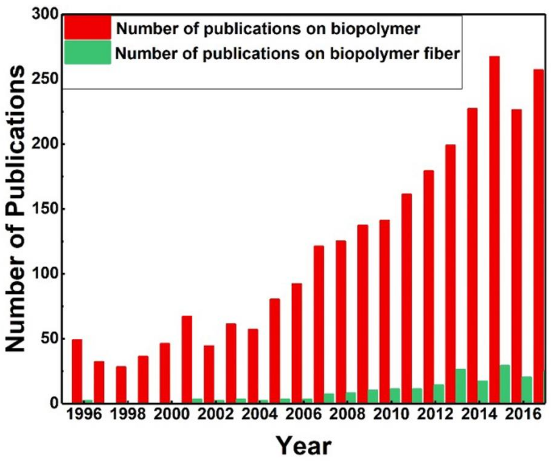
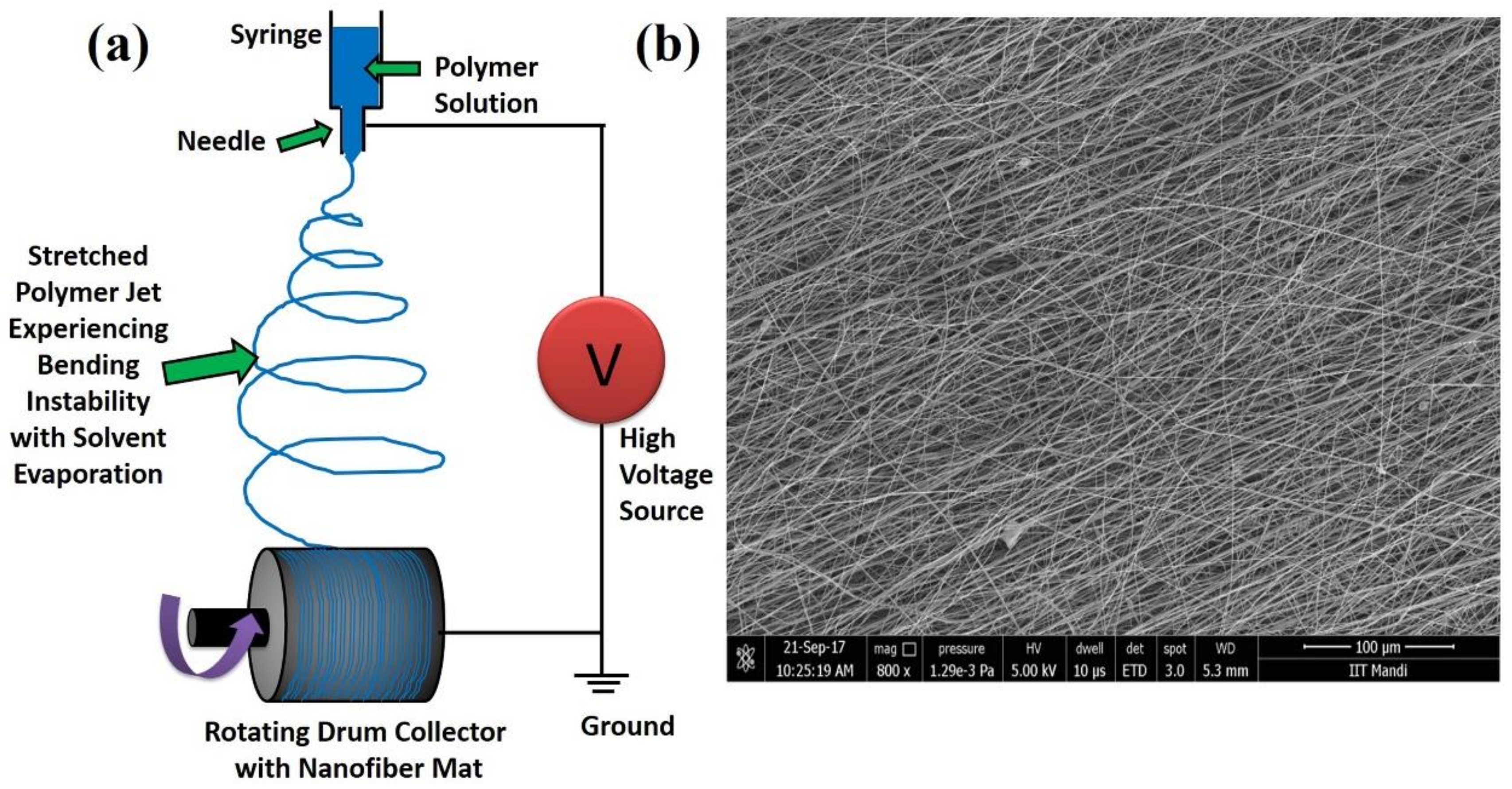
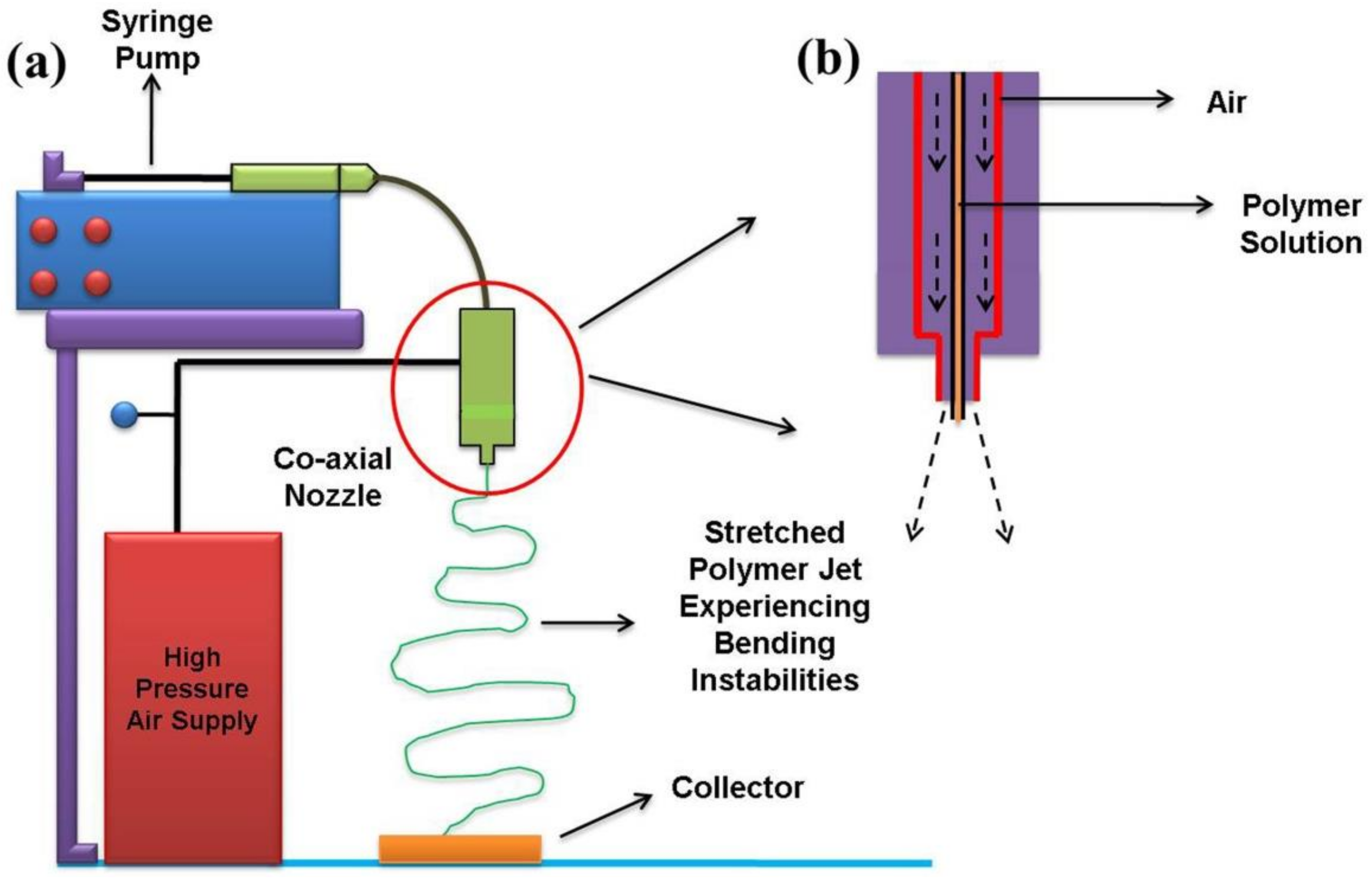
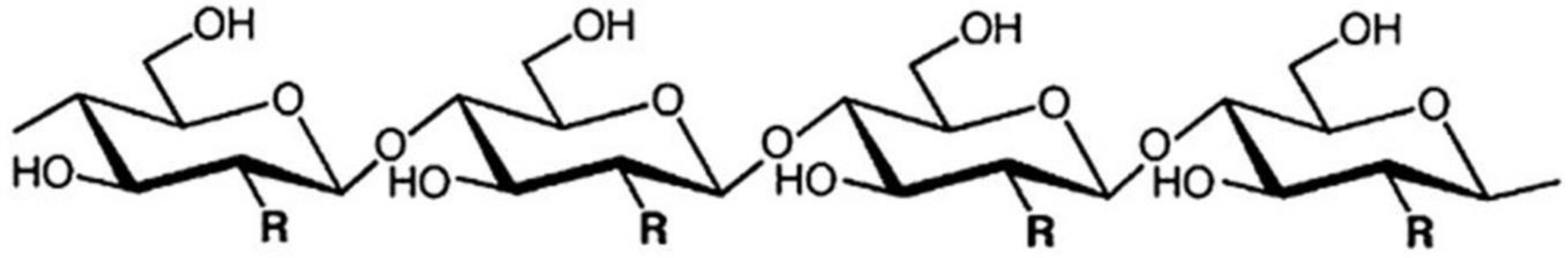
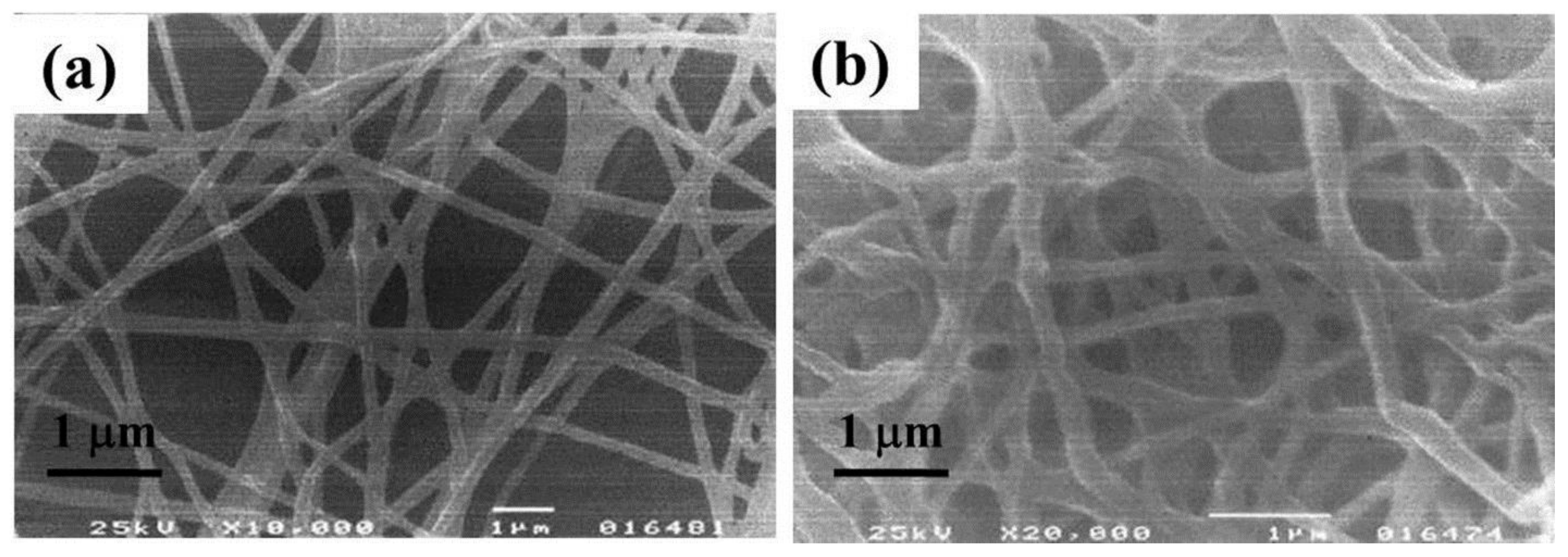
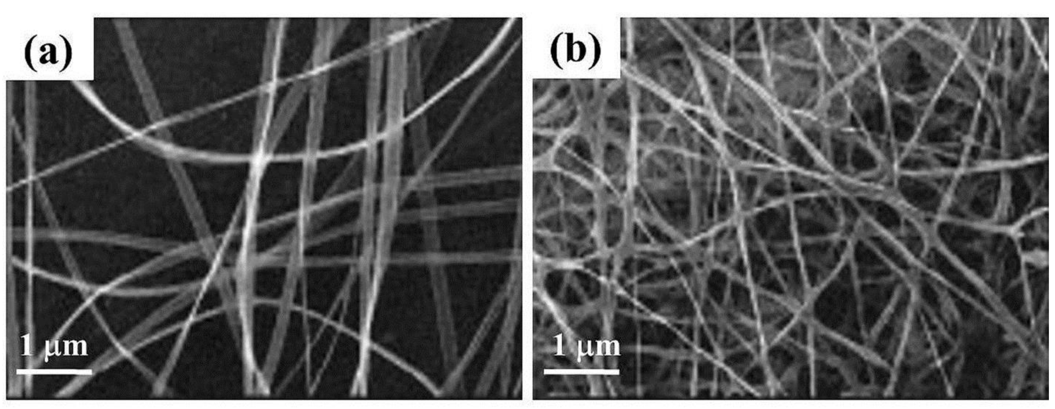
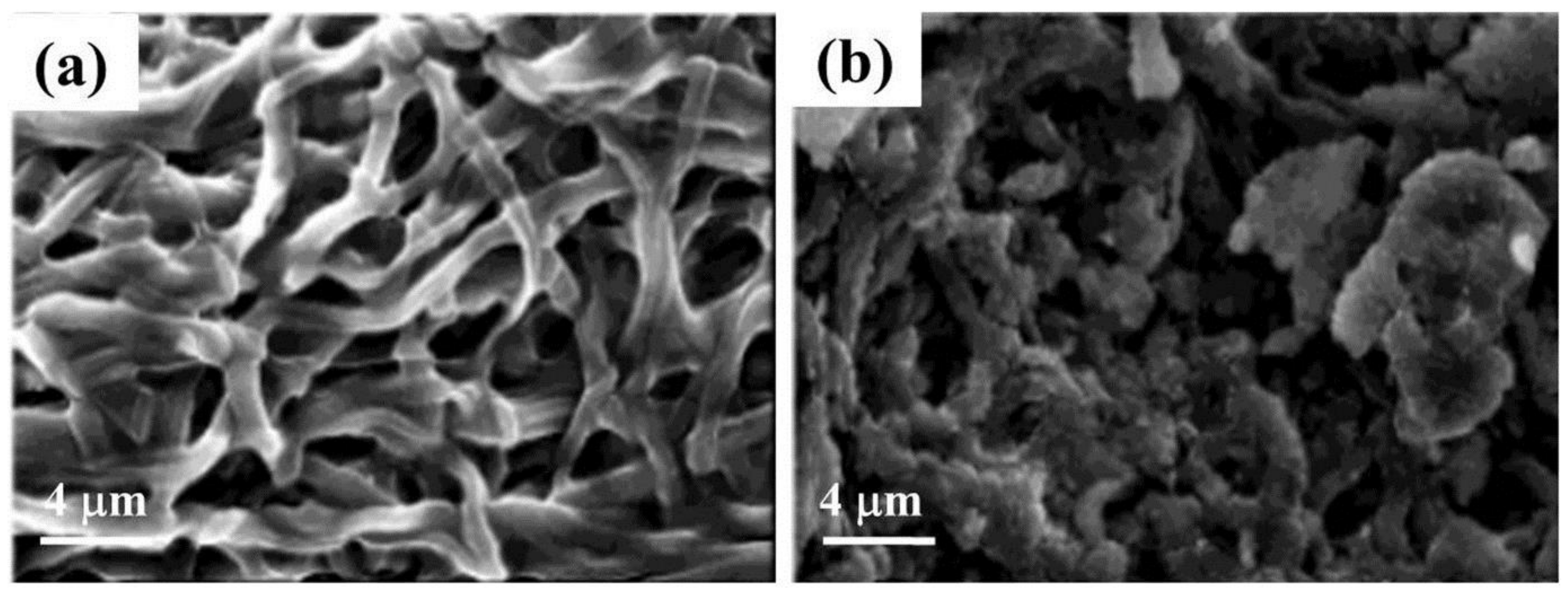
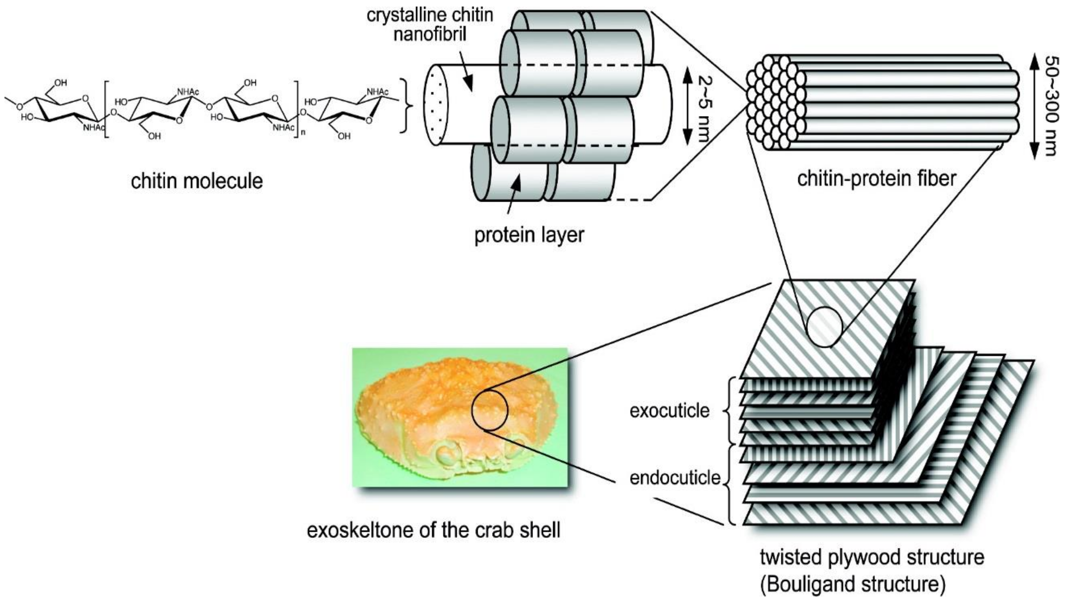
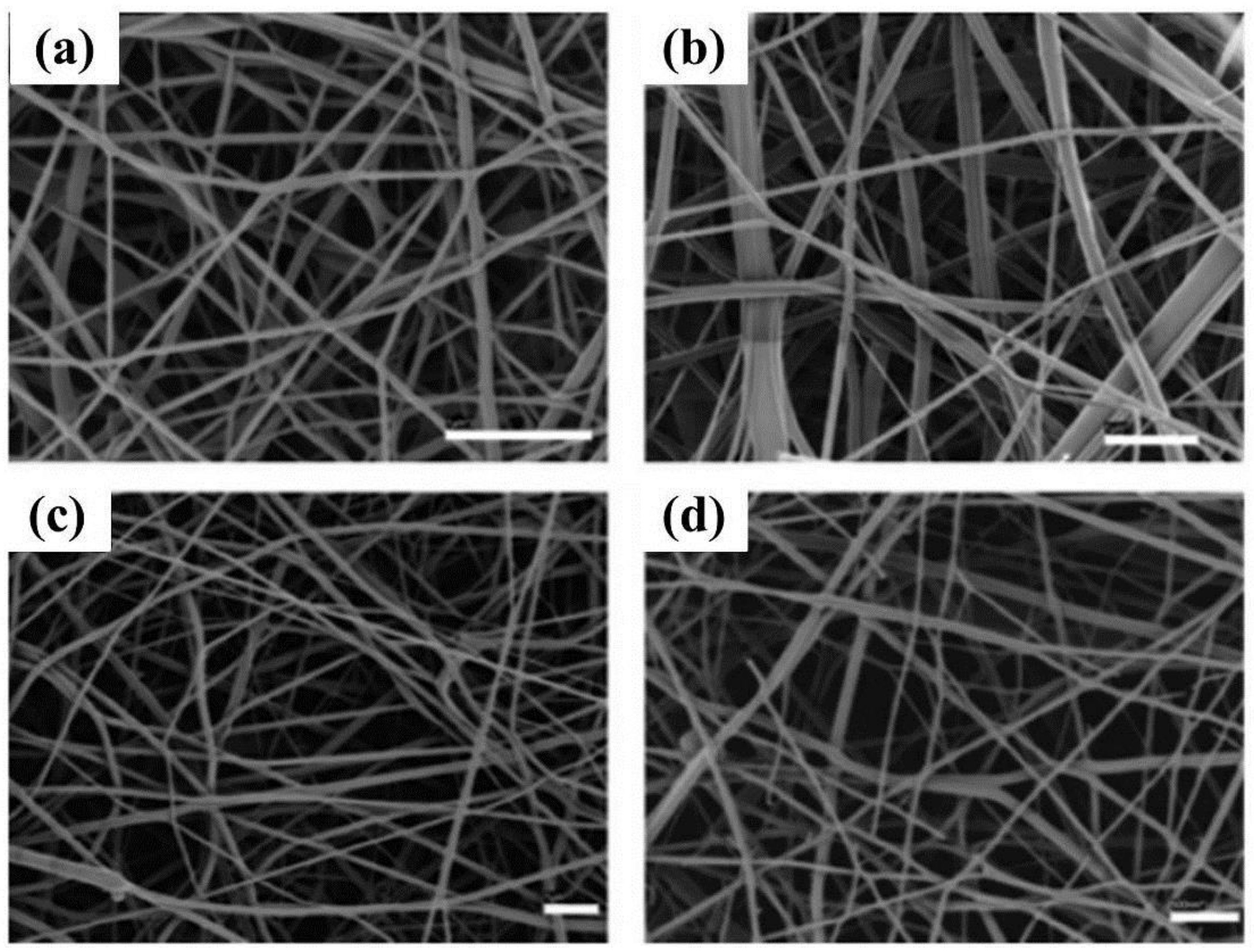
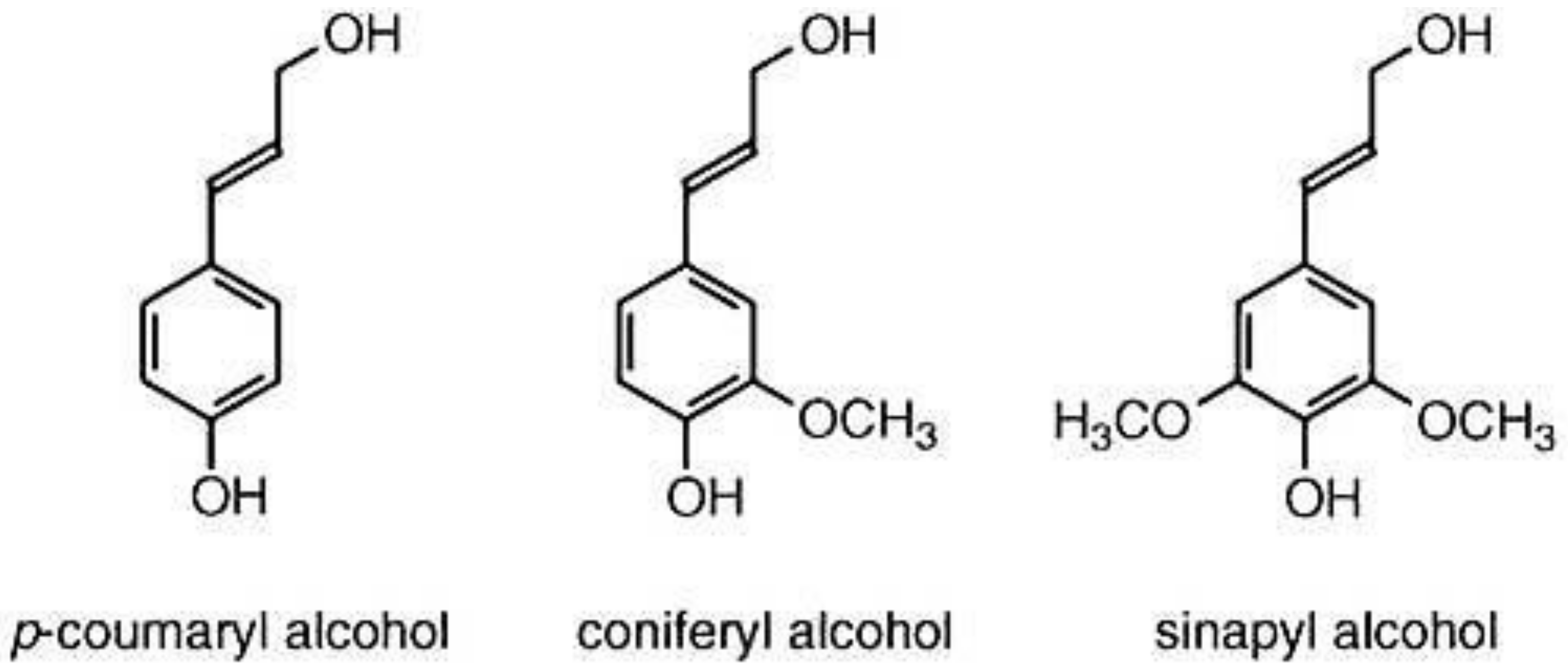
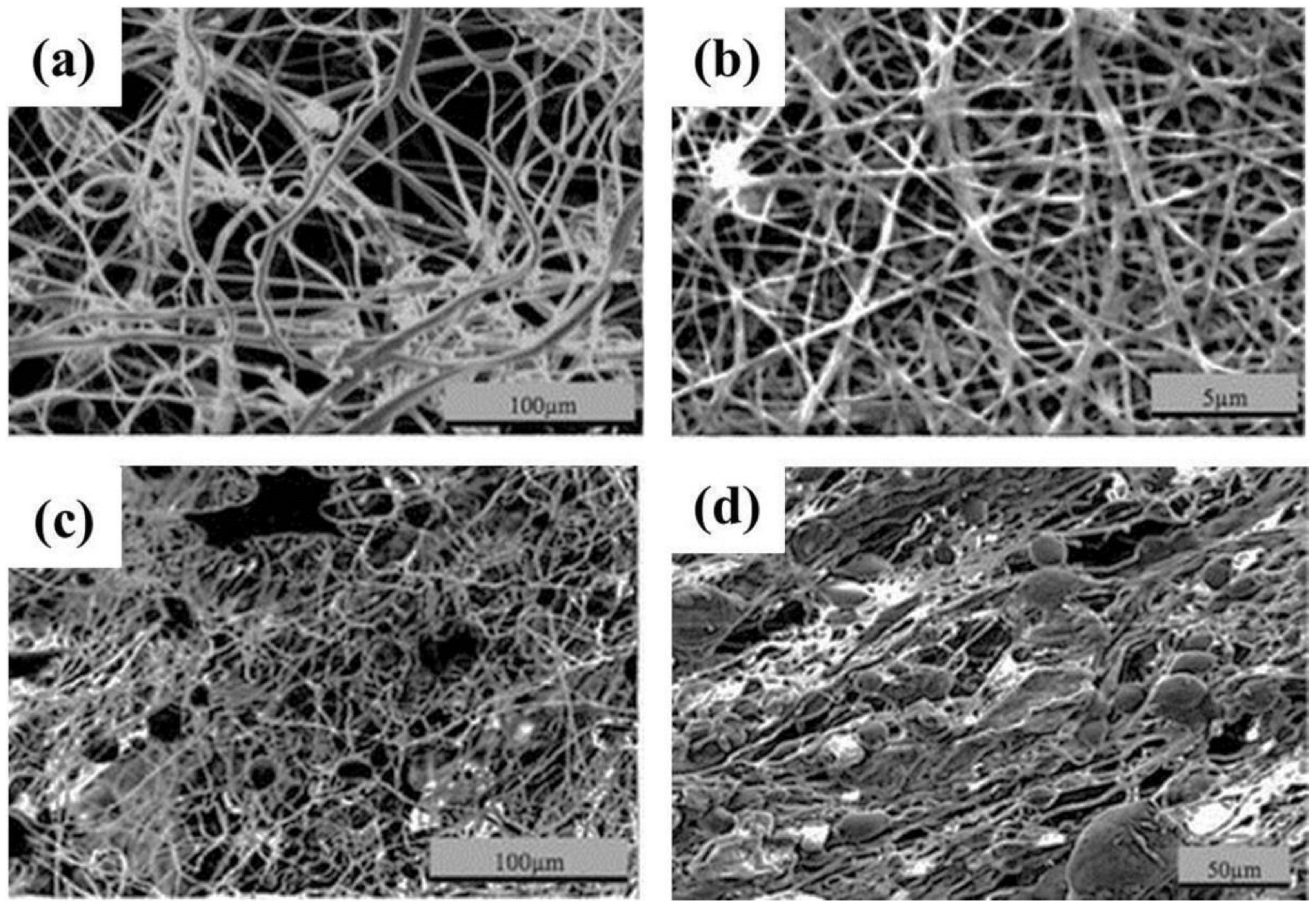
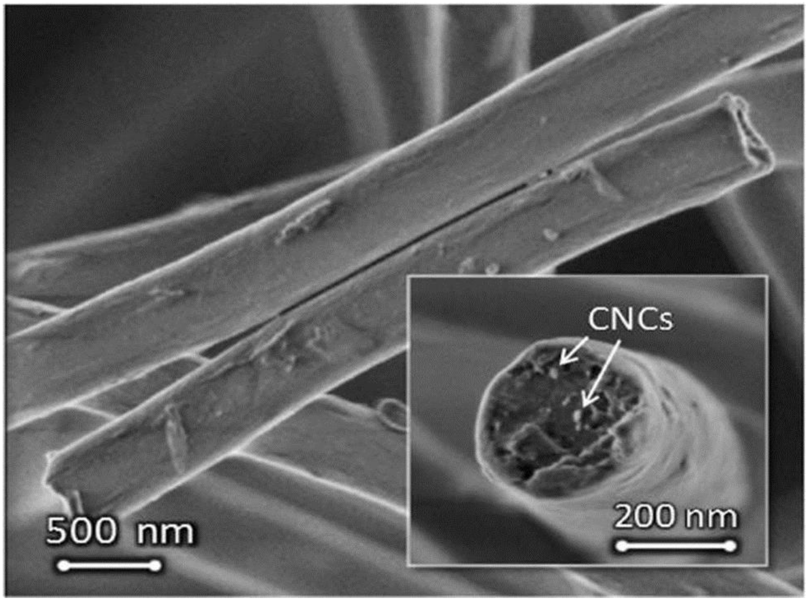
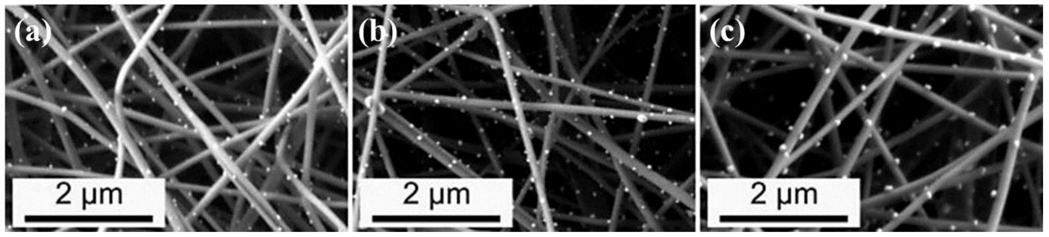
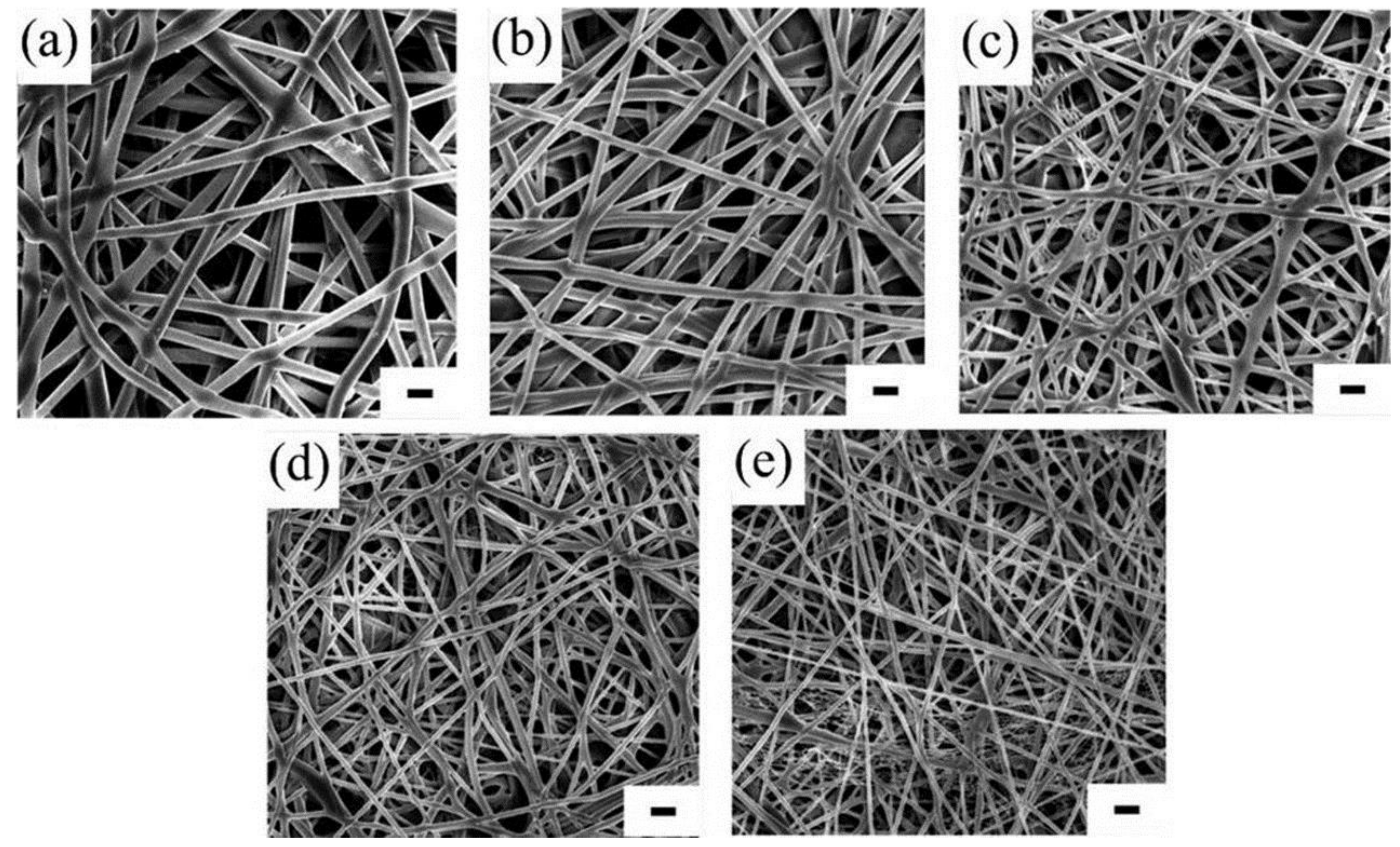
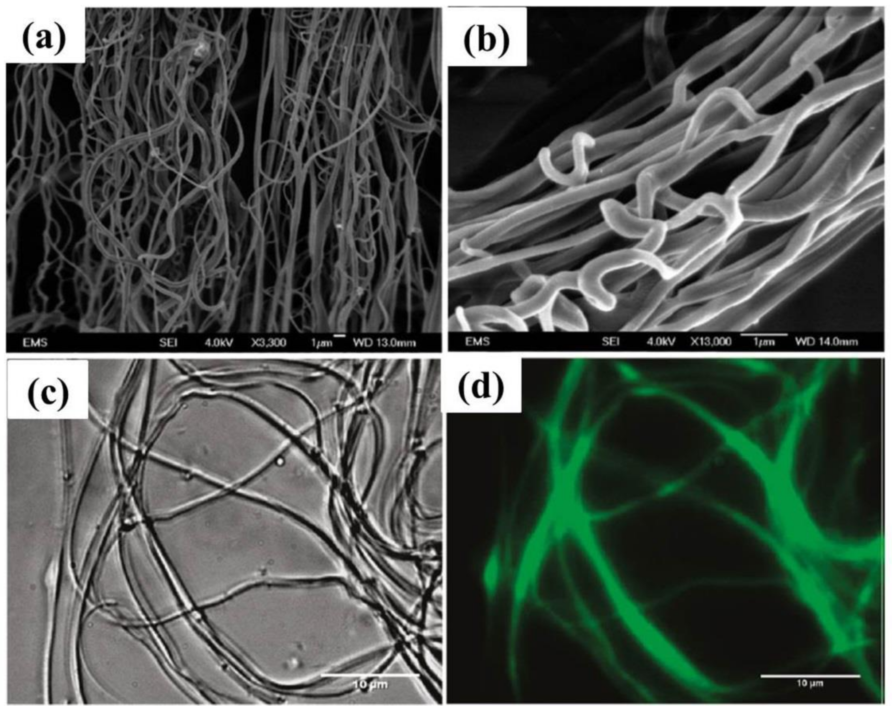
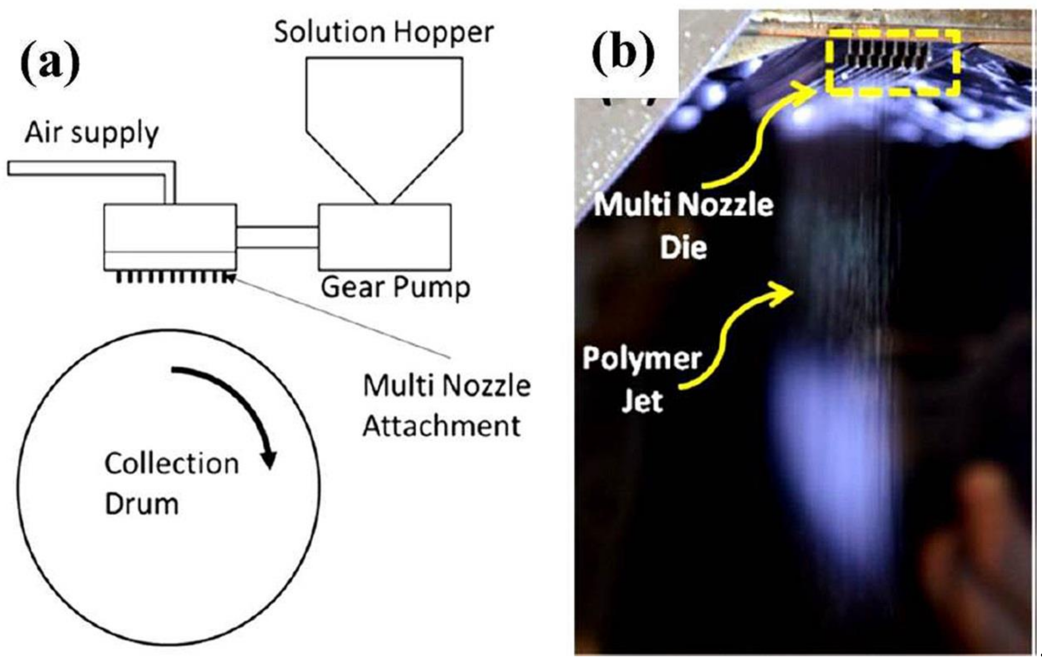
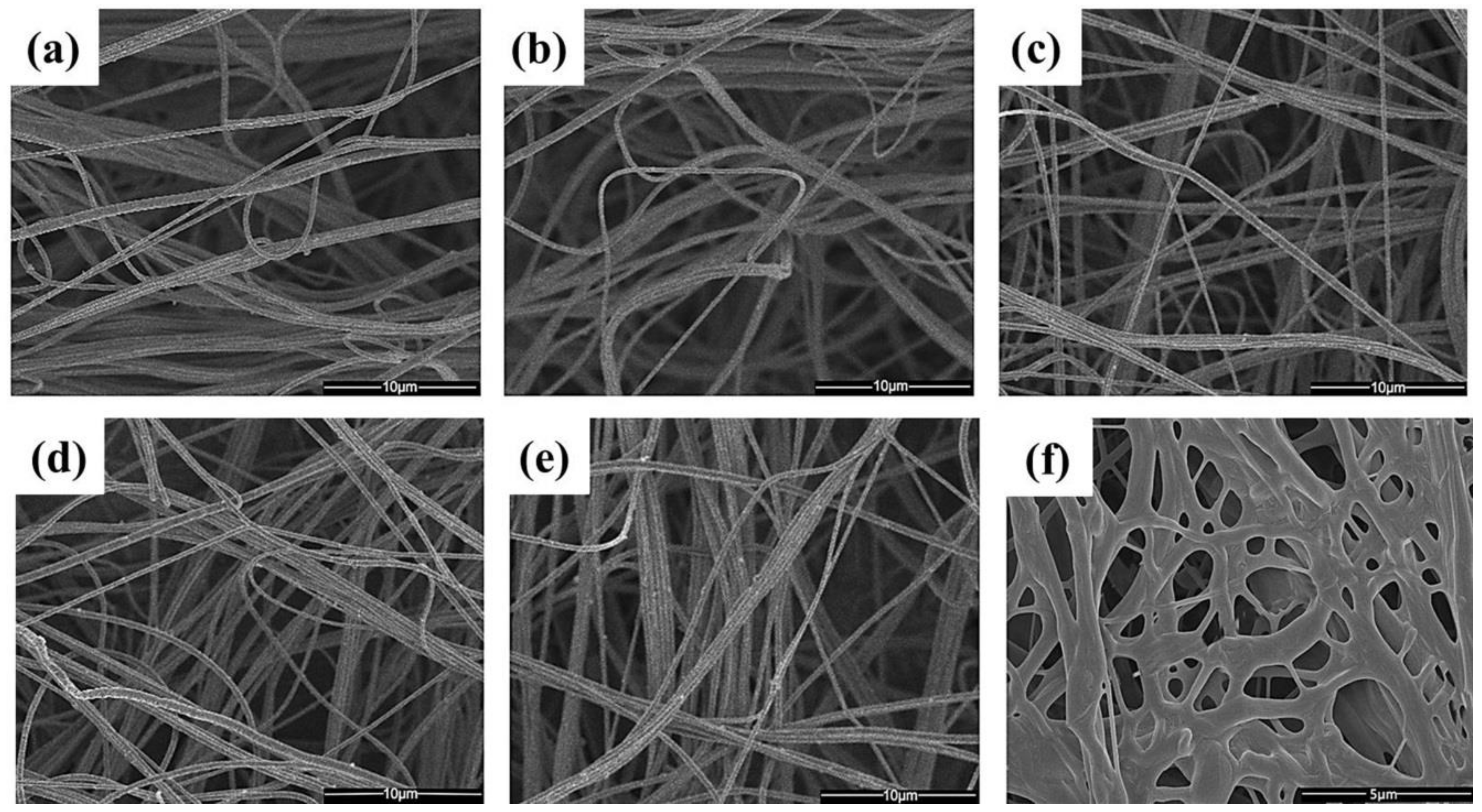
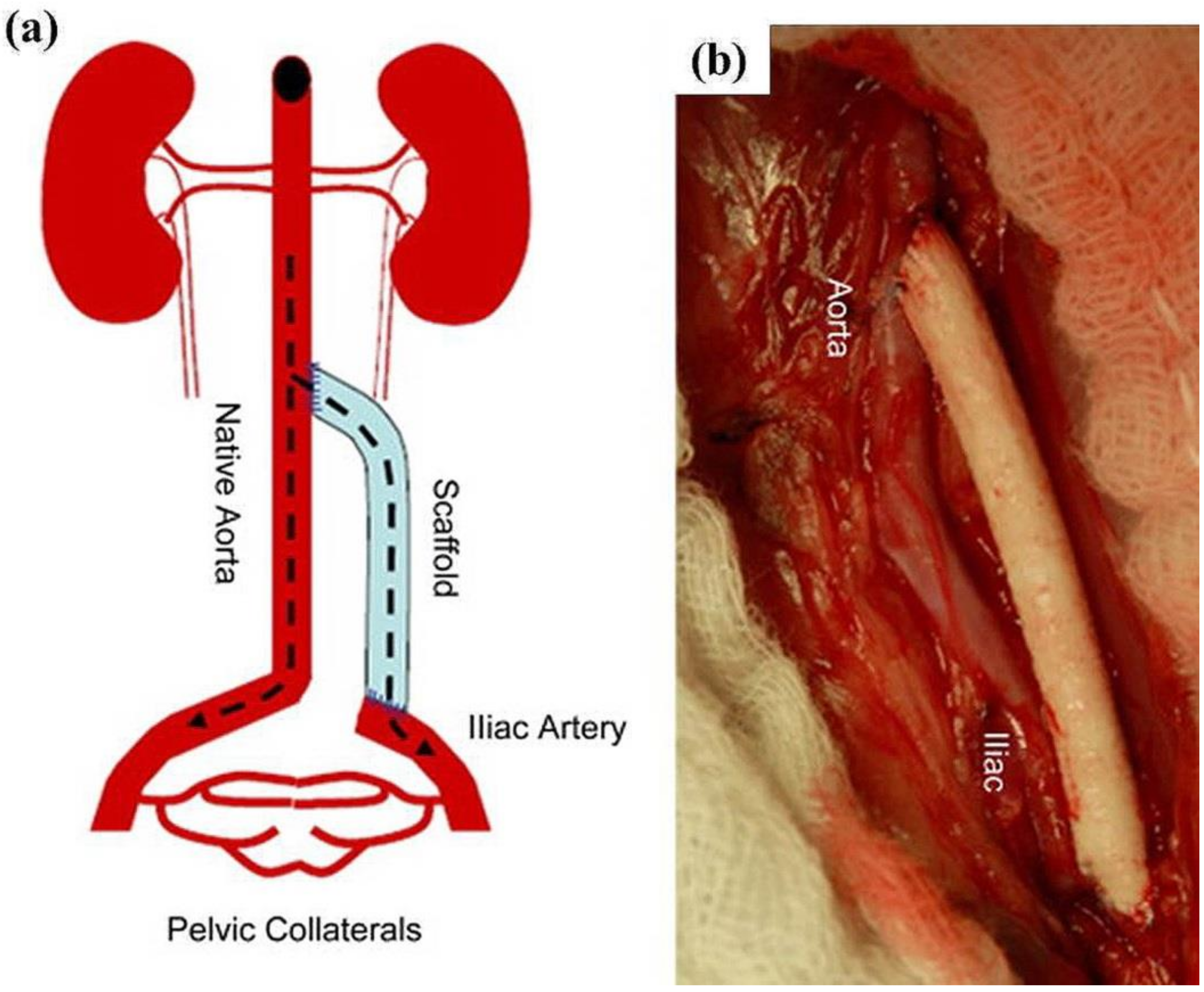
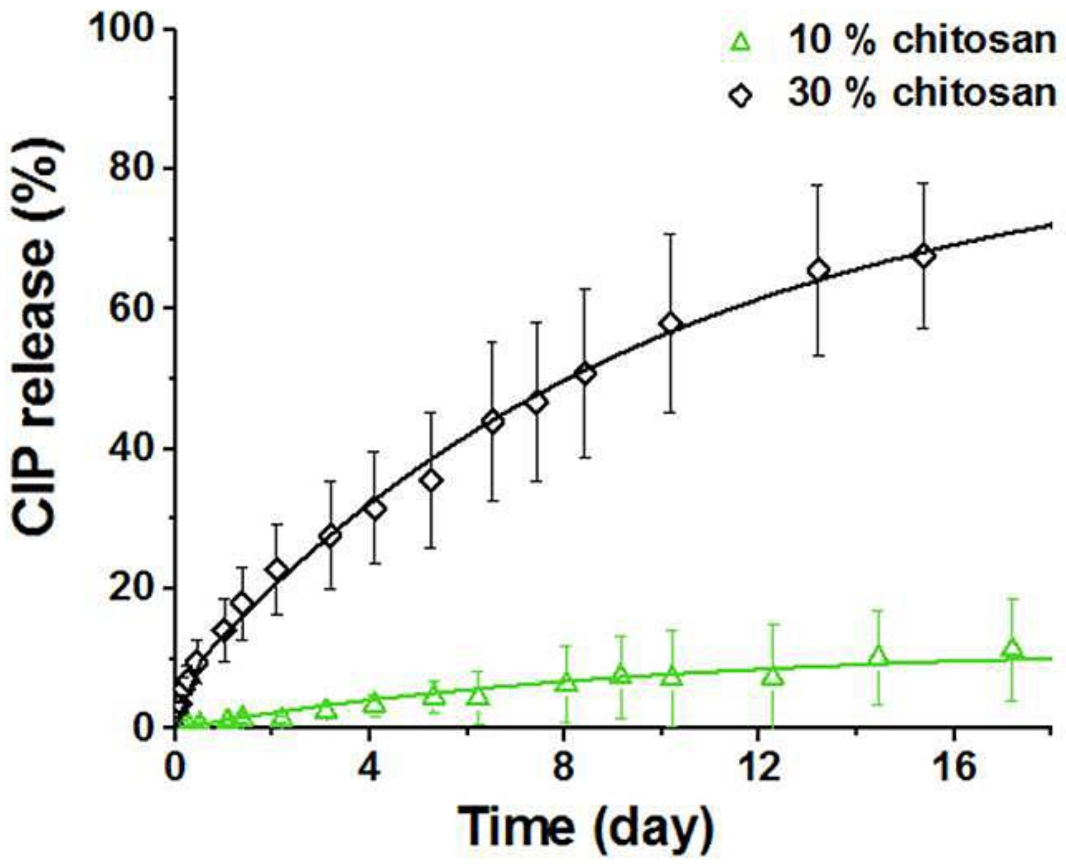
Table 1.
Governing electrospinning parameters of cellulose and its derivatives, and their blends and nanofiber dimensions.
Table 1.
Governing electrospinning parameters of cellulose and its derivatives, and their blends and nanofiber dimensions.
| Polymer | Solvent Used | Voltage (kV) | Collecting Distance (cm) | Flow-Rate (mL/h) | Diameter (nm) | References |
|---|---|---|---|---|---|---|
| Cellulose | NMMO/water | 9–10 | 10–15 | Not specified | 200–400 | [93] |
| HNO3/H3PO4 | 12 | 8 | 10 | 3940 | [96] | |
| Cellulose Acetate | H2O/Chloroform | 5 | 4 | Not specified | 16–2000 | [120] |
| Acetone/acetic acid/(DMAc) | 5–18 | 6–13 | Not specified | 100–1000 | [43] | |
| Acetone/water | 17 | 10 | 3 | 600–1910 | [112] | |
| Acetone/DMF/trifluoroethylene | 25 | 15 | 4 | 200–1000 | [121] | |
| Acetone/(DMAc) | 17 | 10 | 3 | 100–1000 | [119] | |
| Acetone/(DMAc) | 15 | 15 | 1 | 100–1000 | [122] | |
| Cellulose Acetate/PVP | Acetone/Acetic acid | 7–20 | 6 | 1.8–6.0 | 1000 | [97] |
| Cellulose/LiCl | LiCl/N,N-DMAc | 1–4 | 7–13 | 0.6 | 150–500 | [101] |
| LiCl/N,N- (DMAc)/N- (NMMO)/water | 1–4 | 10–20 | 3 | 270–750 | [107] | |
| Cellulose/PLA | Chloroform/acetone | 10 | 12 | 2.5 | 500–3000 | [123] |
| Ethyl Cellulose | THF and DMAc | 20 | 10 | Not specified | 100–2200 | [124] |
| Ethyl-Cyanoethyl Cellulose | (THF) | 20–50 | 5–20 | Not specified | 200 | [125] |
| Hydroxypropyl Cellulose | Anhydrous ethanol and 2-propanol | 10–30 | 10–15 | Not specified | <100 | [126] |
Table 2.
Summary of electrospinning parameters of lignin, lignin/carrier polymer, and their fiber dimensions.
Table 2.
Summary of electrospinning parameters of lignin, lignin/carrier polymer, and their fiber dimensions.
| Polymer | Solvent | Voltage Applied (kV) | Collecting Distance (cm) | Flowrate (mL/h) | Diameter (nm) | References |
|---|---|---|---|---|---|---|
| Lignin/PAN | N.N-DMF | 15 | 10 | 1.2 | 300 | [178] |
| DMF | 20 | 20 | 1 | 200–500 | [179] | |
| DMF | 26 | 25 | 1 | ~200 | [180] | |
| DMF | 16 | Not Specified | 1.6 | 400–100 | [181] | |
| Lignin/PEO | Ethanol/DMF/Water | 5.5–13.5 | 22.5 | 0.1 | ~400 | [182] |
| DMF | 6.5–7.0 | 10 | 1 | ~1000 | [183] | |
| (DMF)/methanol/methylene chloride | 5.5–13.5 | 22.5 | 0.1 | 85–875 | [169] | |
| DMF | 15 | 20 | Not Specified | 400–3261 | [184] | |
| Water | 20 | 22 | 0.2 | 300–12,000 | [185] | |
| DMF | 70 × 103 V/m | 0.2 m | 4.2 × 10⁻¹⁰ m3 · s−1 | 26–809 | [186] | |
| DMF | 20 | 10 | 0.5 | 300–1100 | [187] | |
| Ethanol | 9–14 | 14–20 | 1.8 | 234–1363 | [188] | |
| Lignin/PVA | Water | 26 | 25 | 1.2 | ~300 | [189] |
| 2-propanol | 26 | 25 | 1.2 | ~120 | [190] | |
| Water | 22 | 15 | 1 | 70–290 | [191] | |
| Lignin/Alumina | Ethanol | 14 | 15–20 | 0.5–4.0 | 500–4000 | [192] |
| Lignin/Cellulose | Water | 19 | 22 | 1.6 | 200–400 | [193] |
| Lignin/Cellulose CNCs | Water | 19 | 22 | 1.6 | 30,000–80,000 | [194] |
| Water | 19 | 22 | 1.6 | 4–200 | [195] | |
| Lignin/Cellulose/PET | TFA | 25 | 8 | 0.3 | 150–430 | [196] |
| Lignin/Chitosan/PVA | DMF | 14 | 22.5 | 0.1 | 77–1920 | [197] |
| Lignin/H3PO4 | Ethanol | 24 | Not Specified | 0.3 | >1000 | [174] |
| Lignin/Phosphorous/Platinum | Ethanol | 14 | 25 | 3 | 600–1000/600–3000 | [198] |
| Lignin/platinum-acetyl-acetonate | Ethanol | 12 | 20–25 | 0.06–0.8 | 400–1000 | [173] |
| Lignocellulosic | 1-ethyl-3methylimidazolium acetate | 35 | 15 | Not Specified | 100–1800 | [175] |
Table 3.
Electrospinning parameters of proteins and protein/carrier polymer and their nanofiber dimensions.
Table 3.
Electrospinning parameters of proteins and protein/carrier polymer and their nanofiber dimensions.
| Polymer | Solvent Used | Voltage Applied (kV) | Collecting Distance (cm) | Flow Rate (mL/h) | Diameter (nm) | References |
|---|---|---|---|---|---|---|
| Whey protein | Water | 0–30 | 7 | 10 | Not specified | [225] |
| Acetic acid/methanol | 60 | 18 | Not specified | 680–860 | [226] | |
| DI | 7.5–25 | 10 | 1–3 | 100–400 | [227] | |
| Soy-Protein | Acetic acid/DI | 28 | 15 | Not specified | 200–1200 | [221] |
| TFE/HFIP | 20–30 | 26 | 2.4 | 200–260 | [228] | |
| DMF | 20 | 13 | 2 | 100–205 | [212] | |
| Chloroform/DMF | 20–30 | 26 | 2.4 | 200–2000 | [229] | |
| HFIP | 25 | 25 | 90 | 200–300 | [230] | |
| Poly (DL-lactide)/BSA | THF | 20 | 15 | 1.6 | 47–634 | [231] |
| Poly (DL-lactide)/lysozyme | THF | Not specified | Not specified | Not specified | 110–620 | [206] |
| Poly (lactidecocaprolactone)/BSA | Chloroform | 15 | 15 | 1.0 | 20–910 | [208] |
| Dextran/PLGA/BSA | Chloroform/DMF/TFE | 13-15 | 15 | 0.6 | 214–548 | [232] |
| Globular proteins/Gelatin | Ethanol | 25 | 7.5–15 | 0.03–1.2 | 100–100,000 | [233] |
| Polycaprolactone/poly (ethylene-oxide)/lysozyme | Chloroform | 15 | 12 | 1.2 | 1000–1430 | [234] |
| Poly (lactic acid) | Dimethyl carbonate | Not specified | Not specified | Not specified | 220–970 | [235] |
© 2018 by the authors. Licensee MDPI, Basel, Switzerland. This article is an open access article distributed under the terms and conditions of the Creative Commons Attribution (CC BY) license (http://creativecommons.org/licenses/by/4.0/).
Share and Cite
MDPI and ACS Style
Kakoria, A.; Sinha-Ray, S. A Review on Biopolymer-Based Fibers via Electrospinning and Solution Blowing and Their Applications. Fibers 2018, 6, 45. https://doi.org/10.3390/fib6030045
AMA Style
Kakoria A, Sinha-Ray S. A Review on Biopolymer-Based Fibers via Electrospinning and Solution Blowing and Their Applications. Fibers. 2018; 6(3):45. https://doi.org/10.3390/fib6030045
Chicago/Turabian StyleKakoria, Ashish, and Sumit Sinha-Ray. 2018. "A Review on Biopolymer-Based Fibers via Electrospinning and Solution Blowing and Their Applications" Fibers 6, no. 3: 45. https://doi.org/10.3390/fib6030045
Note that from the first issue of 2016, this journal uses article numbers instead of page numbers. See further details here.