Article

Design and Performance Evaluation of Flame Retardant and Thermally Insulated Material-Integrated Multi-Functional Thermoplastic Corrugated Sandwich Panels

1
School of Materials Science and Engineering, Beihang University, Beijing 100191, China
2
Institute of Advanced Materials, Shandong Institutes of Industrial Technology, Jinan 250102, China
3
Huawei Device Co., Ltd. Device Reliability Laboratory, Shenzhen 518129, China
4
School of Materials Science and Engineering, University of Science and Technology Beijing, Beijing 100083, China
*
Author to whom correspondence should be addressed.
Coatings 2022, 12(11), 1719; https://doi.org/10.3390/coatings12111719
Submission received: 30 September 2022 / Revised: 4 November 2022 / Accepted: 7 November 2022 / Published: 10 November 2022
(This article belongs to the Special Issue Flame Retardant Coatings for Plastics and Textiles)

Abstract

:
Multifunctional composite panels for flame retardant and thermal insulation have not yet been studied. In the current study, we prepared sandwich sheets by using continuous glass fiber flame retardant polypropylene prepreg tape and compared the thermal insulation properties of different fillings. Corrugated sandwich panels, featuring a corrugated space filled with different materials, were prepared and their thermal and mechanical properties are tested and verified. Determining the two structural parameters that have the greatest influence on the heat transfer performance of corrugated sandwich panels has important guiding significance for the structural design of corrugated panels.

1. Introduction

Owing to its high strength, high specific stiffness, and energy absorption characteristics, sandwich structures play a key role in aerospace applications, automobiles and ships, transportation, and other fields. Further, the functionalization of sandwich structures can enable noise reduction and thermal insulation [1,2,3]. A sandwich structure consists of two thin panels at the top and bottom, and a core material with a certain thickness. The top and bottom panels are made of materials with a high strength and stiffness. When the sandwich structure is subjected to a lot of bending, the panels farther away from the neutral surface bear the tensile stress on the surface, while the core material divides and connects the top and bottom panels and disperses the shear stress. Typical panel materials include metal, plastic, wood, and fiber-reinforced composites. The commonly used core materials are of the corrugated, foam, dot matrix, honeycomb, and pillar types [4].
Corrugated sandwich structures are composed of a middle-corrugated core material and two panels. Owing to the presence of a corrugated core material, the corrugated sandwich structure exhibits significant anisotropy, its stiffness is perpendicular to the corrugated direction, and it is easier to bend parallel to the corrugated extension direction. The corrugated sandwich structure has the low weight and high strength of the sandwich structure, along with shear resistance and impact resistance. It also offers good ventilation performance. Further, the gap between the sandwich panels can be filled with various materials and components to achieve overall versatility. Thus, it is an interesting research direction to utilize this gap by filling it with thermally insulated materials.
Thermally insulated materials possess a low thermal conductivity (generally not more than 0.12 W m−1 K−1) and light and loose porous structures (such as foamed polymers or short-cut fiber felts); owing to the presence of pores, which are filled with gases of low thermal conductivity, they can also provide good thermal insulation. Thermally insulated materials are widely used in industrial production. For instance, insulation layers are wrapped around thermal pipes to reduce heat loss, and around refrigeration boxes to reduce the energy consumption. Traditional thermally insulated materials include glass fiber (GF), asbestos, rockwool, and silicate. New thermally insulated materials such as aerogel felt and vacuum plates are also receiving increasing attention. Based on their primary insulation mechanism, insulation materials can be categorized into porous/fiber materials, vacuum insulation materials, and retro-generation/radiation insulation coatings. Among these materials, GF-reinforced polypropylene composite materials have abundant raw material resources, are inexpensive and recyclable, and exhibit excellent mechanical properties.
An integrated thermal protection system (ITPS) refers to a sandwich thermal protection structure with both load-bearing and thermal insulation functions [5,6,7,8]. Its honeycomb or corrugated core can effectively reduce the weight of the system, and the filled thermally insulated material plays a key role in preventing the failure of the internal system. The ITPS has been widely studied in the field of hypersonic flight. A corrugated sandwich thermal protection system was first proposed by Bapanapalli et al. [9]. The corrugated sandwich structure, is a system which has a high cross-sectional moment of inertia whilst reducing weight, filling the void with efficient thermal insulation material, taking the mass per unit area as the target function, by establishing the response surface proximity to represent the constraint to solve the optimization problem, transient heat transfer analysis and buckling analysis by finite element. Materials Research and Design has designed a variety of thermal protection systems for hypersonic cruise and re-entry vehicles, covering C/C, C/SiC, SiC/C, SiC/SiC, etc., and conducted detailed structural analysis, taking acoustic and gravitational loads, buckling, air pressure, and surface friction conditions. Wei et al. [10] prepared a ZrO2 ceramic corrugated core sandwich insulation panel using gel casting technology and pressureless sintering technology. The panel exhibited a nominal density of only 2.4 g/cm3, three-point flexural strength of 298.4 MPa, and compressive strength of 20.2 MPa. They simulated the compression test using the finite element method. Xie et al. [11] established an optimization program for the design of a least weight integrated thermal protection system, which is the geometry of a corrugated core ITPS; the constraint is that the internal temperature and local stress must be lower than a certain value, the parametric design language code and the global convergence method of moving asymptote (GCMMA) for heat transfer analysis and thermodynamic analysis, saving 37% of the weight compared to the original design.
Existing thermal protection corrugated structures mostly use C/SiC/ZrO2 and other high-temperature-resistant materials as raw material systems [12,13,14,15,16]. These are applied in an extremely high-temperature environment with transient insulation and upper temperature as the design goal, while the corrugated thermal insulation structure with continuous fiber-reinforced thermoplastic matrix as the material system and its weight reduction and energy saving application in normal temperature steady-state heat conduction. Hence, the use of vacuum in corrugated sandwich structures still has certain research limitations.
The aim of the design and preparation of a thermoplastic composite corrugated sandwich pane is to achieve structural and functional integration for the flame retardant, thermal insulation and bearing properties with low thermal conductivity and excellent mechanical properties.
This study proposes that the use of continuous GF-reinforced flame-retardant polypropylene as a raw material to prepare multi-functional corrugated sandwich panels, in order to fully utilize the lightweight and high-strength characteristics of fiber-reinforced resin matrix composites.
The thermal and mechanical properties of the unidirectional fiber-reinforced resin matrix composites selected for the panels: corrugated core materials and glass wool filled with corrugated voids, nano-silica aerogels, foamed polyurethane, rock wool, aluminum silicate fibers, and other thermally insulated materials, are evaluated. Corrugated sandwich panels featuring a corrugated space filled with different materials were prepared, and their thermal and mechanical properties are tested and verified.
The novelty of our work is determining the two structural parameters that have the greatest influence on the heat transfer performance of corrugated sandwich panels by comparing a series of comparative tests on the performance of corrugated plates of different filler materials. By comparing the thermal and mechanical properties of corrugated sandwich panels made of different filling materials, this study provides a reference for the design and optimization of corrugated insulation sandwich panels. The flame retardant and thermally insulated material-integrated multi-functional thermoplastic corrugated sandwich panels will have broad application prospects in the field of civil composite materials because of the characteristics of functional structure integration. It can be used in refrigerators, containers, cold storage, refrigerated vehicles, caravans, building insulation, and other applications to reduce the heat leakage rate, improve protection and support, save costs, and reduce the energy consumption.

2. Materials and Methods

2.1. Raw Materials and Test Device

The raw materials, equipment manufacturers, and grades required for the experiments are listed in Table 1 and Table 2.

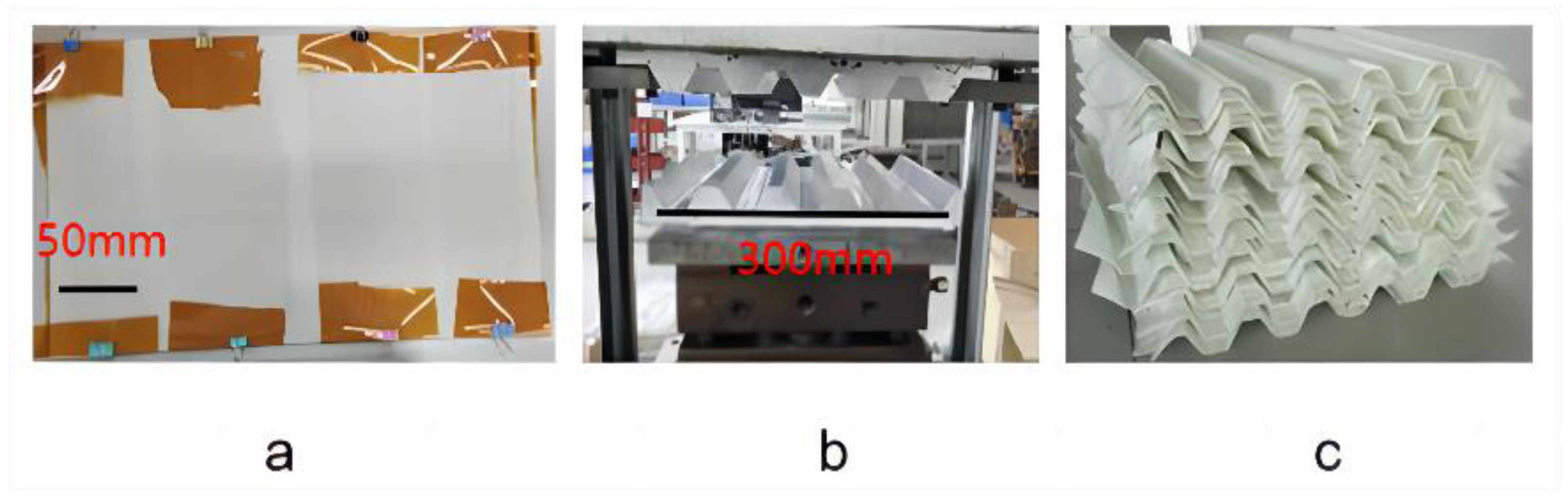
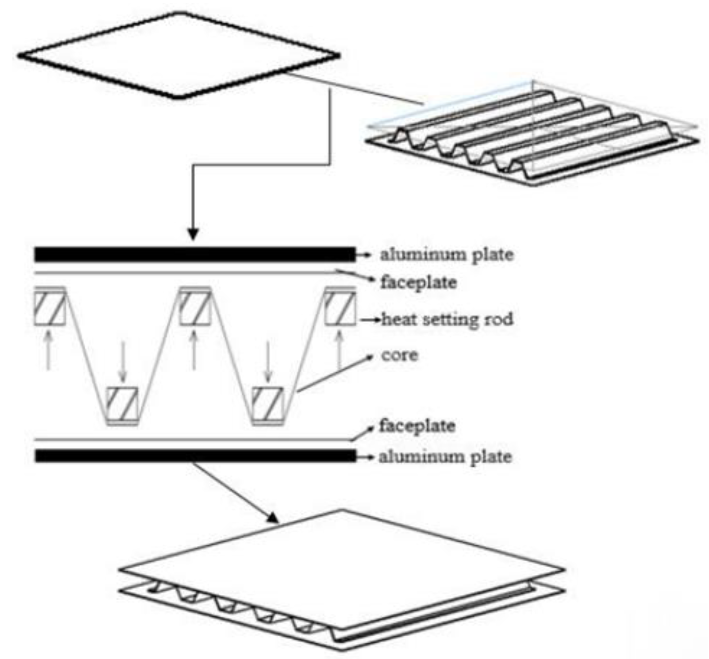
2.2. Preparation of Thermoplastic Corrugated Sandwich Panels

The top and bottom panels and corrugated cores were prepared by molding, and prepregs cut in advance were laid out sequentially and placed on a heating block to heat and melt. The prepregs were laid with a polyimide film, which facilitated the stripping and transfer of the prepreg after hot melting. It was also conducive for demolding of the final molded corrugated plate and for obtaining a smooth surface. The temperature of the heating block was set to 240 °C. Heating was performed for approximately 5 min, followed by melting and quickly transferring the melt to a molding press. The molding press parameters were a pressure of 15T and slow drop of 1.0 mm/s. After being maintained for 300 s at the corresponding temperature and pressure, the composite material was cooled and set, and the mold was carefully removed.
After their preparation, the corrugated core plate and top and bottom panels were arranged, and the heating rod was positioned at the crests and troughs. A temperature of 220 °C and pressure of 0.1 MPa were applied to connect the corrugated plates with the top and bottom panels. Subsequently, the heating device was turned off, and after approximately 5 min, the prototype was cooled, the top and bottom panels were carefully removed, and the corrugated surfaces were bonded together.
The insulating core materials of the thermoplastic corrugated sandwich panel were cut and polished to the appropriate size and filled into the corrugated plate interval. The distribution of the soft-core material in the corrugated panel was strictly controlled to be uniform. The polyurethane foam filling was poured into the corrugated panel by mixing and stirring the two components. The foam filled the voids of the corrugated core after foaming.
For the thermal radiation of the corrugated sandwich panel without the insulation material, the part that did not require hot-melt welding was marked on the top and bottom panels, aluminum foil tape was pasted in between, and the corresponding positions on the corrugated wall of the core material were also covered with aluminum foil tape. Subsequently, the upper and lower panels were welded together by heating and application of pressure. For thermal convection, the entire corner of the corrugated core structure was treated and sealed by vacuum bag extraction. Further, when measuring the thermal conductivity, a small-caliber suction pipe was extended through the side of the corrugated core. Simultaneously, an external digital vacuum gauge was used to monitor the internal air pressure. The preparation of thermoplastic corrugated sandwich panels can be seen in Figure 1 and Figure 2.

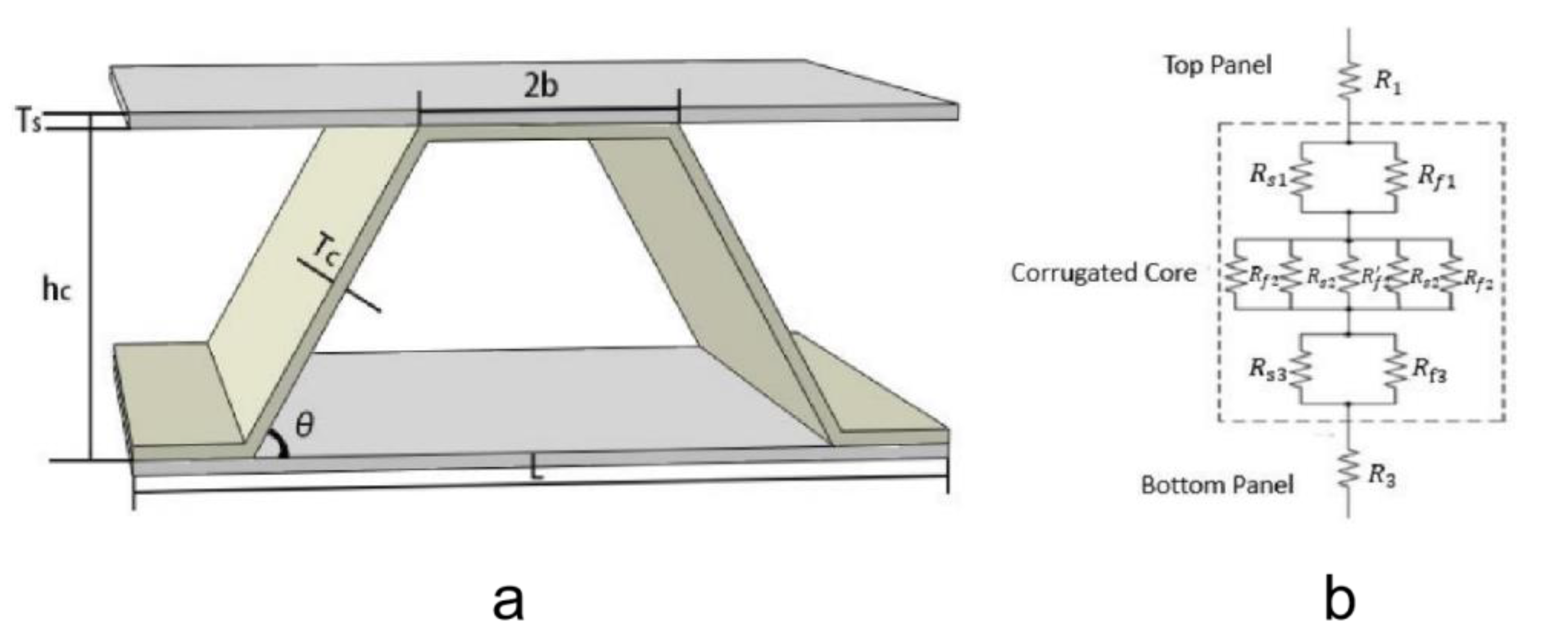
2.3. Heat Transfer Theory and Related Calculation Formulas

In steady-state heat transfer, the heat flow was compared to the current; the temperature difference between the two sides of the thermally insulated structure was similar to the voltage difference; and the ratio of the temperature difference to the heat flow was defined as the thermal resistance. The Fourier heat transfer formula is as follows:
Q = λ × A × Δ T Δ x
where Q is the heat flow (J/s), and λ is the thermal conductivity, and the measure unit is W m−1 K−1. ‘A’ is the area perpendicular to the direction of the heat flow, ΔT is the temperature difference between the cold and hot ends, and Δx is the distance between the cold junction and hot end.
For homogeneous regular structures, the thermal resistance is calculated as follows:
R = Δ T Q = Δ x λ × A
Dimensional numbering and simplified calculation of corrugated plate elements can be seen in Figure 3. Based on theoretical calculations, it can be concluded that the calculation method for the overall effective thermal resistance in the complex heat transfer structure is equivalent to that for the resistance. The effective thermal resistance can be calculated using the following formulas for series and parallel resistances:
R e f f = R 1 + R 2 + R 3
(series thermal resistance)
R e f f = [ 1 R 1 + 1 R 2 + 1 R 3 ] 1
(parallel thermal resistance)
Figure 3. (a) Schematic diagram of corrugated plate structural elements. (b) Schematic diagram of the thermal resistance series parallel connection relationship of each part of the corrugated sandwich panel.
Coatings 12 01719 g003
The thermal conduction of the corrugated sandwich panel from the top panel to the bottom panel was divided into five parts, and the thermal resistance of each part was combined based on the thermal resistance string parallel model to obtain the overall thermal resistance. This can be converted into a Fourier formula to calculate the effective thermal conductivity of the structure, λeff. During the calculation, it is also necessary to consider the anisotropic conductivity of a unidirectional GF-reinforced polypropylene composite plate. To simplify the calculations, a ripple structure with a width of 1 is used.
R 1 = R 3 = T s λ s 22 × L
where R1 and R3 are the thermal resistances of the top and bottom panels, respectively, T s is the thickness of the top and bottom panels, λ s 22 is the unidirectional composite plate axis guide thermal coefficient, and L is the characteristic size of the ripple period.
The Rs1 (Rs3) and Rf1 (Rf3) values of the core material represent the equivalent thermal resistances of the two parts of the corrugated core material. Owing to the periodicity of the corrugated structure, it was equivalent.
R s 1 / / R f 1 = R s 3 / / R f 3 = T c λ c ( 2 b + 2 h c 3 T c t a n θ ) + λ s 22 ( 2 b + 2 T c s i n θ T c t a n θ )
where Tc is the thickness of the ripple; λc is the thermal conductivity of the filling material; and b, hc, and θ are the characteristic size parameters of the corrugated core. λs22 is the guiding thermal coefficient of the unidirectional composite plate shaft.
The middle of the core material is parallel to the thermal resistance of the filler material/corrugated plate/filler material/corrugated material/filler material.
R f 2 / / R s 2 / / R f 2 / / R s 2 / / R f 2 = h c 2 T c λ c ( 4 b + 2 h c 4 T c t a n θ ) + λ s ( 2 T c s i n θ )  
where λs′ is the effective thermal conductivity of the core along the orientation of the unidirectional composite plate and perpendicular to the ripple thickness.
Let the direction cosine between the coordinate axes in the two coordinate systems of Zo-Yo-Xo and Z′-Y′-X′ be:
Z′-Y′-X′ is the coordinate system of the three main directions of the unidirectional composite plate. According to the Fourier heat transfer formula, the relationship between the heat flow in the three directions and thermal conductivity and temperature gradient is:
[ q X q Y q Z ] = [ λ 11 0 0 0 λ 22 0 0 0 λ 33 ] [ T X T Y T Z ]
Among them, the equal is the heat flow per unit area in the three main directions, and the other is the thermal conductivity in each main direction of the material.
The Zo-Yo-Xo coordinate system is a redefined coordinate system along the direction of the ripple thickness.
[ q X o q Y o q Z o ] = [ λ 11 λ 12 λ 13 λ 21 λ 22 λ 23 λ 31 λ 32 λ 33 ] [ T X o T Y o T Z o ]
After the compound function is derived and the matrix is transformed, we obtain the following matrix:
[ λ 11 λ 22 λ 33 λ 12 λ 13 λ 23 ] = [ l 1 2 m 1 2 n 1 2 l 2 2 m 2 2 n 2 2 l 3 2 m 3 2 n 3 2 l 1 l 2 m 1 m 2 n 1 n 2 l 1 l 3 m 1 m 3 n 1 n 3 l 2 l 3 m 2 m 3 n 2 n 3 ] [ λ 11 λ 22 λ 33 ]
When the ripple inclination is, the directional cosine between the two coordinate systems is:
λ 22 = l 2 2 λ 11 + m 2 2 λ 22 + n 2 2 λ 33 = s i n 2 θ λ 11 + c o s 2 θ λ 22
The total thermal resistance of the corrugated sandwich panel is:
R t o l = R 1 + R s 1 / / R f 1 + R f 2 / / R s 2 / / R f 2 / / R s 2 / / R f 2 + R s 3 / / R f 3 + R 3
λ e f f = ( h c + 2 T s ) λ s 22 2 T c + L ( 2 T s ( 2 b + 2 T c s i n θ T c t a n θ ) + λ c λ s 22 ( 2 b + 2 h c 3 T c t a n θ ) + h c 2 T s λ s λ s 22 2 T c s i n θ + λ c λ s 22 ( 4 b + 2 h c 4 T c t a n θ ) )
Based on the above formulas, the effective thermal conductivities of corrugated plates with sandwich structures of different materials can be calculated.

2.4. Performance Characterization

2.4.1. Thermal Conductivity

The thermal conductivity of the filled material was tested using the steady-state plate method with a DZDR-PL low-temperature plate thermal conductivity system.
Regular hexagonal samples of a certain thickness were placed between the two plates, which were hot and cold. This formed a certain temperature gradient above and below the sample. The heat flow through the sample was measured using a corrected heat flow sensor. The thermal conductivity could be calculated by considering the sample thickness, temperature gradient, and heat flow through the sample.
The instrument coefficients were corrected with a standard board of thermal conductivity 0.024 W m−1 k−1 before testing. The sample size used for the test was 300 mm × 300 mm, and the thickness was between 15 and 30 mm. The temperatures of the cold plate and hot plate were 10 °C and 50 °C, respectively. The temperature field of the plate thermal conductive instrument was stable for approximately 1.5 h. The temperature change was recorded by bonding the thermocouple at the center of the top and bottom panels and at the center of the ripple in the thickness direction. The ambient temperature was maintained at 25 ± 3 °C, and the relative humidity was 40 ± 10% during the test.

2.4.2. Coefficient of Thermal Diffusion

When the sample size is small, the thermal conductivities of the material and the unidirectional composite laminates can be determined using the laser flash method. The laser irradiates high-intensity energy pulses on a small and thin specimen. The energy of the pulses is absorbed by the front surface of the sample, which increases the temperature of the back surface. The test instrument records the temperature of the surface after laser irradiation (temperature self-remembering curve) and calculates the thermal diffusion coefficient based on the thickness of the specimen and time required for the temperature of the posterior surface to rise to the maximum value in a certain ratio. Thermal conductivity measurements also require knowledge of the specific heat and density of the specimen.
  λ ( T ) = α ( T ) × C p ( T ) × ρ ( T )
The unidirectional GF-reinforced polypropylene prepreg (60% fiber content) was cut into rectangles and laid in 48 layers. After wiping the two aluminum plates with alcohol, the release agent was applied, the laid prepreg was placed between the two aluminum plates, and the plates were wrapped with high-temperature tape. The heating block temperature was set to 240 °C and the sample was placed after the temperature reached the set value. After 5 min, the sample softened and was quickly transferred to the press mold for heating and pressurization. The composite sheets were removed after cooling. Several thin strips were cut on the plate, along and perpendicular to the fiber direction; following which, squares measuring 6 mm × 6 mm × 1.5 mm were obtained by engraving, and then slightly sanded with sandpaper. We prepared at least three samples in each direction. The thermal diffusion coefficient of the sample was tested using a laser scintillator with a reference temperature of 25 °C, and with at least three valid data points in each direction.

2.4.3. Specific Heat Test

A low-temperature synchronous thermal analyzer was used for the specific heat test, with sapphire as the standard sample, a temperature range of −60 °C–70 °C, and a temperature rise rate of 10 K/min.

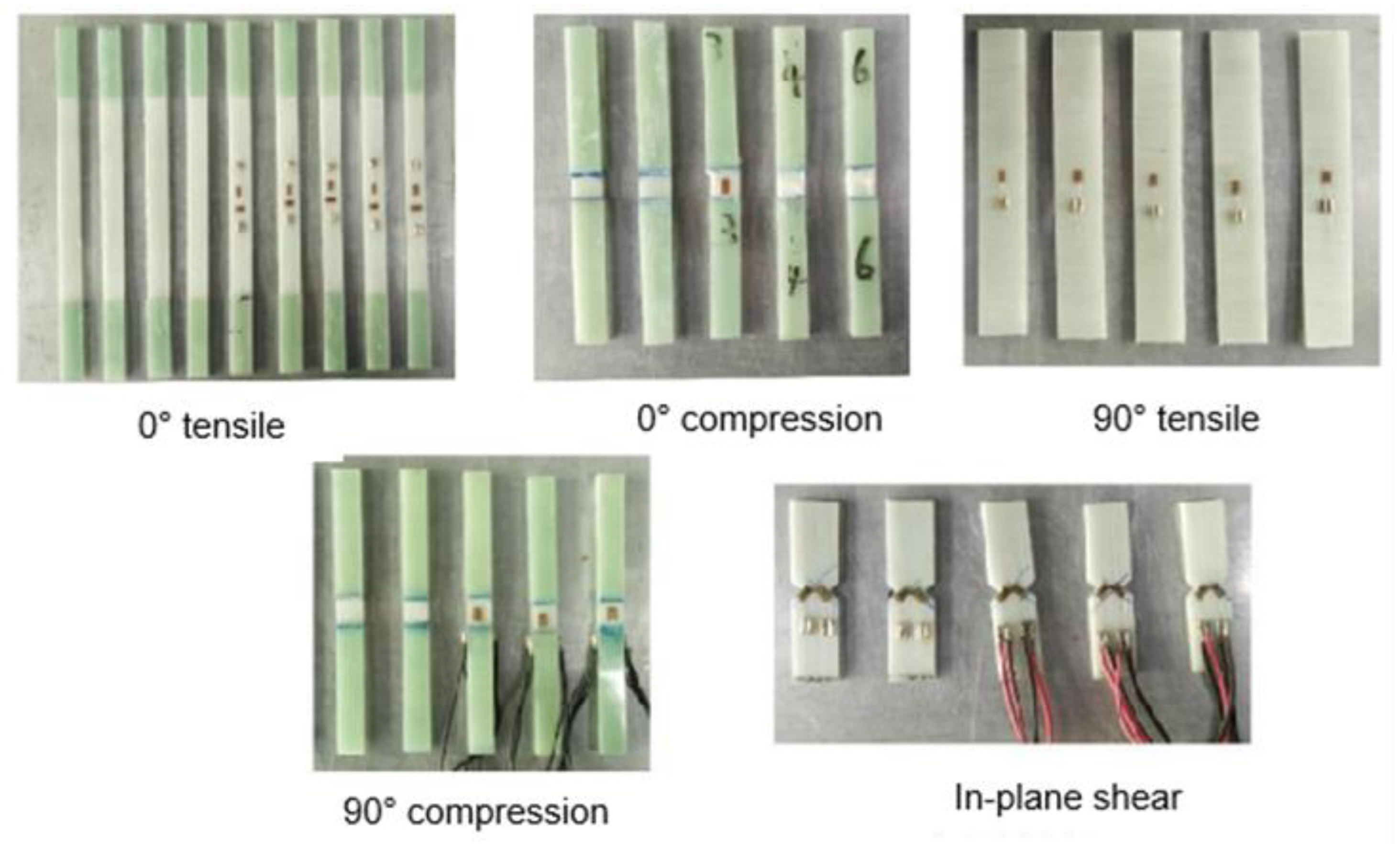
2.4.4. Mechanical Property Test

The sample for the mechanical property test was prepared using the hot-melt method to press the laminate to the required thickness.
Rectangular specimens and their V-notches in the in-plane shear performance test were obtained by sculpting. Adhesive strain gauges and terminal blocks at designated locations on the surface of the cut and polished specimens were welded to the wires.
The mechanical properties of the unidirectional composite laminate were tested using a WDW-100 electronic universal testing machine. The test results were the average of the results for five valid specimens.
The test sample to measure the compression performance of the filling material was a square specimen with a size of 100 mm × 100 mm or 200 mm × 200 mm and a thickness of 30–50 mm. During the test, two rigid, smooth parallel metal plates were placed above and below the specimen. The indenter of the mechanical tester applied a compressive load at a constant rate, perpendicular to the upper surface of the specimen, at a loading speed of 5 mm/min. Each sample provided at least three valid data points.
For loose materials such as aerogels, fiberglass felts, and rock wool, the sample was placed in a square mold similar to a compression chamber to limit its lateral deformation perpendicular to the loading direction. The loading speed was 10 mm/min, and the experiment was stopped when the test force increased sharply, or deformation occurred by up to 65%.
The mechanical properties of the corrugated sandwich panel were characterized by a flat pressure test, taking into consideration the corrugated cycle structure. The sample size was appropriately increased to 150 mm × 150 mm, including two repetition cycles of four corrugated units; the corrugated upper and lower panels were in contact with two rigid metal plates; the placement direction of the bellows was consistent during the test, the two crests were located on the upper side, the loading speed was 0.5 mm/min, and each set of samples provided at least five valid data points. Different kinds of mechanical test specimens can be seen in Figure 4.

3. Result and Discussion

3.1. Thermal Properties

At 25 °C, the thermal diffusion coefficient of the unidirectional GF-reinforced polypropylene composite sheet along the fiber axis was 0.257 (mm2/s), and that along the radial direction of the fiber was 0.462 (mm2/s); the specific heat of the sample was 1.037 J/(g·K), and the density of the composite plate was 1.627 g/cm3.
Comparison of thermal insulation properties of different materials can be seen in Table 3.

3.2. Comparison of Theoretical and Experimental Values of Effective Thermal Conductivity

It can be seen in Table 4, among the measured thermal conductivities of the several sets of different filling materials, the corrugated aerogel plate had the best thermal insulation effect (0.04 W m−1 K−1), whereas that of the aluminum-silicate-filled corrugated plate was the worst, at slightly lower than that of the untreated corrugated plate (0.142 W m−1 K−1). The thermal conductivities of the foam polyurethane and GF felt-filled corrugated boards also dropped to approximately 0.05 W m−1 K−1.
For each group, the predicted values were slightly higher than the experimental values. This is because, in the initial thermal conductivity test, the unidirectional composite laminate was tested using the laser flash method, while the filled material and corrugated sandwich panel were tested using the steady-state flat plate method. In the laser flash method, the front of the sample received the pulsed energy, along the thickness direction to the back. To minimize the heat transfer loss, a ceramic material with a low thermal conductivity was used as a support for the test equipment. When the thermal conductivity of the test sample itself was low (less than 0.1 W m−1 K−1), the test process was significantly affected by the heat transfer of the holder, resulting in a larger measured value than the actual value. Therefore, the thermal conductivity of the composite laminate was slightly higher than the actual value, and in the subsequent predictive analysis and simulation modeling, the thermal conductivity of the composite material used was high, resulting in the overall predicted value being slightly higher than the experimental value.
When no treatment was conducted on the corrugated sandwich panel and heat insulation was provided only by air (which has a low thermal conductivity), it was difficult to meet the thermal conductivity requirements of the insulation material due to thermal convection and thermal radiation.
Overall, the corrugated sandwich panel filled with thermally insulated material had a lower thermal conductivity than an air-corrugated sandwich board. The corrugated plate filled with the aerogel exhibited the best thermal insulation performance compared to the corrugated sandwich board at low pressure and low radiation dose. From the perspective of thermal insulation, the corrugated sandwich boards filled with the GF felt, aerogel, and polyurethane foam can meet application requirements.

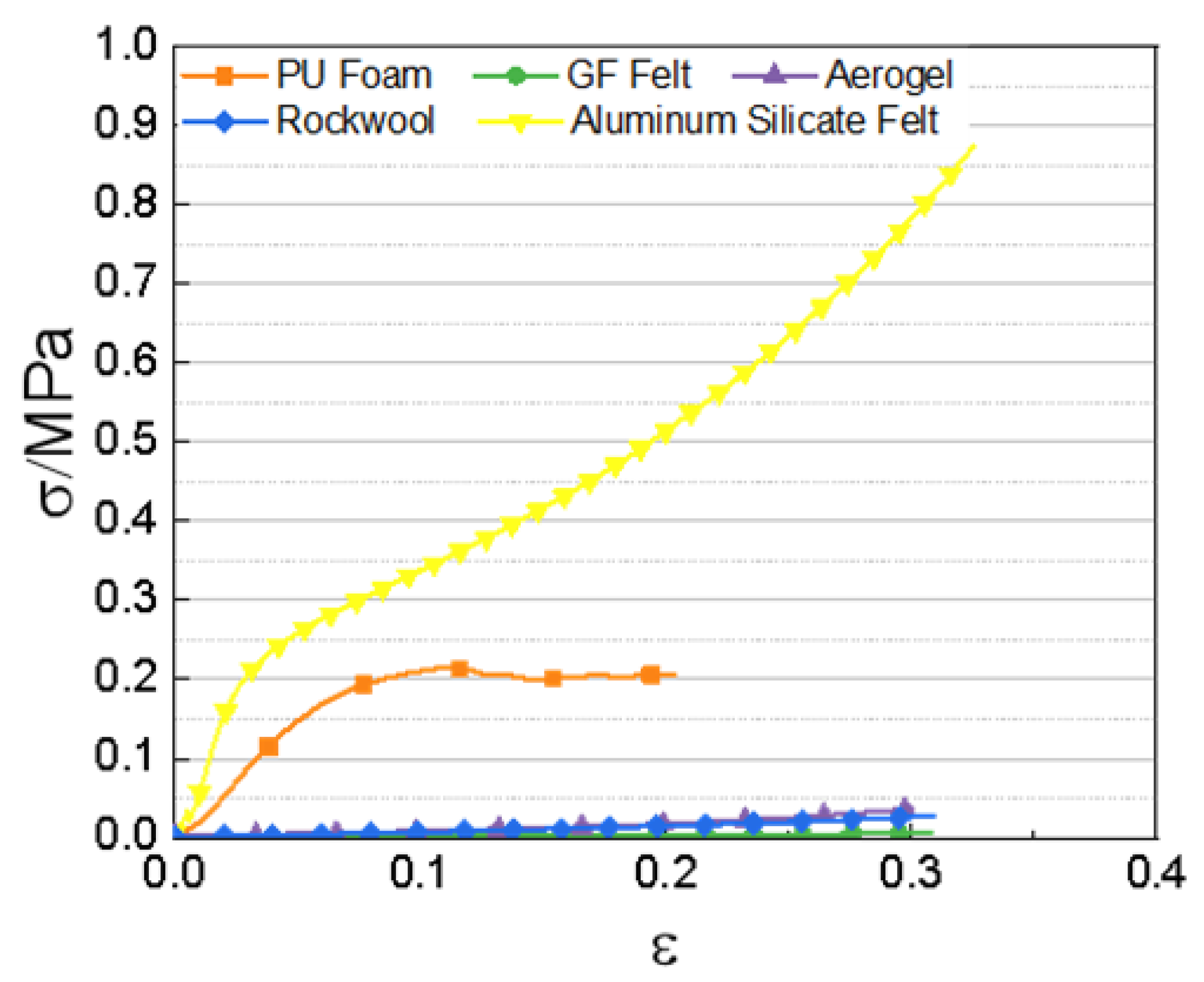
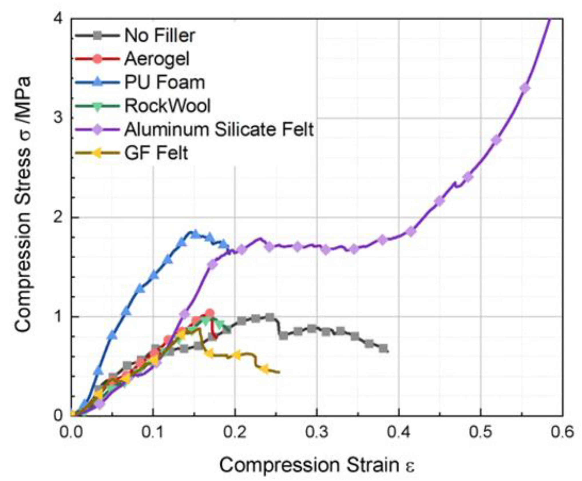
3.3. Mechanical Properties

The mechanical properties of the unidirectional GF-reinforced polypropylene composite laminates, with a fiber mass score of 60%, are shown in Table 5.
Stress-strain curve of different filler material can be seen in Figure 5. The compression of the GF felt, aerogel felt, and rock wool led to continuous densification of the material. During loading, the strain gradually increased, the actual volume decreased, the apparent density of the material continued to increase, and the modulus continued to increase with increasing density. As a result of the small deformation of the corrugated cavity during the compression performance testing of the corrugated sandwich panel, the density of the filled core material could be approximated as a constant. Therefore, the modulus in Table 6 corresponds to the density of the material filled in the corrugated core and represents the sample that has reached the filling density, the corresponding stress when the deformation is 10%, and the corresponding stress when the deformation of the specimen that has reached the filling density is 20%.
We filled the ripple sandwich panel with different materials to obtain the flat pressure stress–strain curves.
Figure 6 shows the stress–strain curves of the corrugated sandwich panels filled with different insulation materials under flat pressure loads. The stress–strain curves of the unfilled, GF felt, aerogel, and rock wool corrugated plates are not significantly different. Further, the soft insulation material itself exhibits poor mechanical properties, which can explain its non-contribution toward enhancing the flat pressure of the corrugated sandwich structure. The flattening performances of the polyurethane foam and aluminum silicate plate-filled corrugated sandwich panel were significantly improved. The slope of the elastic stage of the polyurethane foam filled corrugated sandwich panel in the corrugated cavity has fully filled the cavity, bearing part of the stress of the elastic compression stage, and the flat modulus and flat pressure strength have been significantly improved. The mechanical properties of the aluminum silicate fiber plate were the best among all filling materials, however, the modulus of the corrugated sandwich board with this material did not significantly improve in the initial stage of flattening. As there was a certain dimensional error between the trapezoidal filling and corrugated core of the aluminum silicate fiberboard, the contact surface was not fully fitted. Therefore, in the initial stage of loading, the aluminum silicate fiberboard filling did not play a load-bearing role, and the stress–strain curve of the corrugated sandwich plate with this material at the beginning of loading was similar to that of the untreated corrugated sandwich panel. With gradual compaction during loading, the aluminum silicate fiberboard and the composite corrugated skeleton jointly bore the compression load, and the overall modulus of the structure was significantly improved. In a manner different from that for the polyurethane foam corrugated sandwich panel, after reaching the stress peak, the stress–strain curve decreased slightly after a plateau period, and increased again. At this time, the corrugated skeleton load-bearing structure was destroyed, but the aluminum silicate fiberboard filling material was different from polyurethane foam. There is no crushing situation after the destruction of the composite corrugated skeleton, it can continue to bear the force. The modulus of the second half of the stress–strain curve was approximately equal to the deformation of the aluminum silicate fiber and deformation of the plate itself.

4. Conclusions

After a series of comparative test experiments, it can be concluded that the overall effective thermal conductivity of the prepared corrugated sandwich panel decreased with an increase in the ripple inclination and bond length b, and increased with the thickness of the panel; nevertheless, the degree of change is not large. It decreased with an increase in the corrugated height. When the height is increased to 15 mm, the impact of the change in the corrugated height was no longer evident. The two parameters that had the greatest impact were the thickness of the corrugated core and thermal conductivity of the filled material, which increased rapidly with the increase in the sum. Determining the two structural parameters that have the greatest influence on the heat transfer performance of corrugated sandwich panels has important guiding significance for the structural design of corrugated panels.

Author Contributions

Conceptualization, J.L. and B.Z.; methodology, Y.S. (Yixuan Song); software, Y.S. (Yixuan Song); validation, Y.S. (Yiliang Sun), J.L. and Y.S. (Yixuan Song); formal analysis, J.L.; investigation, Y.S. (Yixuan Song); resources, B.Z.; data curation, Y.S. (Yixuan Song); writing—original draft preparation, Y.S. (Yiliang Sun); writing—review and editing, Y.S. (Yiliang Sun); visualization, Y.S. (Yixuan Song); supervision, J.L.; project administration, H.L.; funding acquisition, B.Z. All authors have read and agreed to the published version of the manuscript.

Funding

This work was supported by Fundamental Research Funding (No. 514010104-302) and National Natural Science Foundation of China (Grant No. 11872086).

Institutional Review Board Statement

The study was conducted in accordance with the Declaration of Helsinki, and approved by the Institutional Review Board.

Informed Consent Statement

Informed consent was obtained from all subjects involved in the study.

Data Availability Statement

Not applicable.

Conflicts of Interest

The authors declare no conflict of interest.

References

  1. Birman, V.; Kardomateas, G.A. Review of current trends in research and applications of sandwich structures. Compos. Part B Eng. 2018, 142, 221–240. [Google Scholar] [CrossRef]
  2. Castanie, B.; Bouvet, C.; Ginot, M. Review of composite sandwich structure in aeronautic applications. Compos. Part C Open Access 2020, 1, 100004. [Google Scholar] [CrossRef]
  3. Lurie, S.; Solyaev, Y.; Volkov-Bogorodskiy, D.; Bouznik, V.; Koshurina, A. Design of the corrugated-core sandwich panel for the arctic rescue vehicle. Compos. Struct. 2017, 160, 1007–1019. [Google Scholar] [CrossRef]
  4. Rejab, M.R.M.; Cantwell, W.J. The mechanical behaviour of corrugated-core sandwich panels. Compos. Part B Eng. 2013, 47, 267–277. [Google Scholar] [CrossRef]
  5. Ai, S.; Wang, X.; Chen, Y.; Xu, B. Structural efficiency of a stitched integrated thermal protection system with thermal protection/insulation and load-bearing capacity. Compos. Struct. 2022, 298, 116073. [Google Scholar] [CrossRef]
  6. Li, W.; Zhang, Z.; Jiang, Z.; Zhu, M.; Zhang, J.; Huang, H.; Liang, J. Comprehensive performance of multifunctional lightweight composite reinforced with integrated preform for thermal protection system exposed to extreme environment. Aerosp. Sci. Technol. 2022, 126, 107647. [Google Scholar] [CrossRef]
  7. Li, Y.; Zhang, L.; He, R.; Ma, Y.; Zhang, K.; Bai, X.; Xu, B.; Chen, Y. IIntegrated thermal protection system based on C/SiC composite corrugated core sandwich plane structure. Aerosp. Sci. Technol. 2019, 91, 607–616. [Google Scholar] [CrossRef]
  8. Meng, S.; Yang, Q.; Xie, W.; Han, G.; Du, S. Structure Redesign of the Integrated Thermal Protection System and Fuzzy Performance Evaluation. AIAA J. 2016, 54, 3598–3607. [Google Scholar] [CrossRef]
  9. Gogu, C.; Bapanapalli, S.K.; Haftka, R.T.; Sankar, B. Comparison of Materials for an Integrated Thermal Protection System for Spacecraft Reentry. J. Spacecr. Rocket. 2009, 46, 501–513. [Google Scholar] [CrossRef]
  10. Wei, K.; He, R.; Cheng, X.; Zhang, R.; Pei, Y.; Fang, D. Fabrication and mechanical properties of lightweight ZrO2 ceramic corrugated core sandwich panels. Mater. Des. 2014, 64, 91–95. [Google Scholar] [CrossRef]
  11. Xie, G.; Wang, Q.; Sunden, B.; Zhang, W. Thermomechanical optimization of lightweight thermal protection system under aerodynamic heating. Appl. Therm. Eng. 2013, 59, 425–434. [Google Scholar] [CrossRef]
  12. Chen, T.; Cheng, S.; Jin, L.; Xu, T.; Zeng, T. Fabrication process and mechanical properties of C/SiC corrugated core sandwich panel. Ceram. Int. 2021, 47, 3634–3642. [Google Scholar] [CrossRef]
  13. He, J. Mechanical Properties of High Temperature Resistant Energy Storage Dielectric Materials and Radiation Scintillation Detection Composite Materials in Bridge Construction. Integr. Ferroelectr. 2022, 228, 51–66. [Google Scholar] [CrossRef]
  14. Li, Y.-M.; Deng, C.; Wang, Y.-Z. A novel high-temperature-resistant polymeric material for cables and insulated wires via the ceramization of mica-based ceramifiable EVA composites. Compos. Sci. Technol. 2016, 132, 116–122. [Google Scholar] [CrossRef]
  15. Liu, Z.; Wei, K.; Wang, S.; Ma, B.; Wang, X.; Shi, W.; Xu, J. Effect of high-temperature-resistant epoxy resin/polyethylene glycol 2000 composite stereotyped phase change material particles on asphalt properties. Constr. Build. Mater. 2021, 300, 124007. [Google Scholar] [CrossRef]
  16. Zhu, F.L.; Zhang, W.Y. Development of a Thermal-Electric Analog Method to Measure Thermal Conductivity of High Performance and High Temperature Resistant Materzials. In Proceedings of the International Conference on Advanced Fibers and Polymer Materials (ICAFPM 2005), Shanghai, China, 19–21 October 2005. [Google Scholar]
Figure 1. (a). GF/PP prepreg (b). Corrugated mold (c). Corrugated core material after hot compression molding.
Coatings 12 01719 g001
Figure 2. Schematic diagram of the molding process of thermoplastic corrugated sandwich panel.
Coatings 12 01719 g002
Figure 4. Different kinds of mechanical test specimens.
Coatings 12 01719 g004
Figure 5. Stress-strain curve of different filler material.
Coatings 12 01719 g005
Figure 6. Different filling material corrugated sandwich plate flat pressure stress-strain curve.
Coatings 12 01719 g006
Table 1. Experimental materials.
Raw MaterialsSuppliersProduct Grade
Unidirectional glass fiber polypropylene prepregJun er (Wenzhou, China)GF60
Rigid polyurethane foamYanji (Nanjing, China)F193
Glass fiber feltNavigator (Shanghai, China)Blm001
AerogelTaoge (Langfang City, China)180KG/M3
Rockwool Huafeng (Jiaxing, China)YMB-50
Aluminum silicate fiberHuafeng (Jiaxing, China)50 mm Standard beam
Aluminum foil tapeBangte (Jiangyin, China)50 mm width
Table 2. Test device information.
Test EquipmentProducerEquipment Model
Low temperature plate thermal conductivity meterDazhan (Nanjing, China)DZDR-PL
Low temperature synchronous thermal analyzerNetzsch (Berlin, Germany)STA449F3
Flash thermal conductivityNetzsch (Berlin, Germany)LFA457
Flat plate press Shenghua (Nanjing, China)XLB-L500*500
Electronic universal testing machineKexin (Changchun, China)WDW-100
Precision digital display pressure gaugeHaogan (Shanghai, China)HG-806XB
Electronic balancesYueping (Shanghai, China)FA2004B
Engraving machineJingyan (Dongguan, China)CNC4030
Table 3. Comparison of thermal insulation properties of different materials.
Raw MaterialsTest Value
W·m−1·K−1
Parameters Provided by Vendors
W·m−1·K−1
Test MethodStandard
Aerogel0.024 0.018steady-state plateISO 8302:1991
GF felt0.044 0.028–0.043steady-state plateISO 8302:1991
PU foam0.030 0.028–0.044steady-state plateISO 8302:1991
Rockwool 0.0880.082steady-state plateISO 8302:1991
Al-Si felt0.1180.137steady-state plateISO 8302:1991
Unidirectional GF/PP (axial)0.779-laser flashASTM E1461-13
Unidirectional GF/PP (radical)0.434ASTM E1461-13
Table 4. The effective thermal conductivity of corrugated sandwich panels with different filling materials.
Core MaterialsTheoretical Calculation ValueExperimental ValueRelative Error
Air0.1920.15917%
Glass fiber felt0.0810.05235%
Aerogel0.0590.04031%
PU foam0.0660.04728%
Rockwool0.1270.11411%
Aluminum silicate fiber0.1570.14210%
Table 5. The Mechanical properties of GF/PP laminate.
PerformanceGF/PP Laminate
Poisson’s ratio0.28
0° Modulus/GPa24.8
90° Modulus/GPa2.84
Shear modulus/GPa1.3
0° Tensile strength/MPa732.6
0° Compression strength/MPa153.3
90° Tensile strength/MPa13.6
90° Compression strength/MPa45.7
Shear strength/MPa22.2
Table 6. Performance comparison of raw materials.
Raw MaterialsModulus
MPa
δc
MPa
δ10
MPa
δ20
MPa
Density
g/cm3
Aerogel0.064-0.00840.01780.163
GF felt0.030-0.00570.01430.105
PU foam2.8400.215--0.110
Rockwool0.068-0.0160.430.107
Al-Si Felt10.9700.237--0.287
Publisher’s Note: MDPI stays neutral with regard to jurisdictional claims in published maps and institutional affiliations.

