Article

Development of a Kelp-Type Structure Module in a Coastal Ocean Model to Assess the Hydrodynamic Impact of Seawater Uranium Extraction Technology

Coastal Sciences Division, Pacific Northwest National Laboratory, 1529 W. Sequim Bay Road, Sequim, WA 98382, USA
*
Author to whom correspondence should be addressed.
J. Mar. Sci. Eng. 2014, 2(1), 81-92; https://doi.org/10.3390/jmse2010081
Submission received: 12 December 2013 / Revised: 17 January 2014 / Accepted: 20 January 2014 / Published: 7 February 2014

Abstract

:
With the rapid growth of global energy demand, interest in extracting uranium from seawater for nuclear energy has been renewed. While extracting seawater uranium is not yet commercially viable, it serves as a “backstop” to the conventional uranium resources and provides an essentially unlimited supply of uranium resource. With recent technology advances, extracting uranium from seawater could be economically feasible only when the extraction devices are deployed at a large scale (e.g., several hundred km2). There is concern however that the large scale deployment of adsorbent farms could result in potential impacts to the hydrodynamic flow field in an oceanic setting. In this study, a kelp-type structure module based on the classic momentum sink approach was incorporated into a coastal ocean model to simulate the blockage effect of a farm of passive uranium extraction devices on the flow field. The module was quantitatively validated against laboratory flume experiments for both velocity and turbulence profiles.Model results suggest that the reduction in ambient currents could range from 4% to 10% using adsorbent farm dimensions and mooring densities previously described in the literature and with typical drag coefficients.

1. Introduction

Uranium fuels more than 400 nuclear reactors worldwide and provides over 13% of the world’s electricity. While uranium is among the most abundant elements found in natural crustal rock, it is seldom sufficiently concentrated to be economically recoverable. The uranium ore in the ground has remained as the single most important conventional uranium resource. Based on current consumption rates, the known uranium ore resources that can be mined at current costs are estimated to be sufficient to produce fuel for about a century. Although at low concentrations, the world oceans hold the largest reserves of uranium. In fact, extracting metals (e.g., Na, Mg, and K) from seawater has been commercialized for a long time [1]. The possibility of recovery of seawater uranium by ion-exchange resins was studied shortly after World War II, but was not economically viable compared to exploitation of known uranium ores on land [2]. While extracting seawater uranium is not yet commercially viable, it serves as a “backstop” to the conventional uranium resources and provides an essentially unlimited (~6500 years) supply of uranium [3]. Driven by the rapid growth of global energy demand in recent decades, interest in extracting uranium from seawater for nuclear energy has been renewed. With recent advances in seawater uranium extraction technology, extracting uranium from seawater could become economically feasible especially when the extraction devices are deployed at large scales of several hundred km2 [4].
Sugo et al. [5] introduced the braided adsorbent farm technology that is potentially feasible for large-scale uranium extraction from seawater. The fibers are braided around a low-density core to result in positively-buoyant braids approximately 60 meters in length. The material is carried to the deployment site and moored to the ocean floor with anchor chains. The proposed design calls for deployment of over a million long braided moorings, 60 m in height over an area of about 680 km2. The submerged farm closely resembles a kelp forest, which is known to exert a substantial drag on coastal currents [6]. Hence, there is concern that the large scale deployment of adsorbent farms could result in potential impact to the hydrodynamic flow field in an oceanic setting.
In this study, a kelp-type structure module was incorporated into the Finite Volume Coastal Ocean Model (FVCOM) to simulate the retardation effect of a farm of uranium extraction devices on the flow field. The kelp-type structure module is based on the classic momentum sink approach that approximates the blockage effect of structures on flows as additional drag force in the momentum equations. This paper summarizes the kelp-type module development and validation processes.

2. Methodology

2.1. Kelp-Type Structure Module Development

A number of modeling studies have been carried out to investigate the hydrodynamic effects of underwater structures, including aquaculture farms, vegetation canopies, as well as wind and tidal energy farms. For instance, Grant and Bacher [7] developed a two-dimensional (2-D) finite element circulation model for Sungo Bay, China to study the effect of bivalve culture structure on flows. The drag exerted by the culture drop ropes was parameterized as additional form drag in the hydrodynamic model, which predicted a 54% reduction in current speed in the midst of the culture area. By approximating the shellfish farm drag as additional bottom friction in a 2-D hydrodynamic model, Plew [8] studied the shellfish farm-induced changes to tidal circulation in an embayment in New Zealand, and found that the current speeds were reduced inside most farms. Struve et al. [9] studied the influence of model mangrove trees on the hydrodynamics in a flume through both flume experiments and 2-D depth-integrated numerical modeling. The model results compared very well with experiment measurements when the resistance created by mangroves was modeled as an additional drag force. Hence, in this study, a similar momentum sink approach was adopted for the kelp-type structure module to assess the hydrodynamic impact of seawater uranium extraction devices. Specifically, the additional resistance force on flow caused by a single uranium adsorbent braid or kelp frond is defined as:
Jmse 02 00081 i001
where τ additional resistance force by uranium adsorbent braid (N), ρ = seawater density (kg/m3), Cd = drag coefficient of the equivalent (cylindrical) braid or kelp structure, A = flow-facing area of the adsorbent braid or kelp frond (m2), A = diameter × length for cylinders, and Jmse 02 00081 i011 = velocity vector (m/s).
The hydrodynamic model selected in this study is the finite volume coastal ocean model FVCOM developed by Chen et al. [10]. As a three-dimensional (3-D) unstructured-grid coastal ocean model, FVCOM is capable of simulating water surface elevation, velocity, temperature, salinity, sediment, and water quality constituents. The unstructured grid and finite volume approach employed in the model provides geometric flexibility and mass conservation that is well suited to simulate hydrodynamic transport at various spatial scales within a large model domain. For computational efficiency, a mode splitting scheme is used to solve the momentum equations. FVCOM has been extensively used by the estuarine and coastal modeling community to study a variety of scientific and engineering problems in estuaries and coastal oceans [11,12,13]. The numerical aspects and detailed formulations of FVCOM have been presented in Chen et al. [10,14] and many other FVCOM publications, thus they will not be elaborated here except for the portions in the momentum governing equations that were modified to include the momentum sink induced by underwater structures.
The modified FVCOM momentum equations in the horizontal directions have the following general form [13]:
Jmse 02 00081 i002
Jmse 02 00081 i003
where (x, y, z) are the east, north, and vertical axes in the Cartesian coordinates; (u, v, w) are the three velocity components in the x, y, and z directions, respectively; (Fx, Fv) are the horizontal momentum diffusivity terms in the x and y directions, respectively; Km is the vertical eddy viscosity coefficient; ρ is water density; p is pressure; and f is the Coriolis parameter. FxM and fyM are the momentum sink term (m/s2) induced by the uranium adsorbent device that was added to the original FVCOM governing equations [10,14], and is defined as the following general form:
Jmse 02 00081 i004
where Vc = momentum control volume in which the adsorbent device is deployed (m3), N = the number of adsorbent braids deployed within the same momentum control volume, and the rest terms were defined previously in Equation (1).
FVCOM solves the momentum equations using the finite-volume method and sigma-stretched coordinate transformation in the vertical direction. Assuming one adsorbent braid may occupy multiple σ-layers and is located within a single momentum control element (i.e., the model grid size is much larger than the width of adsorbent braid), the integrated form of Equations (2) and (3) for the 3-D internal mode can be written as:
Jmse 02 00081 i005
Jmse 02 00081 i006
where Ae = triangular element surface area (m2), ΔσD = σ-layer thickness (m), Ru and Rv = all the remaining momentum terms including advection, diffusion, and pressure gradient. The right hand side of Equations (5) and (6) represents the volumetric momentum sink rate (m4/s2) contributed by the adsorbent braid or kelp frond defined in Equation (1), and Aσ = flow-facing area of braid adsorbent within the σ-layer.
The integrated form for the 2-D external mode of Equations (2) and (3) are expressed as:
Jmse 02 00081 i007
Jmse 02 00081 i008
where u and v = vertically averaged velocity in the x and y directions, respectively.

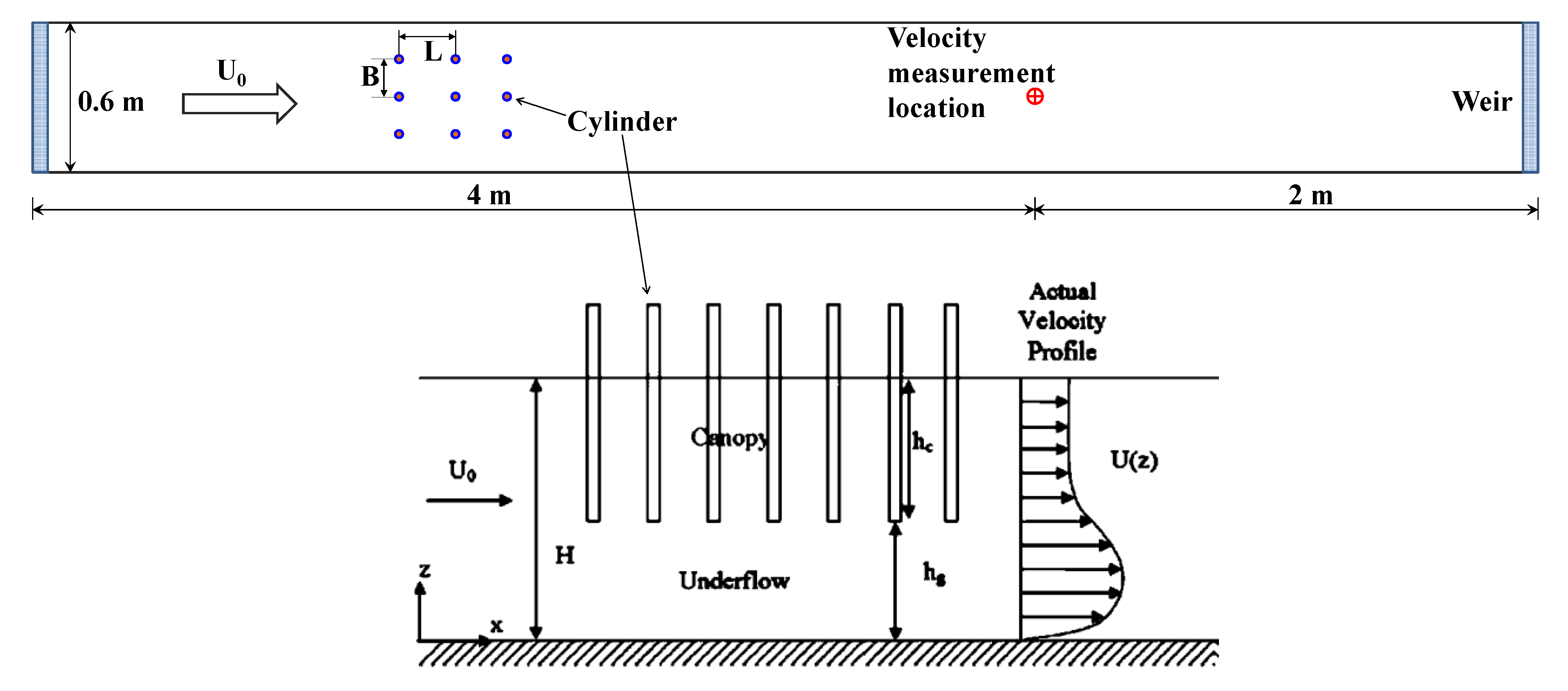
2.2. Module Validation

The kelp-type structure module was validated against laboratory experiments conducted by Plew [15]. The detailed experiment configuration has been described in Plew [15], and is briefly presented here. The experiments were conducted in a 6-m long by 0.6-m wide flume (Figure 1). The structure canopies were constructed from aluminum cylinders of 9.54-mm diameter, and extended over the full width and the entire working length (4.8 m) of the flume. The velocity profiles were measured using particle tracking velocimetry (PTV) at a distance of 4 m from the flow inlet. Velocity measurements were made in two vertical planes, mid-way between cylinders and then in line with the cylinders, and were averaged horizontally in the x-direction over the distance (L) between cylinder rows to give an averaged vertical profiles for each plane. This enabled a vertical profile of spatially averaged velocity and turbulence statistics to be defined.
Figure 1. Schematic of the experimental flume setup (adapted from Plew [15], with permission from © 2011 American Society of Civil Engineers). Cylinders were arranged in rows with a spacing of L (m) in the direction of flow, and a transverse spacing of B (m) between cylinders. Velocity measurements were taken at a distance of 4 m from the inlet. H (m) is the total water depth in the flume, hc (m) is the canopy height, and hg (m) is the distance between the canopy and the flume bed.
Jmse 02 00081 g001
Table 1 summarizes the configuration of the four flume experiments selected for the kelp-type module validation in this study. The cylinders were suspended in the upper half of the water column in all the experiments but with different horizontal spacing/density, allowing cylinder density to increase from runs A to D.
Table 1. Summary of flume experiments selected from Plew [15] for kelp-type module validation. a is the projected cylinder flow-facing area per unit volume inside the canopy, and Q is the flow rate (data obtained from Plew [15]).
Validation RunH (mm)hg (mm)L (mm)B (mm)a (m−1)Q (L/s)
A200100100501.90810.5
B200100150501.27210.1
C200100200500.95410.1
D2001002001000.47710.3
FVCOM was configured based on the flume experiment configurations listed in Figure 1 and Table 1 to validate the kelp-type structure module. The flume was represented with an unstructured mesh consisting of 5578 elements and 2954 nodes in the horizontal plane (Figure 2a). In the vertical direction, 40 uniform sigma layers were specified. An external time-step of 0.001 second was used in all model runs. The default Mellor-Yamada 2.5 turbulence closure was used for vertical eddy viscosity and diffusivity calculations. The drag coefficient (Cd) of the canopy was treated as spatially uniform but its value for each validation run was calibrated based on model-data comparisons. Figure 2b shows the spatial distribution of the cylinder array in Validation Run D. The corresponding model predicted surface velocity field during the baseline condition (without cylinder array) and Run D are presented in Figure 2c,d, respectively. The presence of cylinders significantly altered the flow field. Surface velocity was generally reduced within the cylinder canopy compared to the baseline condition.
Figure 2. (a) Finite Volume Coastal Ocean Model (FVCOM) model grid (in the horizontal plane) for the flume experiment. (b) Spatial distribution of cylinders in Run D. (c) Surface velocity field in the baseline condition without the cylinder array. (d) Surface velocity field in Run D.
Jmse 02 00081 g002

3. Results and Discussion

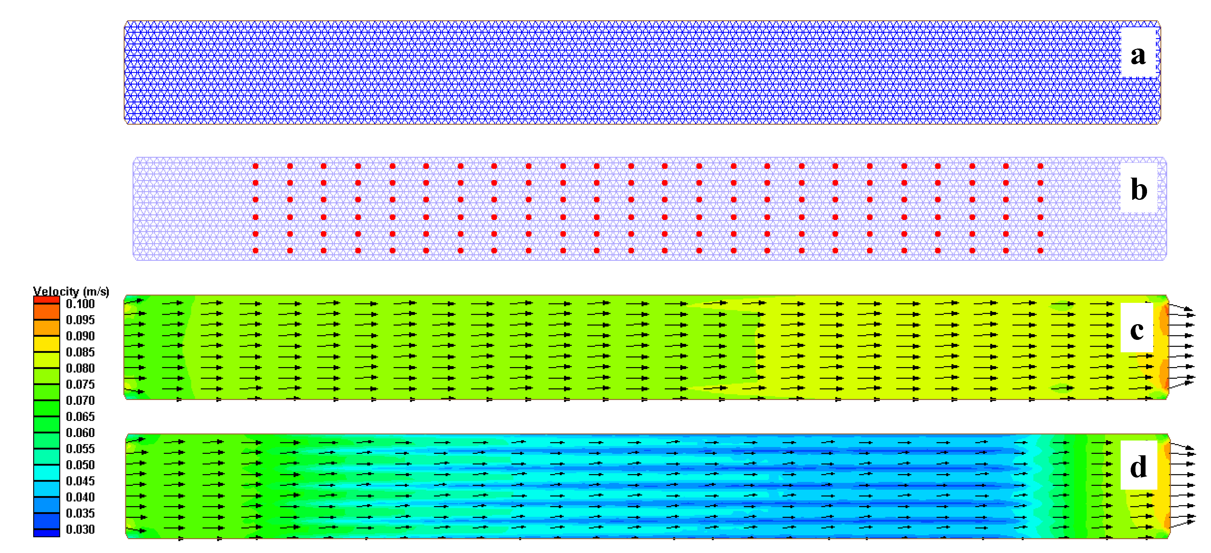
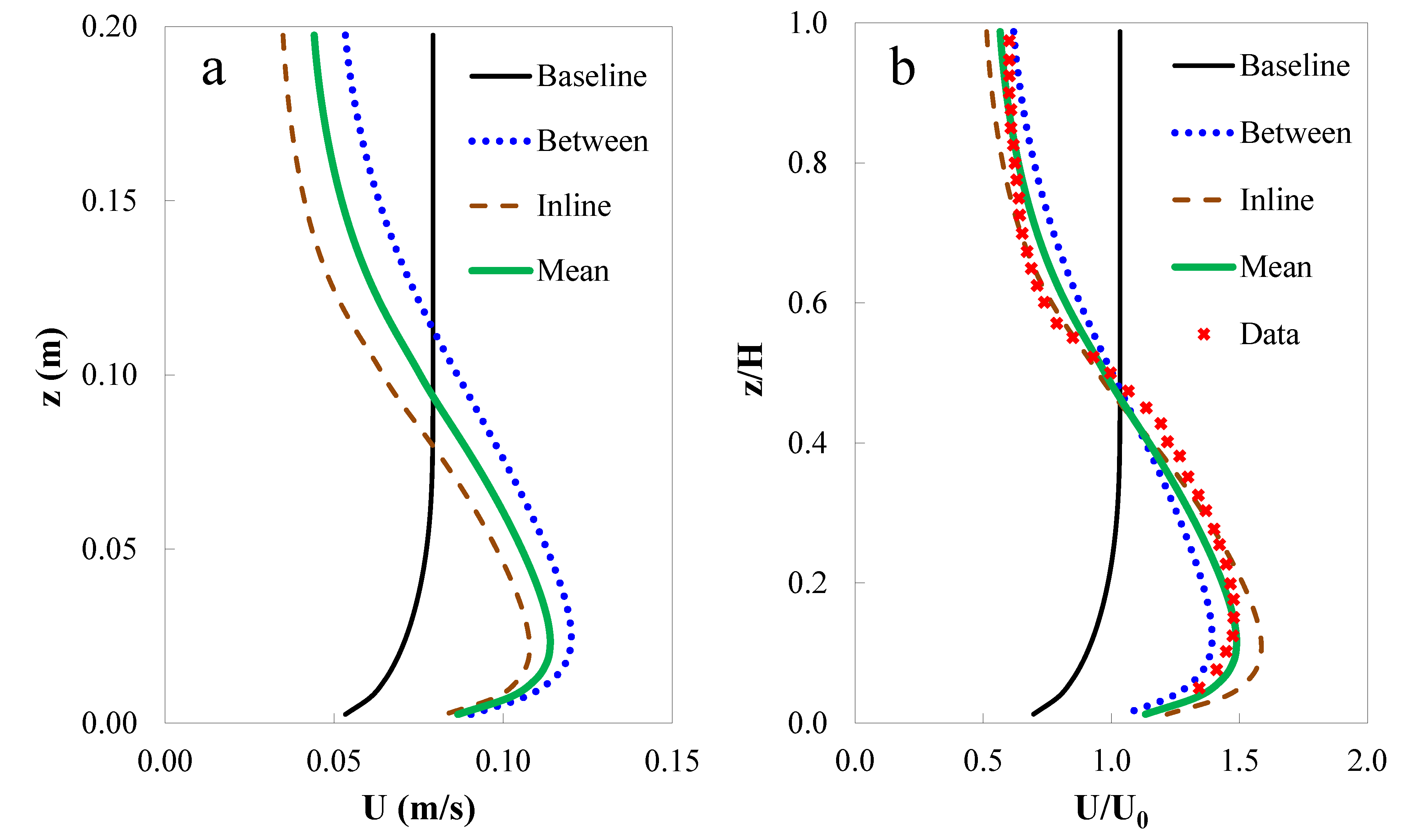
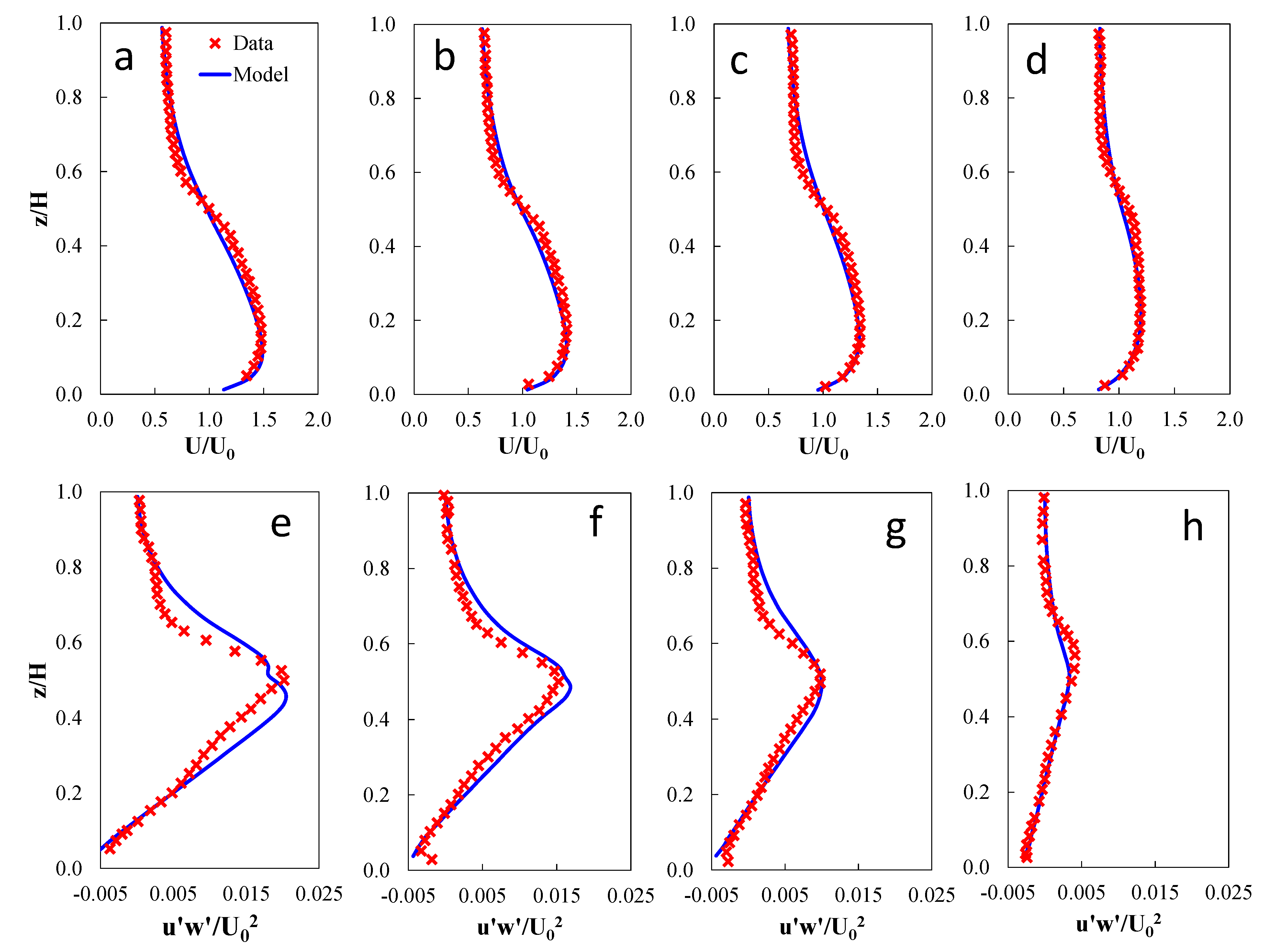
3.1. Kelp-Type Module Validation

The model predicted velocity and turbulent stress profiles were compared with laboratory data digitized from Plew [15]. Figure 3a shows the model predicted vertical velocity profiles for Validation Run A which has the highest cylinder density among all the runs. In general, the velocity profiles with cylinders showed a significant change from that of the baseline condition with no cylinders present. Flows were reduced within the canopy while increased beneath the canopy. As expected, the change to flow structure is more significant for flows in-line with the cylinder arrays than between arrays. Figure 3b shows the corresponding model-data comparison of the normalized (by mean free-stream) velocity profiles. The model predicted mean velocity profile agrees with the laboratory measurements reasonably well. A drag coefficient (Cd) of 1.75 was found to provide good model-data comparison in this validation run.
Figure 3. (a) FVCOM predicted vertical velocity profiles for Validation Run A. (b) Normalized velocity profiles for validation Run A compared to the experimental measurements.
Jmse 02 00081 g003
The model-data comparisons for all four validation runs are presented in Figure 4, and the corresponding error statistics are listed in Table 2. The model results have been normalized/non-dimensionalized so that they can be directly compared with laboratory data presented in Plew [15]. While the velocity profiles can be directly extracted from the model output, the turbulent stress was calculated using (9):
Jmse 02 00081 i009
where u′w′ = turbulent stress (m2/s2), and Km = vertical eddy viscosity (m2/s).
Table 2. Error statistics for kelp-type structure module validation runs (R2 denotes the coefficient of determination and RE stands for relative error defined by Jmse 02 00081 i010, where ηm and η° stand for model predictions and laboratory observations, respectively, ηo is the mean of observations).
Validation RunVelocityTurbulent Stress
R2RE (%)R2RE (%)
A0.981.20.946.0
B0.981.40.983.6
C0.981.70.945.5
D0.972.50.935.0
Figure 4. (ad) Model-data comparisons of normalized mean vertical velocity profiles for Validation Runs A, B, C, and D, respectively. (eh) Model-data comparisons of normalized mean turbulent stress profiles for Validation Runs A, B, C, and D, respectively.
Jmse 02 00081 g004
There is an overall good agreement between model predictions and direct measurements for all the validation runs (Figure 4). The good model-data comparison is further confirmed by error statistics which show a high coefficient of determination (R2) and low relative error (RE) between predicted and measured velocity and turbulent stress values (Table 2). In general, the model captures the vertical structure for both velocity and turbulent stress. For instance, the velocities were significantly attenuated for flows through the cylinders and the maximum turbulence was generated near the middle depth of the water column at the interface between the bottom of the cylinder canopy and the flow immediately below. In addition, as evident from model predictions and laboratory data, higher cylinder density (Parameter a in Table 1) tends to exert a stronger impact on flows. The maximum differences between the model and data occurred in the middle depths of the water column. A better parameterization may be needed at canopy-water interfaces to account for this difference. For example, additional skin friction contributed by the bottom of the cylinder may be considered. This discrepancy could also be contributed by the inadequate characterization of the canopy’s effects on turbulence in the current module, as suggested by other studies [16,17].
The model results also indicated that the drag coefficient (Cd) is a function of canopy density and increases with higher density. For example, the calibrated Cd values for Runs A, B, C and D are 1.75, 1.5, 1.25, and 1.0, respectively. This is also consistent with the findings in other similar studies [9,15,18]. Wu and Wang [18] and Struve et al. [9] reported that Cd values greater than 3.0 were needed to reach a good agreement between model and data. As discussed by Wu and Wang [18], this is presumably due to the inherent dependency of Cd on the Reynolds number (Re). At higher canopy densities, reduced flow velocity and Reynolds number in the model domain lead to larger drag coefficients according to the relationship between Cd and Re for a single cylinder [19]. The validation tests also suggest this. Although the actual Cd values varied with canopy density, a spatially uniform Cd represented the major conditions reasonably well.

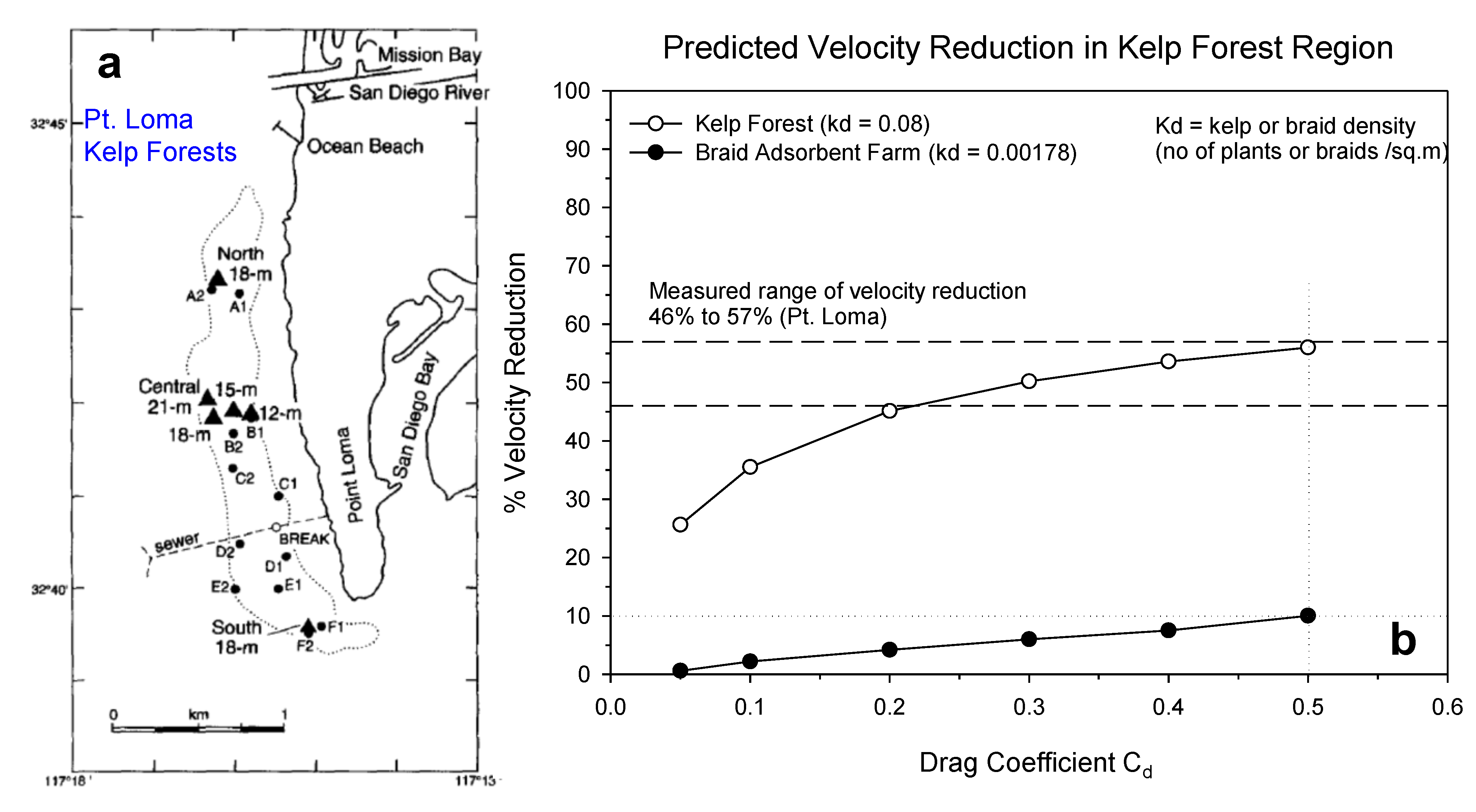
3.2. Module Applications—Kelp Forest and Braid Adsorbent Farm Simulation

The validated kelp-type structure module was used to simulate the effects of a kelp forest and uranium braid adsorbent farm on coastal flows. Numerous studies have documented the effects of kelp forest on coastal currents. The current measurements conducted by Jackson [6] off the coast of California in the Point Loma kelp forest were selected as the reference for kelp forest simulation in this study. The oceanographic conditions including 7-km-long and 1-km-wide stretch of real kelp forest were setup in the FVCOM model. The kelp fronds were 0.2 m in diameter and occupied the full 15 m of water depth. The model grid used was a simplified rectangular channel which carried a mean longshore ambient current of 2 cm/s reproducing the conditions observed during the field survey. The kelp density (Kd) used for this numerical experiment was 0.08 fronds/m2, which is the average of the observed kelp density range of 0.02 to 0.14 fronds/m2.
The model results for the Point Loma kelp forest shown in Figure 5 suggest that the drag provided by kelp forest results in a reduction of ambient currents from 45% to 55% for typical drag coefficient values ranging from 0.2 to 0.5. This is consistent with field observations that indicated a significant reduction in longshore currents with dense kelp forest [6,20,21]. Moreover, this prediction serves as an additional qualitative model validation study.
The kelp forest in the above model configuration was substituted with braid adsorbent moorings to estimate if a braid adsorbent farm for seawater uranium extraction would have a similar effect. The physical dimensions of the moorings were set identical to the kelp fronds (0.2 m diameter and 15 m long occupying the full water column). The proposed braid adsorbent farm design calls for moorings on 8 m × 70 m centers. This corresponds to an adsorbent mooring density (Kd) of 0.00178 moorings/m2, much less dense than the kelp forest (0.08 fronds/m2). The model results suggest that with typical drag coefficient values of 0.2 to 0.5, the reduction in ambient currents by braid adsorbent farms could range from 4% to 10%.
Figure 5. (a) Map of the Point Loma kelp forest offshore of the California coast. The dotted line represents a general outline of the kelp canopy (map adapted from Tegner et al. [22] with permission from Elsevier). (b) Predicted potential reductions in ambient currents by the kelp forest and braid adsorbent farm with typical canopy/mooring densities.
Jmse 02 00081 g005

4. Conclusions

A kelp-type structure module was incorporated into the coastal ocean model FVCOM based on the commonly used momentum sink approach in which the resistance force exerted by kelp-type structures is parameterized as additional form drag in the momentum equations. The module was reasonably validated using observations from both laboratory flume experiments and field surveys conducted in the kelp forest near Pt. Loma off the Californian coast. Model results suggest that the reduction in ambient currents could range from 4% to 10% for a farm of uranium adsorbent material having configurations for mooring density described previously by Japanese scientists [5] and employing a typical drag coefficient. This study demonstrates that a momentum sink approach based on structure module is capable of characterizing the general hydrodynamic impact of kelp-type structures on coastal flows. Improvements in the current module could be made by including other processes such as the effect of canopy on turbulence [16,17,23] and calibrated drag coefficients by braid adsorbents.

Acknowledgments

This work was funded by the Office of Nuclear Energy, U.S. Department of Energy. The authors also thank David Plew for providing additional information on the flume experiment configurations.

Conflicts of Interest

The authors declare no conflict of interest.

References

  1. Bardi, U. Extracting minerals from seawater: An energy analysis. Sustainability 2010, 2, 980–992. [Google Scholar] [CrossRef]
  2. Davies, R.V.; Kennedy, J.; McIlroy, R.W.; Spence, R.; Hill, K.M. Extraction of uranium from sea water. Nature 1964, 203, 1110–1115. [Google Scholar] [CrossRef]
  3. Annual Report: Powerful Partnerships: The Federal Role in International Cooperation on Energy Innovation; Office of the President of the United States: Washington, DC, USA, June 1999.
  4. Tamada, M.; Seko, N.; Kasai, N.; Shimizu, T. Cost estimation of uranium recovery from seawater with system of braid type adsorbent. Trans. Atomic Energy Soc. Jpn. 2006, 5, 358–363. [Google Scholar]
  5. Sugo, T.; Tamada, M.; Seguchi, T.; Shimizu, T.; Uotani, M.; Kashima, R. Recovery system for uranium from seawater with fibrous adsorbent and its preliminary cost estimation. J. Atomic Energy Soc. Jpn. 2001, 43, 1010–1016. [Google Scholar] [CrossRef]
  6. Jackson, G.A. Currents in the high drag environment of a coastal kelp stand off California. Cont. Shelf Res. 1998, 17, 1913–1928. [Google Scholar] [CrossRef]
  7. Grant, J.; Bacher, C. A numerical model of flow modification induced by suspended aquaculture in a Chinese Bay. Can. J. Fish. Aquat. Sci. 2001, 58, 1003–1011. [Google Scholar] [CrossRef]
  8. Plew, D.R. Shellfish farm-induced changes to tidal circulation in an embayment, and implications for seston depletion. Aquac. Environ. Interact. 2011, 1, 201–214. [Google Scholar] [CrossRef]
  9. Struve, J.; Falconer, R.A.; Wu, Y. Influence of model mangrove trees on the hydrodynamics in a flume. Estuar. Coast. Shelf Sci. 2003, 58, 163–171. [Google Scholar] [CrossRef]
  10. Chen, C.; Liu, H.; Beardsley, R.C. An unstructured, finite-volume, three-dimensional, primitive equation ocean model: Application to coastal ocean and estuaries. J. Atmos. Ocean. Technol. 2003, 20, 159–186. [Google Scholar] [CrossRef]
  11. Chen, C.; Huang, H.; Beardsley, R.; Liu, H.; Xu, Q.; Cowles, G. A finite volume numerical approach for coastal ocean circulation studies: Comparisons with finite difference models. J. Geophys. Res. 2007, 112, C03018. [Google Scholar] [CrossRef]
  12. Ji, R.; Davis, C.; Chen, C.; Beardsley, R. Influence of local and external processes on the annual nitrogen cycle and primary productivity on Georges Bank: A 3-D biological-physical modeling study. J. Mar. Syst. 2008, 73, 31–47. [Google Scholar] [CrossRef]
  13. Yang, Z.; Wang, T.; Copping, A.E. Modeling tidal stream energy extraction and its effects on transport processes in a tidal channel and bay system using a three-dimensional coastal ocean model. Renew. Energy 2013, 50, 605–613. [Google Scholar] [CrossRef]
  14. Chen, C.; Beardsley, R.C.; Cowles, G. An Unstructured Grid, Finite-Volume Coastal Ocean Model: FVCOM User Manual; School for Marine Science and Technology, University of Massachusetts Dartmouth: North Dartmouth, MA, USA, 2006; p. 315. [Google Scholar]
  15. Plew, D.R. Depth-averaged drag coefficient for modeling flow through suspended canopies. J. Hydraul. Eng. 2011, 137, 234–247. [Google Scholar]
  16. Li, C.; Yan, K. Numerical investigation of wave-current-vegetation interaction. J. Hydraul. Eng. 2007, 133, 794–803. [Google Scholar] [CrossRef]
  17. Sheng, Y.P.; Lapetina, A.; Ma, G. The reduction of storm surge by vegetation canopies—three-dimensional simulations. Geophys. Res. Lett. 2012, 39, L20601. [Google Scholar] [CrossRef]
  18. Wu, W.; Wang, S.S.Y. A depth-averaged two-dimensional numerical model of flow and sediment transport in open channels with vegetation. In Riparian Vegetation and Fluvial Geomorphology; American Geophysical Union: Washington, DC, USA, 2004. [Google Scholar]
  19. Schlichting, H. Boundary Layer Theory; McGraw Hill Book Co.: New York, NY, USA, 1968. [Google Scholar]
  20. Jackson, G.A.; Winant, C.D. Effect of a kelp forest on coastal currents. Cont. Shelf Res. 1983, 20, 75–80. [Google Scholar] [CrossRef]
  21. Rosman, J.H.; Koseff, J.R.; Monismith, S.G.; Grover, J. A field investigation into the effects of a kelp forest (Macrocystis pyrifera) on coastal hydrodynamics and transport. J. Geophys. Res. 2007, 112, C02016. [Google Scholar] [CrossRef]
  22. Tegner, M.J.; Dayton, P.K.; Edwards, P.B.; Riser, K.L.; Chadwick, D.B.; Dean, T.A.; Deysher, L. Effects of a large sewage spill on a kelp forest community: Catastrophe or disturbance? Mar. Environ. Res. 1995, 40, 181–224. [Google Scholar]
  23. Katul, G.G.; Mahrt, L.; Poggi, D.; Sanz, C. One- and two-equation models for canopy turbulence. Bound. Layer Meteorol. 2004, 113, 81–109. [Google Scholar]

