1. Introduction
Fuel cells are potential power sources for future pollution-free applications. Polymer electrolyte membrane fuel cells (PEMFCs) are an important type of fuel cell for applications in portable devices, stationary and transport power supply. Perfluorosulfonic acid membranes, such as Nafion
®, are well-known commercial membranes for PEMFCs. However, there are issues with the use of PEMFCs such as relatively high cost (Nafion and Pt based catalysts) and operating temperature restrictions (<100 °C). These limitations have stimulated interest and commercialization in fuel cells at the intermediate temperature range of 100–400 °C [
1,
2]. These types of fuel cells offer several advantages such as [
3,
4,
5,
6,
7]:
- (1)
High CO tolerance and thus the ability to use less pure hydrogen fuels,
- (2)
Enhancement in efficiency,
- (3)
Avoidance of the cathode electrode flooding by water formed in the cell reaction between hydrogen and oxygen (Equation 1):
- (3)
(4) Potential to use non-noble metal catalyst,
- (3)
(5) System simplification through removal of humidification requirements and better cell heat transfer.
In the intermediate temperature range, several types of solid state electrolytes have been considered such as non-fluorinated polymers, pyrophosphates [
8] heteropolyacids and solid acids [
9]. In the lower end of this intermediate temperature range, (
i.e., 120–200 °C) polymer electrolytes loaded with phosphoric acid (PA) have been dominant. Such materials may reduce corrosion problems and improve PA immobilisation compared to its use in phosphoric acid fuel cells (PAFCs) [
7]. Polybenzimidazole (PBI) is the best known example of a membrane material used as a solid state electrolyte when loaded with phosphoric acid. Such membranes have been used for fuel cells providing high conductivity and good thermal and chemical resistance [
5].
Based on our previous work, quaternary diazabicyclo-octane polysulfone (QDPSU) was successfully synthesised and considered as a membrane for intermediate temperature fuel cells, giving a power density of 400 mW cm
−2 at 150 °C and atmospheric pressure [
10]. Several inorganic materials, such as TiO
2 [
11], caesium substitute heteropolyacids [
7] and graphite oxide [
12] have been combined with PBI to form composite membranes with enhanced conductivity.
Good mechanical strength is an important property for a membrane in fuel cells. Polytetrafluoroethylene (PTFE) is a material that can increase the mechanical strength of the membrane, as reported by Li
et al. with PA loaded PBI [
13]. Xing
et al. reported a montmorillonite/sulfonated poly (phenylether sulfone)/PTFE composite membrane that provided good strength because of the introduction of the PTFE microporous film [
14].
In many cases high loadings of phosphoric are used with PBI membranes to enhance conductivity [
5]. However excess phosphoric acid,
i.e., more than 2 per repeating unit (PRU), may result in a reduction in mechanical strength and elution problems of electrolytes [
12]. Especially above 100 °C, free acid may be lost with evaporated water which could result in instability. Ideally what is required is a membrane material that has high conductivity with a low acid loading and our approach was to use a composite of an inorganic oxide (conducting) with PBI. In this work, a Cs
XH
3−XPMo
12O
40 (CsPOMo)/quaternary diazabicyclo-octane polysulfone with polytetrafluoroethylene (QDPSU/PTFE) composite membrane was prepared with a low phosphoric acid loading to provide good proton conductivity and mechanical strength.
2. Results and Discussion
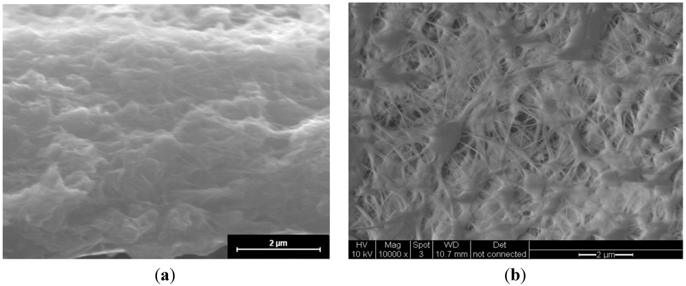
Figure 1 shows an image of the cross-section of the CsPOMo/PSU/PTFE/H
3PO
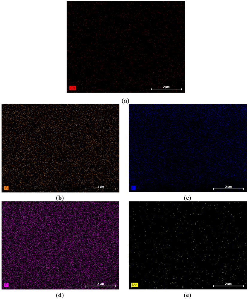
4 membrane. The dense structure of the composite membrane indicates that the pores of the PTFE membrane were filled with the CsPOMo and QDPSU. The distributions of caesium, phosphorous and molybdenum elements in the membrane were analysed using EDX and are shown in
Figure 2. The distribution of the CsPOMo and QDPSU is evidenced by the Cs, sulphur and fluorine elements. Phosphorous represented the H
3PO
4 loading in the membrane. As shown in
Figure 2, a homogenous structure of the composite membrane and a good dispersion were obtained.
Figure 1.
SEM of (a) CsPOMo/QDPSU/PTFE/H3PO4 composite membrane; and (b) PTFE.
Figure 1.
SEM of (a) CsPOMo/QDPSU/PTFE/H3PO4 composite membrane; and (b) PTFE.
Figure 2.
EDX analysis of CsPOMo/QDPSU/PTFE/H3PO4 composite membrane. (a) Cs; (b) S; (c) F; (d) P; (e) Mo.
Figure 2.
EDX analysis of CsPOMo/QDPSU/PTFE/H3PO4 composite membrane. (a) Cs; (b) S; (c) F; (d) P; (e) Mo.
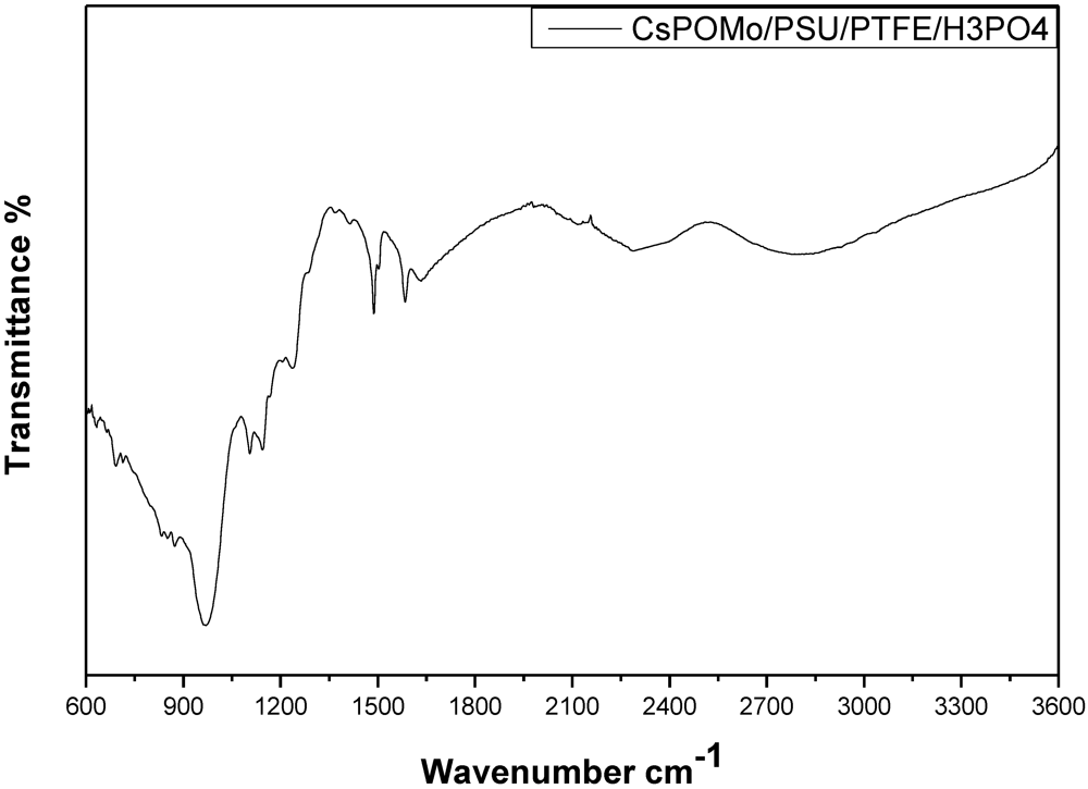
Figure 3 shows the infrared spectra of CsPOMo-PSU-PTFE-H
3PO
4. The characteristic vibration bands of P=O (1,065 cm
−1), of CsPOMo are apparent [
7]. The small peaks at 2,924 cm
−1, 1,620 cm
−1 and the sharp peak at 1,490 cm
−1 were attributed to quaternary ammonium group stretching vibration [
10]. For the PA/QDPSU membrane, a significant vibration peak was found at 960 cm
−1 and was attributed by the P=O vibration. The data suggest the successful preparation of CsPOMo-PSU-PTFE-H
3PO
4 membranes.
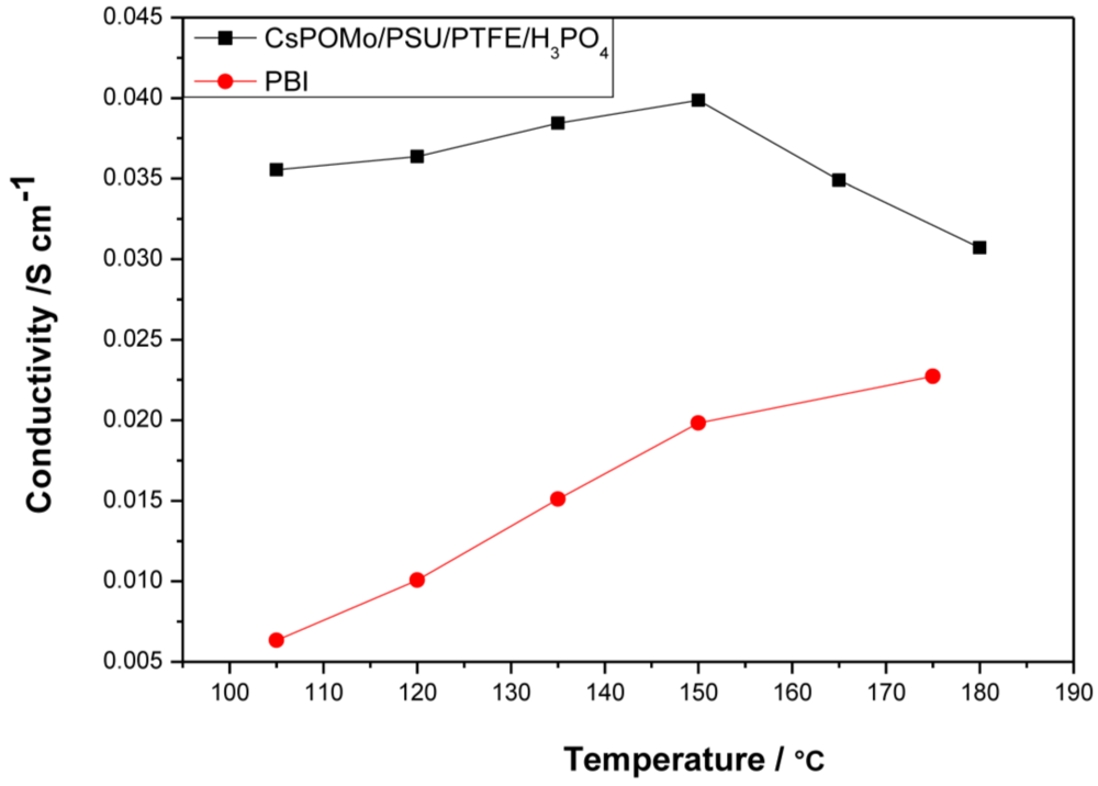
Figure 4 shows conductivity data of the CsHPA/PSU/PTFE membrane loaded with phosphoric acid (PRU 1.8) at a relative humidity <1%. The lower PA loading was chosen because excess phosphoric acid may result in a reduction of mechanical strength and elution problems of electrolytes [
10]. In general the PA inside the polymer membranes would be of two types “free acid” and “bonded acid”. The amount of “bonded acid” corresponds to 2.0 molecules of PA per repeat unit of QDPSU with the nitrogen sites for hydrogen bonding. Thus PA would more likely be retained inside the membrane and less easily removed during fuel cell applications.
Figure 3.
Infrared spectra of CsPOMo-PSU-PTFE-H3PO4 composite membrane.
Figure 3.
Infrared spectra of CsPOMo-PSU-PTFE-H3PO4 composite membrane.
Figure 4.
Conductivities of CsPOMo/PSU/PTFE composite membrane and polybenzimidazole (PBI) membrane loaded with H3PO4 (PRU 1.8) under relative humidity <1%. The thickness of both membranes is 30μm.
Figure 4.
Conductivities of CsPOMo/PSU/PTFE composite membrane and polybenzimidazole (PBI) membrane loaded with H3PO4 (PRU 1.8) under relative humidity <1%. The thickness of both membranes is 30μm.
Compared to the PBI membrane (0.02 S cm
−1 at 150 °C) with the same PA loading, the composite membrane had a much higher conductivity. The conductivity of composite membrane varied from 0.035 to 0.04 S cm
−1 in the temperature range of 105 to 150 °C. The highest conductivity of the PBI membrane was only 0.023 at 180 °C. The CsPOMo enhanced the conductivity of the membrane which may be due to a combination of the CsPOMo powder and the PSU/PTFE [
7]. The combination of the hydrophobic PTFE substrate and hydrophilic (QDPSU) structure could improve water retention inside the membrane which can benefit conductivity [
15]. The conductivities decreased when the temperature exceeded 150 °C, which was caused by dehydration of PA to form polyphosphate. However, this membrane could be considered for use at 150 °C.
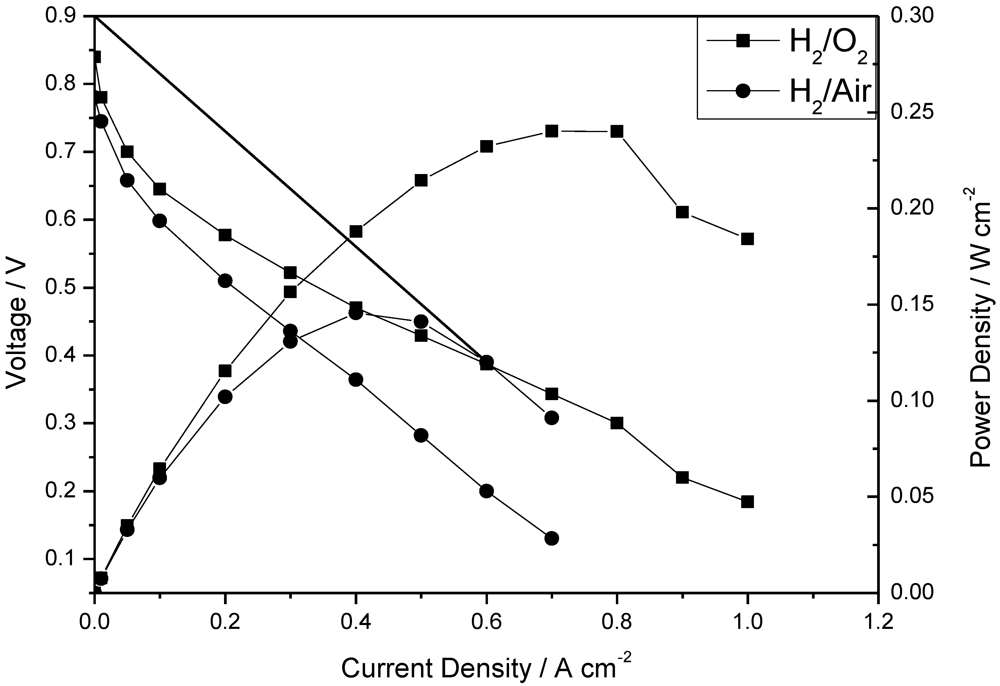
The polarization and power density curves of the H
2/O
2 fuel cell obtained at 150 °C at low humidity (<1%) with the CsPOMo/PSU/PTFE membrane are shown in
Figure 5. The total Pt catalyst loading was relatively low at 0.6 mg cm
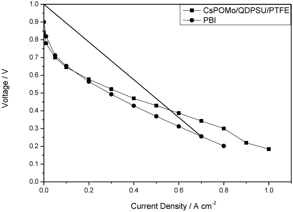
−2. The cell open circuit voltage was 0.85 V, which indicates that the relatively thin membrane (28 μm) was partially gas permeable, which probably resulted in some gas crossover and thus electrode polarization caused by mixed potentials at the electrodes. However, the thin membrane provided a reasonably good conductivity. A peak power density of 240 mW cm
−2 was achieved with oxygen. This peak power was only slightly better than that with a low acid loading PBI membrane (220 mW cm
−2, doping level 1.9) used in our previous work as shown in
Figure 6 [
11]. The performance achieved by the composite membrane could be attributed to its greater proton conductivity and superior water retention properties on the membrane surface at low acid loading [
7,
11].
Figure 5.
Polarization and power density curves of a fuel cell operated at 150 °C with (a) H2/O2; and (b) H2/air atmospheric pressure. Pt loading: cathode 0.4 mg cm−2; anode 0.2 mg cm−2; no gas humidity, H3PO4 PRU: 1.8, membrane thickness 28 μm. Gas rate: anode: 40 dm3 min−1; cathode: 70 dm3 min−1.
Figure 5.
Polarization and power density curves of a fuel cell operated at 150 °C with (a) H2/O2; and (b) H2/air atmospheric pressure. Pt loading: cathode 0.4 mg cm−2; anode 0.2 mg cm−2; no gas humidity, H3PO4 PRU: 1.8, membrane thickness 28 μm. Gas rate: anode: 40 dm3 min−1; cathode: 70 dm3 min−1.
Figure 6.
Polarization curves of CsPOMo/QDPSU/PTFE and PBI fuel cell operated at 150 °C with H2/O2. Atmospheric pressure, no gas humidity.
Figure 6.
Polarization curves of CsPOMo/QDPSU/PTFE and PBI fuel cell operated at 150 °C with H2/O2. Atmospheric pressure, no gas humidity.
The fuel cell with hydrogen and CO2 free air gave a peak power density of 140 mW cm−2 which was lower than that with oxygen, as would be expected from the lower partial pressure of oxygen with the former.
The internal resistance, as estimated from the voltage drop in the intermediate voltage range, gave a cell conductivity of around 0.006 S cm
−1. This conductivity was much less than that of the membrane itself and indicates significant voltage loss in the electrode layers (and other cell components). Furthermore, as
Figure 5 shows, there was an approximate 200 mV voltage loss from current densities of 0 to 0.1 A cm
−2 indicating that the catalyst compositions in the MEA were not “optimal” for the fuel cell. As no PA electrolyte was added to the catalyst layers and in theory no mobile PA would be present from the membrane, due to the low PA loading used, the electrode layer would have a relatively low ionic conductivity and thus catalyst utilization in the electrode reactions would be relatively low. Essentially only the Pt catalyst next to the membrane would be active, consequently explaining the high electrode activation losses.
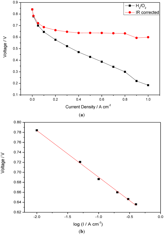
Figure 7 shows IR corrected polarization curves of the fuel cells operated with H
2/O
2 at 150 °C. IR correction is based on the combined resistance of membrane and electrode, measured from the slope of the cell voltage
vs. current density at the high current density region (0.4–0.8 A cm
−2). In this region the voltage loss associated with electrode polarization is small compared to that of the internal resistance. From the plot of the IR corrected voltage
vs. log (current density I), the slope (Tafel type) of the line is approximately 98 mV per decade. The value is close to the literature reported values (100 mV dec
−1) on ORR electrodes for phosphoric acid loaded PBI fuel cells [
16].
Figure 7.
(a) IR corrected polarization curves of CsPOMo/PSU/PTFE; (b) Tafel plots obtained from polarization curves (I is current density).
Figure 7.
(a) IR corrected polarization curves of CsPOMo/PSU/PTFE; (b) Tafel plots obtained from polarization curves (I is current density).
Overall, although the CsPOMo/PSU/PTFE composite is a potential membrane for polymer electrolyte membrane fuel cells, more studies are required to investigate the electrode catalyst layer composition and to establish suitable MEA preparation. Ideally this should incorporate the membrane material in the catalyst layers, and is the subject of on-going research.

