Dual-View Integral Imaging 3D Display Based on Multiplexed Lens-Array Holographic Optical Element

1
School of Instrumentation and Optoelectronic Engineering, Beihang University, Beijing 100191, China
2
School of Electronics and Information Engineering, Sichuan University, Chengdu 610065, China
*
Authors to whom correspondence should be addressed.
Appl. Sci. 2019, 9(18), 3852; https://doi.org/10.3390/app9183852
Submission received: 16 August 2019
/
Revised: 10 September 2019
/
Accepted: 11 September 2019
/
Published: 13 September 2019
(This article belongs to the Special Issue Holography, 3D Imaging and 3D Display)
Abstract
:Featured Application
In this paper, the dual-view integral imaging 3D display can be used in head-up display, augmented reality and so on.
Abstract
We propose a dual-view integral imaging 3D display based on a multiplexed lens-array holographic optical element (MHOE). A MHOE is a volume holographic optical element obtained by multiplexing technology, which can be used for dual-view integral imaging 3D display due to the angle selectivity of the volume HOE. In the fabrication of the MHOE, two spherical wavefront arrays with different incident angles are recorded using photopolymer material. In the reconstruction, two projectors are used to project the elemental image arrays (EIA) with corresponding angles for two viewing zones. We have developed a prototype of the dual-view integral imaging display. The experimental results demonstrate the correctness of the theory.
1. Introduction
Dual-view display provides different images for viewers in different directions. It can meet the needs of different viewers at the same time, and it saves a lot of space and cost. It is increasingly commercialized, especially for car navigation, home entertainment and business applications. For example, when a dual-view display is used in an automobile, it can represent navigation information for the driver and entertainment information for the passenger simultaneously. Some dual-view liquid crystal displays have been proposed [1,2], but they can only display 2D images. For automobile applications, optical see-through capacity is needed because the driver needs to see the road while watching the navigation information.
Recently, 3D displays, including holography display [3,4,5], integral imaging display [6,7,8,9], volumetric display [10,11] and so on, have received extensive attention. Integral imaging is considered to be one of the most promising display technologies. It has the advantages of full parallax [12] and continuous viewpoint [13], and it supplies various physiological depth cues, so viewers can freely change the accommodation and convergence without feeling any visual discomfort [14,15]. Integral imaging has a small viewing angle, and the viewing zone is periodically repeated. Therefore, it is suitable for dual-view or multi-view displays. By using some kinds of multiplexing methods, it can present different 3D images in different directions, and meet the needs of different viewers. In recent years, our team proposed several ways to implement dual-view 3D displays [16,17,18]. We proposed a dual-view integral imaging 3D display [16], but the viewing angle is only half of the conventional one. In order to increase the viewing angle of the dual-view 3D display, we proposed a dual-view integral imaging 3D display using polarizer parallax barriers [17], but the resolution of each 3D image is reduced to half of the conventional one. In order to solve these issues, Seoul University proposed a projection-type dual-view 3D display based on integral imaging [19], but the display system is bulky. Then we proposed a dual-view integral imaging 3D display using an orthogonal polarizer array and polarization switcher [18], but the brightness is not high.
In this paper, we propose a dual-view integral imaging 3D display system based on a MHOE. The viewing angle and resolution of 3D images in the dual viewing zones are almost same as the conventional one. The dual-view 3D display system can provide different 3D images in different zones via controlling the projection beams. In Section 2, the fabrication and reconstruction principles of the MHOE are analyzed, and the projection part of the dual-view 3D display system is designed. In Section 3, the different 3D images are displayed in different viewing zones, and the imaging characteristics of the MHOE are analyzed. The principle of the proposed system is verified by the display experiments.
2. Structure and Principle
The schematic diagram of the dual-view integral imaging 3D display system by using MHOE is shown in Figure 1, which consists of an MHOE, projector I and II. The MHOE is used as a projection screen, which records the wavefronts of a micro-lens array from two different directions by using two-step fabrication methods. Projection beams I are projected by projector I, which contain elemental image array (EIA) I, and projection beams I are projected on the MHOE with a pair of angles θ2 and θ3, which satisfies the Bragg condition. Then, 3D images I are reconstructed in the left viewing zone. Projection beams II with EIA II are projected by projector II, and projection beams II are incident onto the MHOE with a pair of angles θ5 and θ6. Then the Bragg condition is satisfied and 3D images II are reconstructed in the right viewing zone. Finally, two different 3D images are reconstructed in the dual viewing zones, respectively.
2.1. Fabrication and Reconstruction Principles of the MHOE
Compared with the conventional holographic optical element (HOE), the MHOE is recorded on the volume hologram, which has the characteristics of angular and spatial multiplexing. HOE has angular selectivity; when the incident beam deviates from the Bragg condition, the diffraction efficiency of the reconstructed beam is reduced. When the incident beam greatly deviates from Bragg condition, the diffracted beam cannot be reconstructed. Therefore, multiple optical elements can be recorded on a single holographic plate by angular and spatial multiplexing.
The angular and spatial multiplexing method are used in the fabrication process. Two sets of micro-lens array wavefronts are recorded in a single green sensitive photopolymer material with two different angles. The fabrication process is divided into two steps, which are shown in Figure 2. In the first step, the parallel beam I is incident into the micro-lens array at an oblique angle θ1, and then the spherical wavefront array I is generated. The reference beam I is generated by point source I. Reference beam I interferes with spherical wavefront array I with a pair of angles θ2 and θ3, as shown in Figure 2a. In the second step, the parallel beam II is incident into the micro-lens array at an oblique angle θ4, and then the spherical wavefront array II is generated. The reference beam II is generated by point source II, and reference beam II interferes with spherical wave array II with a pair of angles θ5 and θ6, as show in Figure 2b. The parallel beams I and II are symmetric to each other. By strictly controlling the exposure time of the first and second steps in the fabrication process. Finally, the required MHOE is obtained.
The reconstruction principle of the MHOE is shown in Figure 3. Reference beam I is projected onto the MHOE with a pair of angles θ2 and θ3. The incident angles of the reference beam I are consistent with the angles of fabrication, and the Bragg condition is satisfied. So the spherical wavefront array I can be reconstructed. Reference beam II is also projected onto the MHOE with a pair of angles θ5 and θ6. The incident angles of the reference beam II are the same as the angles of fabrication, and the Bragg condition is also satisfied. Then, the spherical wavefront II is reconstructed. Therefore, the MHOE has the optical characteristics of two sets of micro-lens arrays in different directions. Reference beams I and II are generated by the point source I and II, which have various directional light components. In the reconstruction of 3D images, a Bragg-mismatch occurs when reference beams are produced by projector I and II. So, the angular variation caused by angular deviation of the reconstructed beam should be analyzed.
2.2. MHOE as Imaging Optical Element in the Dual-View 3D Display
In the fabrication process, reference beams interfere with the spherical wavefront arrays. The spherical wavefront array consists of many small spherical waves, and the interference fringes are recorded on the holographic material. Each elemental lens in the MHOE is generated by the interference of a large spherical wave (reference beam) and a small spherical wave. The grating vectors of different positions on the MHOE are different. The reference beam is considered as a series of plane beams [20], whose wave vectors (Kr1~rn) are shown in Figure 4a. The spherical wavefront array can be regarded as a series of small spherical waves, which is shown in Figure 2. Each small spherical wave in the spherical wavefront array can also be considered as a series of plane beams, whose wave vectors (Ks1~sn) are shown in Figure 4a. So the change of the reconstructed beam of the MHOE could be explained by the wave vector relationship of the plane beams.
The recorded schematic diagram of the small spherical wave in the MHOE is shown in Figure 4b; the recorded grating vectors Kg can be expressed as [20]:
where Ks and Kr are the vectors of the small spherical wave in the spherical wavefront array and reference beam, respectively. In the reconstruction process, the projection beam project onto the MHOE with the vector Kp. The angle of the reconstructed beam can be expressed as [20]:
When the projection angle θp of the projection beam, the incident angle θr of the reference beam and the incident angle θs of the small spherical wave incident into the MHOE are determined, the angle θc of the reconstructed beam changes almost linearly, within the range of the projection angle of the projection beam. Therefore, the MHOE is suitable to be used as the imaging optical element in the dual-view 3D display.
2.3. Design of Projection Part for the Dual-View 3D Display
The projection part for the MHOE has to satisfy the Bragg conditions. Projection beam I must satisfy the projection angles θ2 and θ3 for reconstructed 3D images I in the left viewing zone, and projection beam II also must satisfy the projection angles θ5 and θ6 for reconstructed 3D image II in the right viewing zone. In this section, the projection part is realized based on two projectors, so that 3D image I and II are displayed simultaneously, as depicted in Figure 1.
The principle and design of the projection part for the dual-view 3D display are shown in Figure 5. When reference beam I is projected onto the MHOE with a pair of angles θ2 and θ3, spherical wavefront array I is reconstructed with the angle θ1. When reference beam II is projected onto the MHOE with a pair of angles θ5 and θ6, spherical wavefront array II is reconstructed with the angle θ4. The best view distance of the dual-view 3D display system is L, the focal length of the MHOE is f and the pitch is p. According to the geometric optics, the viewing angle of the left viewing zone can be expressed as:
and the viewing angle of the right viewing zone can be expressed as:
The projection part is designed to make sure that the left and right view zone are completely separated, and reconstructed 3D images I and II cannot cause crosstalk, which is shown in Figure 5.
3. Experiments and Results
3.1. Fabrication of the MHOE
In the first step, the experimental setup is shown in Figure 6a. The laser’s wavelength and power are 532 nm, and 400 mW, respectively. The thickness, resolution, sensitivity and average refractive index of the photopolymer material are 15 um, 12,000 line/mm, 10 mJ/cm2 and 1.47, respectively. The size of the micro-lens array used to fabricate the MHOE is 150 mm × 150 mm, in which the pith of each lens element is 1 mm and the focal length is about 3.3 mm. The laser beam is divided into two beams by a beam splitter (BS). One of the laser beams is expanded by a spatial filter (SF) and a collimating lens (CL), then the laser beam incident into the micro-lens array with the angle θ1 = 50° forms spherical wavefront array I. Another laser beam is reflected by mirror 1 (M1) and mirror 2 (M2), and then passes through the divergent lens (DL) to form spherical wave I. The angles of spherical wave I incident into the holographic plate is controlled to be θ2 = 61°, and θ3 = 81°. The interference occurs between the spherical waves I and spherical wavefront array I, and the interference fringes are recorded on the holographic plate.
In the second step, the experimental setup is shown in Figure 6b. The laser beam is divided into two beams by a BS. One of the laser beams is expanded by a SF and a CL, then the laser beam incident into the micro-lens array with the angle θ4 = 50° forms spherical wave array II. Another laser beam passes through the DL to form spherical wave II. The angle of spherical wave II incident into the holographic material is controlled to be θ5 = 61°, and θ6 = 81°. The interference occurs between the spherical waves I and spherical wavefront array I, and the interference fringes are recorded on the holographic plate. The holographic plate is post-processed to obtain the required MHOE. The size of the MHOE is 80 mm × 80 mm, and the diffraction efficiency and transmittance of the MHOE are greater than 85% and 80%, respectively. The exposure time is controlled by the electronic shutters. The detailed parameters of the optical devices are shown in Table 1.
In this paper, the MHOE is used as a projection screen, when the incident projection beam deviates greatly from the Bragg condition, the diffracted beam cannot be reconstructed and the 3D images also cannot be reconstructed. Therefore, the angular selectivity of the MHOE needs to be measured. The maximum deviated angle of the projection beam must be measured but the diffracted beam and 3D images cannot be reconstructed. The diffraction efficiency of the MHOE can be measured by the intensity of the transmitted and diffracted beam. The measurement formula of the diffraction efficiency can be expressed as [21]:
where ID and IT represent the intensity of the diffracted and transmitted beam, respectively. During the measurement, the incident angle of the reference beam is controlled by a rotation table, and the intensity of the diffracted beam of the MHOE is obtained by an optical power meter. The diffraction efficiency of the left and right view zones of the MHOE is measured, as shown in Figure 7. Through observation, when the incident angle of the reference beam is at 13°, the diffraction efficiency of the MHOE is less than 5%. When the incident angle of the reference beam is between −4.5° and 4.5°, the diffraction efficiency of the MHOE is higher than 50%. As shown in Figure 7, the maximum deviated angle of the MHOE is between −5° and 5° in the left and right viewing zones.
The angle between the incident angle θ3 of projector I and the incident angle θ5 of projector II is much larger than the maximum deviated angle of the MHOE, that is 38° > 10°. The angle between the incident angle θ2 of projector I and the incident angle θ6 of projector II is much larger than the maximum deviated angle of the MHOE, that is 38° > 10°. Therefore, there is no crosstalk between the left and right viewing zones.
The projector (BenQ MX518F) is used to ensure the diffraction efficiencies of the MHOE. The horizontal scanning frequency is 102 KHz, and the vertical scanning frequency is 120 Hz. The resolution of the projector is 1600 × 1200. The detailed parameters of the projector are shown in Table 1. Projection beam I is projected onto the MHOE with a pair of angles θ2 = 61° and θ3 = 81°, which are the same as in the first step. Then, spherical wavefront array I is reconstructed in the left direction, as shown in Figure 8a. Projection beam II is projected onto the MHOE with a pair of angles θ5 = 81° and θ6 = 61°, which are the same as in the second step. Then, spherical wavefront array II is reconstructed in the right direction, as shown in Figure 8b.
3.2. Experiments for Displaying Images on the Proposed Dual-View 3D Display
The projector is used in the experiment for displaying images. According to the incident angle requirement of the MHOE, projector I is placed on the left, and projection beam I is incident into the MHOE with a pair of angles θ2 = 61° and θ3 = 81°. Projector II is placed on the right, and projection beam II is incident onto the MHOE with a pair of angles θ5 = 81° and θ6 = 61°. Therefore, projection beams I and II are symmetrical to each other.
Figure 9 shows the experiment setup for the dual-view 3D display. In order to satisfy the incident angle about the MHOE, the two projectors are placed vertically, and the projection lens is positioned inside. The distance between the projection lenses of the projectors and the MHOE is 31 cm. Projectors I and II are 20 cm apart from each other in the horizontal direction. The projection lenses of projectors I and II are both 21 cm away from the optical table. The height of the MHOE is 19.5 cm from the optical table. The distance between the MHOE and the car model is 3 cm. The projectors are used to project the EIAs onto the MHOE. The projection beams of the projectors that meet the Bragg-match are directly projected onto the MHOE. The MHOE is used as a screen of the dual-view 3D display. Projector I projects EIA I as projection beam I, with a pair of angles θ2 = 61° and θ3 = 81° onto the MHOE. Then, 3D image I is reconstructed in the left viewing zone. Projector II projects EIA II as projection beam II, with a pair of angles θ5 = 61° and θ6 = 81° onto the MHOE. Then, 3D image II is reconstructed in the right viewing zone. In this paper, the pith of the elemental lens in the micro-lens array is 1 mm and the focal length is 3.3 mm. According to Equations (3) and (4), the viewing angles of the left and right viewing zone are Ω1 = 10.2° and Ω2 = 10.2°, respectively. According to the parameters of the micro-lens array, the viewing angle of the conventional integral imaging is about 12°. Therefore, the viewing angles in the dual viewing zones are almost the same as the conventional one.
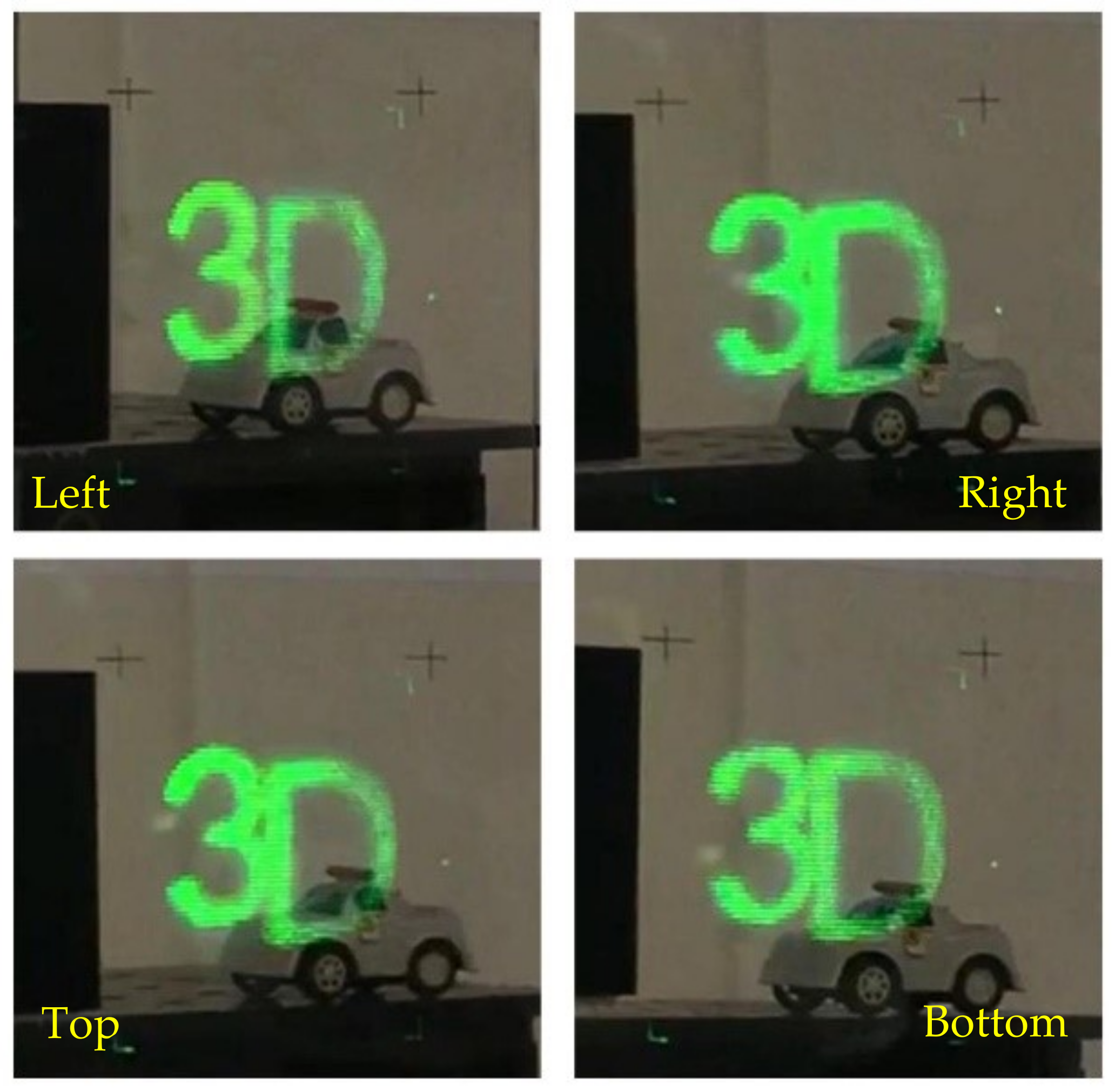
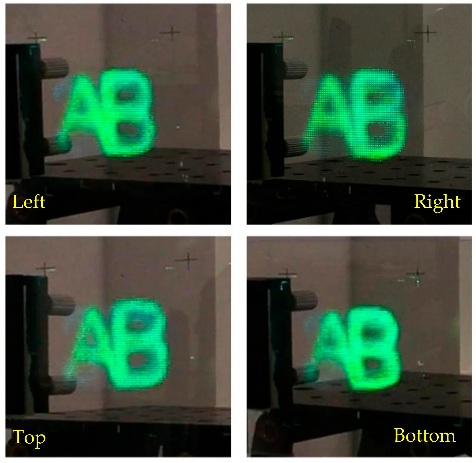
EIAs I and II are shown in Figure 10a,b, respectively. Each EIA consists of 70 × 70 image elements. EIA I is generated by a computer and consists of the characters “3” and “D”, in which “3” is located at −15 mm, and “D” is located at +15 mm. EIA II is also generated by a computer and consists of the characters “A” and “B”, in which “A” is located at −15 mm, and “B” is located at +15 mm.
3D image I reconstructed in the left view zone taken from the left, right, top and bottom directions are shown in Figure 11. We can see the horizontal parallax of the “3D” images from the left and right directions, and the vertical parallax of the “3D” images from the top and bottom directions. Reconstructed 3D image I has obvious horizontal and vertical parallaxes. Visualizations 1 and 2 clearly show the horizontal and vertical parallaxes between the “3”, “D” and the real object. The resolution of reconstructed 3D image I is almost the same as the conventional integral imaging 3D display, and 3D image I in the left view zone has high brightness and definition. The resolution of 3D image I is the same as the number of the image element 70 × 70 in EIA I.
Figure 12 shows 3D image II reconstructed in the right view zone taken from the left, right, top and bottom directions. We can see the horizontal parallax of the “AB” images from the left and right directions, and the vertical parallax of the “AB” images from the top and bottom directions. The reconstructed 3D image II has obvious horizontal and vertical parallaxes. Visualizations 2 and 3 clearly show the horizontal and vertical parallaxes between the “A”, “B” and the real object. The resolution of reconstructed 3D image II is also almost the same as the conventional integral imaging 3D display. The resolution of 3D image II is also the same as the number of the image element 70 × 70 in EIA II. The 3D images I and II have the same resolution, according to the parameters of the micro-lens array, the resolution of the conventional integral imaging is 70 × 70. Therefore, the resolution in the dual viewing zones are the same as the conventional one.
It was observed that there is slight image crosstalk in the 3D image reconstructed in the left and right viewing zone. When projection beam I is projected onto the MHOE, the light produces diffuse reflection on the glass substrate of the MHOE, and the diffuse light can produce slight crosstalk with reconstructed 3D image II in the right viewing zone. Reconstructed 3D image I in the left viewing zone has slight crosstalk, which is caused by the same reason as in the right viewing zone.
4. Conclusions
In this paper, we propose a dual-view 3D display. Two projectors are used to present different 3D images on the MHOE. Viewers can see the two different 3D images in the left and right viewing zones. The viewing angle and resolution of the reconstructed 3D images in the two viewing zones are almost the same as the conventional integral imaging 3D display. In addition, the fusion of 3D images with real objects is realized. It can be used for the car head up display and medical devices.
Supplementary Materials
The following are available online at https://www.mdpi.com/2076-3417/9/18/3852/s1.
Author Contributions
Conceptualization, Q.W. and D.L.; methodology, H.Z.; software, H.Z.; validation, Q.W., H.D.; formal analysis, H.Z.; investigation, M.H.; writing—original draft preparation, H.Z.; writing—review and editing, H.Z., Q.W., D.H., M.H., D.L.; visualization, H.Z.; funding acquisition, Q.W.
Funding
This work is supported by the National Key R&D Program of China (2017YFB1002900) and National Natural Science Foundation of China (61535007 and 61775151).
Conflicts of Interest
The authors declare no conflict of interest.
References
- Cui, J.P.; Li, Y.; Yan, J.; Cheng, H.C.; Wang, Q.H. Time-multiplexed dual-view display using a blue phase liquid crystal. J. Disp. Technol. 2013, 9, 87–90. [Google Scholar] [CrossRef]
- Hsieh, C.T.; Shu, J.N.; Chen, H.T.; Huang, C.Y.; Tian, C.J.; Lin, C.H. Dual-view liquid crystal display fabricated by patterned electrodes. Opt. Express 2012, 20, 8641–8648. [Google Scholar] [CrossRef] [PubMed]
- Zhao, Y.; Cao, L.; Zhang, H.; Kong, D.; Jin, G. Accurate calculation of computer-generated holograms using angular-spectrum layer-oriented method. Opt. Express 2015, 23, 25440–25449. [Google Scholar] [CrossRef] [PubMed]
- Zhang, H.; Zhao, Y.; Cao, L.; Jin, G. Fully computed holographic stereogram based algorithm for computer-generated holograms with accurate depth cues. Opt. Express 2015, 23, 3901–3913. [Google Scholar] [CrossRef] [PubMed]
- Gao, Q.; Liu, J.; Han, J.; Li, X. Monocular 3D see-through head-mounted display via complex amplitude modulation. Opt. Express 2016, 24, 17372–17383. [Google Scholar] [CrossRef] [PubMed]
- Sang, X.; Fan, F.C.; Jiang, C.C.; Choi, S.; Dou, W.; Yu, C. Demonstration of a large-size real-time full-color three-dimensional display. Opt. Lett. 2009, 34, 3803–3805. [Google Scholar] [CrossRef] [PubMed]
- Yu, C.; Yuan, J.; Fan, F.C.; Jiang, C.C.; Choi, S.; Sang, X. The modulation function and realizing method of holographic functional screen. Opt. Express 2010, 18, 27820–27826. [Google Scholar] [CrossRef] [PubMed]
- Lee, H.H.; Huang, P.J.; Wu, J.Y.; Hsieh, P.Y.; Huang, Y.P. A 2D/3D hybrid integral imaging display by using fast switchable hexagonal liquid crystal lens array. In Proceedings of the Three-dimensional Imaging, Visualization, & Display. International Society for Optics and Photonics, Anaheim, CA, USA, 10 May 2017; Volume 10219, pp. 1021910–1021916. [Google Scholar]
- Oi, R.; Chou, P.Y.; Jackin, B.J.; Wakunami, K.; Ichihashi, Y.; Okui, M.; Huang, Y.P.; Yamamoto, K. Three-dimensional reflection screens fabricated by holographic wavefront printer. Opt. Eng. 2018, 57, 61605–61612. [Google Scholar]
- Patel, S.K.; Cao, J.; Lippert, A.R. A volumetric three-dimensional digital light photoactivatable dye display. Nat. Commun. 2017, 8, 15239–15246. [Google Scholar] [CrossRef] [PubMed]
- Kota, K.; Satoshi, H.; Yoshio, H. Volumetric bubble display. Optica 2017, 4, 298–302. [Google Scholar]
- Wang, X.; Hua, H. Theoretical analysis for integral imaging performance based on microscanning of a microlens array. Opt. Lett. 2008, 33, 449–451. [Google Scholar] [CrossRef] [PubMed]
- Javidi, B.; Hua, H. A 3d integral imaging optical see-through head-mounted display. Opt. Express 2014, 22, 13484–13491. [Google Scholar]
- Zhang, H.L.; Deng, H.; Yu, W.T.; He, M.Y.; Li, D.H.; Wang, Q.H. Tabletop augmented reality 3D display system based on integral imaging. J. Opt. Soc. Am. B 2017, 34, 16. [Google Scholar] [CrossRef]
- He, M.Y.; Zhang, H.L.; Deng, H.; Li, X.W.; Wang, Q.H. Dual-view-zone tabletop 3D display system based on integral imaging. Appl. Opt. 2018, 57, 952–958. [Google Scholar] [CrossRef] [PubMed]
- Wu, F.; Deng, H.; Luo, C.G.; Li, D.H.; Wang, Q.H. Dual-view integral imaging three-dimensional display. Appl. Opt. 2013, 52, 4911–4914. [Google Scholar] [CrossRef] [PubMed]
- Wu, F.; Wang, Q.H.; Luo, C.G.; Li, D.H.; Deng, H. Dual-view integral imaging 3D display using polarizer parallax barriers. Appl. Opt. 2014, 53, 2037–2039. [Google Scholar] [CrossRef] [PubMed]
- Wang, Q.H.; Ji, C.C.; Li, L.; Deng, H. Dual-view integral imaging 3D display by using orthogonal polarizer array and polarization switcher. Opt. Express 2016, 24, 9–16. [Google Scholar] [CrossRef] [PubMed]
- Jeong, J.; Lee, C.K.; Hong, K.; Yeom, J.; Lee, B. Projection-type dual-view three-dimensional display system based on integral imaging. Appl. Opt. 2014, 53, 12–18. [Google Scholar] [CrossRef] [PubMed]
- Li, G.; Lee, D.; Jeong, Y.; Lee, B. Fourier holographic display for augmented reality using holographic optical element. Disp. Technol. Int. Soc. Opt. Photonics 2016, 9770, 97700D. [Google Scholar]
- Tao, S.Q.; Wang, D.Y.; Qing, J.Z.; Yuan, Q. Optical Hologram Storage; Beijing University of Technology Press: Beijing, China, 1998. [Google Scholar]
Figure 1.
Schematic diagram of the dual-view 3D display system by using the MHOE.

Figure 2.
Fabrication principle of the MHOE, (a) the first step and (b) the second step.

Figure 3.
Reconstruction principle of the MHOE.

Figure 4.
(a) Grating vector diagram of the elemental lens in the MHOE, and (b) wavefront recording schematic diagram of the elemental lens in the MHOE.
Figure 4.
(a) Grating vector diagram of the elemental lens in the MHOE, and (b) wavefront recording schematic diagram of the elemental lens in the MHOE.

Figure 5.
Principle and design of the projection part for the dual-view 3D display.

Figure 6.
Setup for fabrication of the MLAHOE, (a) the first step, and (b) the second step.

Figure 7.
Diffraction efficiency of the left and right viewing zone.

Figure 8.
Reconstruction of the wavefronts of the lens array (a) in the left viewing zone, and (b) in the right viewing zone.
Figure 8.
Reconstruction of the wavefronts of the lens array (a) in the left viewing zone, and (b) in the right viewing zone.

Figure 9.
Experiment setup for the dual-view 3D display.

Figure 10.
(a) EIA I and (b) EIA II.

Figure 11.
Experimental results in the left viewing zone (see Supplementary Materials visualization 1 and visualization 2), the parallax images in the left, right, top, and bottom four directions.
Figure 11.
Experimental results in the left viewing zone (see Supplementary Materials visualization 1 and visualization 2), the parallax images in the left, right, top, and bottom four directions.

Figure 12.
Experimental results in the right viewing zone (see Supplementary Materials visualization 2 and visualization 3), the parallax images in the left, right, top, and bottom four directions.
Figure 12.
Experimental results in the right viewing zone (see Supplementary Materials visualization 2 and visualization 3), the parallax images in the left, right, top, and bottom four directions.


Table 1.
Parameters of the optical devices in our experiments.
| Components | Parameters | Values |
|---|---|---|
| Green laser | Power | 400 mW |
| Wavelength | 532 nm | |
| Green sensitive photopolymer material | Thickness | 15 um |
| Resolution | 12000 line/mm | |
| Sensitivity | 10 mJ/cm2 | |
| Averaged refractive index | 1.47 | |
| Micro-lens array | Pitch | 1 mm |
| Focal length | 3.3 mm | |
| Beam splitter | Coupling ration | 1:1 |
| Projector | Model | MX518F |
| Resolution | 1600 × 1200 | |
| Horizontal scanning frequency | 102 KHz | |
| Vertical scanning frequency | 102 Hz |
© 2019 by the authors. Licensee MDPI, Basel, Switzerland. This article is an open access article distributed under the terms and conditions of the Creative Commons Attribution (CC BY) license (http://creativecommons.org/licenses/by/4.0/).
Share and Cite
MDPI and ACS Style
Zhang, H.; Deng, H.; He, M.; Li, D.; Wang, Q. Dual-View Integral Imaging 3D Display Based on Multiplexed Lens-Array Holographic Optical Element. Appl. Sci. 2019, 9, 3852. https://doi.org/10.3390/app9183852
AMA Style
Zhang H, Deng H, He M, Li D, Wang Q. Dual-View Integral Imaging 3D Display Based on Multiplexed Lens-Array Holographic Optical Element. Applied Sciences. 2019; 9(18):3852. https://doi.org/10.3390/app9183852
Chicago/Turabian StyleZhang, Hanle, Huan Deng, Minyang He, Dahai Li, and Qionghua Wang. 2019. "Dual-View Integral Imaging 3D Display Based on Multiplexed Lens-Array Holographic Optical Element" Applied Sciences 9, no. 18: 3852. https://doi.org/10.3390/app9183852
Note that from the first issue of 2016, this journal uses article numbers instead of page numbers. See further details here.