3D Display System Based on Spherical Wave Field Synthesis


1
Bremer Institut für angewandte Strahltechnik GmbH (BIAS), Klagenfurter Strasse 5, 28359 Bremen, Germany
2
Department of Photonics, College of Electrical and Computer Engineering, National Chiao Tung University, Hsinchu 30010, Taiwan
3
Faculty of Physics and Electrical Engineering, University of Bremen, 28359 Bremen, Germany
*
Author to whom correspondence should be addressed.
Appl. Sci. 2019, 9(18), 3862; https://doi.org/10.3390/app9183862
Submission received: 15 August 2019
/
Revised: 11 September 2019
/
Accepted: 12 September 2019
/
Published: 14 September 2019
(This article belongs to the Special Issue Holography, 3D Imaging and 3D Display)
Abstract
:We present a novel concept and first experimental results of a new type of 3D display, which is based on the synthesis of spherical waves. The setup comprises a lens array (LA) with apertures in the millimeter range and a liquid crystal display (LCD) panel. Each pixel of the LCD creates a spherical wave cutout that propagates towards the observer. During the displaying process, the curvature of the spherical waves is dynamically changed by either changing the distance between LA and LCD or by adapting the focal lengths of the lenses. Since the system, similar to holography, seeks to approximate the wavefront of a natural scene, it provides true depth information to the observer and therefore avoids any vergence–accommodation conflict (VAC).
1. Introduction
Recently, display technologies [1,2] have grown dramatically, and flat-panel displays based on LCDs or organic LEDs dominate the market. Especially in the last decade, three-dimensional (3D) display systems [3,4,5] have greatly advanced. Compared with a flat panel display, 3D technologies can not only provide images, but also deliver depth information to create a more immersive vision experience. According to whether the observer needs to wear 3D glasses or not, 3D displays can be classified as stereoscopic and autostereoscopic systems, which have different applications in human life. Traditional 3D displays are based on the principle of binocular parallax [6,7], in order to give the observer two different images for both eyes to merge as one 3D image. According to the human visual experiment [8,9], the accommodation of the eye lens is focused on the display plane, which is different from the vergence, which is directed towards the reconstructed object. This mismatch is called vergence–accommodation conflict (VAC). It induces dizziness and makes the observer feel uncomfortable. Therefore, floating image display systems, which can reconstruct images in space with real depth cues in order to solve the VAC issue, are one of the prime goals of 3D display technology. One way to implement a floating image display is to synthesize a wave field, so that it appears to be scattered by a natural scene or object. Currently, two different approaches are reported, which can be classified under this category: holographic displays and light field (LF) displays.
Holographic displays are often considered as the gold standard of 3D display systems. They can, in principle, create any arbitrary wave field and therefore provide the most comfortable experience to the observer. Because the shape of the wavefield can be fully controlled, a well-made hologram can appear indistinguishable from a real object. However, while holography works great for static scenes using holographic film material, up to now there exists no practical solution for dynamic displays. The reason for this is that holography relies on forming wavefields based on the physical principle of diffraction. This calls for a huge space bandwidth product (i.e., number of pixels on the order of ) which is required to generate the fine diffractive structures across the area of a macroscopic display screen [10,11,12].
On the other hand, the structure of LF display technologies [13,14,15,16,17,18,19,20] is simple. It just consists of a micro-lens array (MLA) and a display panel. The aim of an LF system is to approximate the light field of a natural scene. From a wave field perspective, the light field can be described by a set of plane waves. However, the number of plane waves in an LF system is limited by the number of display pixels, and the diameter of the plane waves typically equals the diameter of the involved micro-lenses, i.e., is comparably small. This leads to a strongly fragmented representation of the ideal wave field. As a consequence, light field systems usually have to find a trade-off between spatial and angular resolution and can only display very limited scenes. In addition, the depth range around the central depth plane (CDP) [21], which is the plane of the highest spatial resolution, is usually narrow.
In this publication, we present a new approach to a floating image display system, which is based on synthesizing spherical waves instead of plane waves in order to overcome these drawbacks. Similar to an LF system, the corresponding setup consists of a display panel and a lens array (LA). Yet, compared with the LF system, the aperture size of the individual lenses is much larger. Additionally, in order to control the curvature of the spherical waves, the distance between the display and the LA is dynamically changed. The benefit of this approach can be understood in the wave field picture, since using spherical waves instead of plane waves adds more degrees of freedom to the base functions of the synthesis. It, therefore, represents one step further towards true holography, which offers the highest degree of wavefront complexity. Yet, in contrast to holography, the method can be implemented with already existing technology. As an additional benefit, the LA is a refractive element with very little dispersion, so that the system operates almost wavelength-independently and can, therefore, display colored scenes.
2. Principle and Design of Wave Field Synthesis 3D Imaging System
2.1. Optical System Principle
In a real environment, the surface of an object can be assumed to be composed of a huge number of dipoles. Each of them is excited when illuminated and becomes the source of dipole radiation. Because the dipoles are unordered, the scattered light can be approximated as a set of mutually incoherent spherical waves, as shown in Figure 1. This simple gedankenexperiment shows that spherical waves can be very useful as a polynomial basis to imitate and synthesize wave fields generated by natural scenes.
We will employ this principle by using the display scheme depicted by Figure 2. It consists of a liquid crystal display (LCD) and an lens array (LA). The lateral pixel position is given by while the lateral position of the virtual object point is defined as . The wavefront behind the lens propagates in the direction determined by .
In the system, light originating from each LCD pixel will form a spherical wave. The curvature of the spherical waves, which also defines the distance to its origin, can be controlled by either changing the optical path between the LCD and the LA (the distance d) or, more conveniently, by changing the focal length of the lenses using a dynamic LA. The setup resembles an LF display. However, the basic principle is completely different. While an LF display seeks to generate rays (i.e., plane waves), we use a set of spherical waves to synthesize a wave field. Compared with rays, spherical waves exhibit the additional parameter of curvature. Therefore, the curvature has to be dynamically varied during the display process using one of the above-mentioned techniques. In our work, we change the curvature by mechanically varying the optical path between LCD and LA. Additionally, since the aim is to generate wide-field spherical waves rather than rays (narrow plane waves), the individual lenses of the LA exhibit a much larger aperture.
If one of the spherical waves hits the eye of the observer, the eye lens adjusts properly to image the origin of the spherical wave, thus creating the sensation of a point floating in space. Multiple points can then be used to create surfaces of objects or even complex scenes. Different depth layers can be addressed by changing the curvature, while lateral coordinates can be selected by the pixel position on the LCD panel. For the rendering, we use a ray trace approach and follow the line that intersects the center of a lens and the center of a corresponding LCD pixel. Whether the pixel is switched on or not depends on the virtual distance to the center of the spherical wave. If it is in close vicinity to an object’s surface and nothing is blocking the path (object occlusion), the pixel is switched on.
For the renderer, it is, therefore, necessary to calculate from the distance d between the LCD and the LA and the focal length f of the lenses. The separability of the problem allows us to treat it in 2 dimensions, x, and z. To further simplify the calculation, the parabolic approximation is used to describe the complex amplitude of light originating from a specific LCD pixel in front of its associated lens [22], which is given by
The origin is located at the corresponding lens center, indicates the pixel coordinate relative to the lens center, represents the amplitude provided by the pixel and is the wave number. In addition, the lens modulation based on the thin lens approximation can be described as
By multiplying Equation (1) and (2), the perceived wave function of the pixel after passing through the lens can be written as
where the first exponential term with square in x indicates the curvature, and the second term linear in x represents the average propagation direction of the corresponding spherical wave cutout, which forms behind the lens. By comparing Equation (1) and (3), the spherical wave can be assumed to originate from a point source in a distance behind the lens array, which depends on d and f according to
Please note that due to their limited aperture, the lenses only produce a cutout of a spherical wave rather than the entire wave field. This effect is an important requirement for the spherical wave field synthesis. It enables creating the effect of object occlusions, i.e., when one object in the front blocks parts of the spherical waves originating from an object behind it. At this point, the main direction in which the spherical wave cutout propagates shall be derived. According to Figure 2, one can find the geometrical relation
Within the paraxial approximation, this is equivalent to
Inserting Equation (6) turns the second exponential term in Equation (3) into a plane wave travelling along the direction with respect to the lens plane. The angle therefore defines the direction in which the spherical wave cutout propagates. The Equations (4) and (6) are crucial for the design of the desired wave field to depict an object in a virtual distance behind the lens’ plane. Finally, in our experiments, each LCD pixel was associated to the lens in front of it (in the direction of the optical axis). We avoided crosstalk between neighboring lenses by a 3D-printed parallax barrier.
2.2. Optical Components
A lens array (LA) (model Stock no.63-231 from Edmund Optics GmbH) is adapted as the refractive component of our system, whose specifications are shown in Table 1. The arrangement as well as the aperture of the lenses is rectangular and the substrate is made from B270 material with high transmittance in the range of visual wavelengths. The working area is 58 mm by 60 mm. Since the fundamental principle of our system is spherical wave field synthesis, a larger size, 5.4 mm by 7.0 mm, of the lenses compared with a MLA is selected to avoid strong fragmentation of the wavefronts due to small lens apertures. In addition, the focal length of the LA is 41.90 mm.
A commercial iPhone 7 plus with 401 ppi is chosen as the display device and its specifications are shown in Table 2. Hence the system is capable of working with partially coherent light, which is more convenient compared to the requirements of holographic displays. The two main factors of selecting the specific display are the high resolution and the wide color gamut, which affect imaging quality of the reconstructed images directly.
3. Experiments and Results
To verify the concept of a 3D display by means of spherical wave synthesis, a prototype was set up. Figure 3 illustrates the optical components and configuration of the proposed system, which just consists of an LA and an LCD panel. For the prototype setup, all-optical components are fixed on a stage with all six degrees of freedom to adjust the relative position between the LA and the LCD precisely. Moreover, a stepper motor is employed to adjust the distance d along the z-axis fast and accurately. The depicted images can be recorded with a camera, which is mounted vertically above the LA.
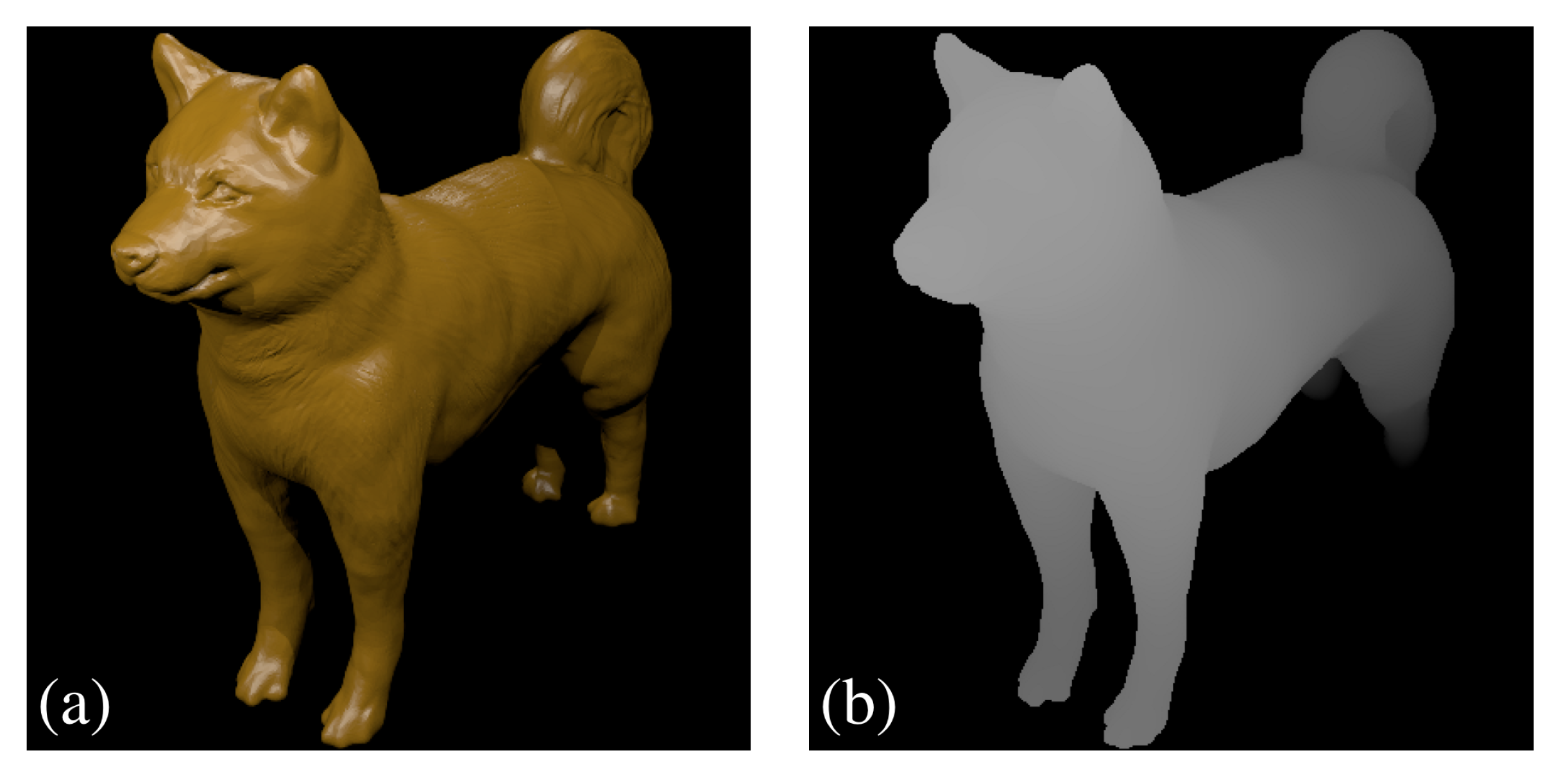
In preparation for the experiment, a color image and a depth image of a 3D model (dog) were rendered by using the stereo modeling software Blender, as seen from Figure 4. The depth range of the dog is set from 80 mm to 180 mm underneath the LA and the model was sliced into 11 depth planes. By using the ray-tracing based rendering approach described in Section 2.1, the patterns to be displayed by the LCD were generated for all depth planes, as shown in Figure 5. By following Equation (4), the distance d between LCD and LA was controlled during the display process using the stepper motor.
We used a CCD camera to imitate the eye of the observer. The system works in full color, yet we used a monochrome camera to better inspect fine details of the object representation. Interested readers can find the full-color Video S1 of the display in the Supplementary Material. To demonstrate focusing effects, the camera is equipped with a high numerical aperture objective with F# 0.95. The 3D display scheme is based on the effect of visual persistence [23], i.e., all recorded CCD images are added/integrated up while the distance d is scanned through all 11 depth planes.
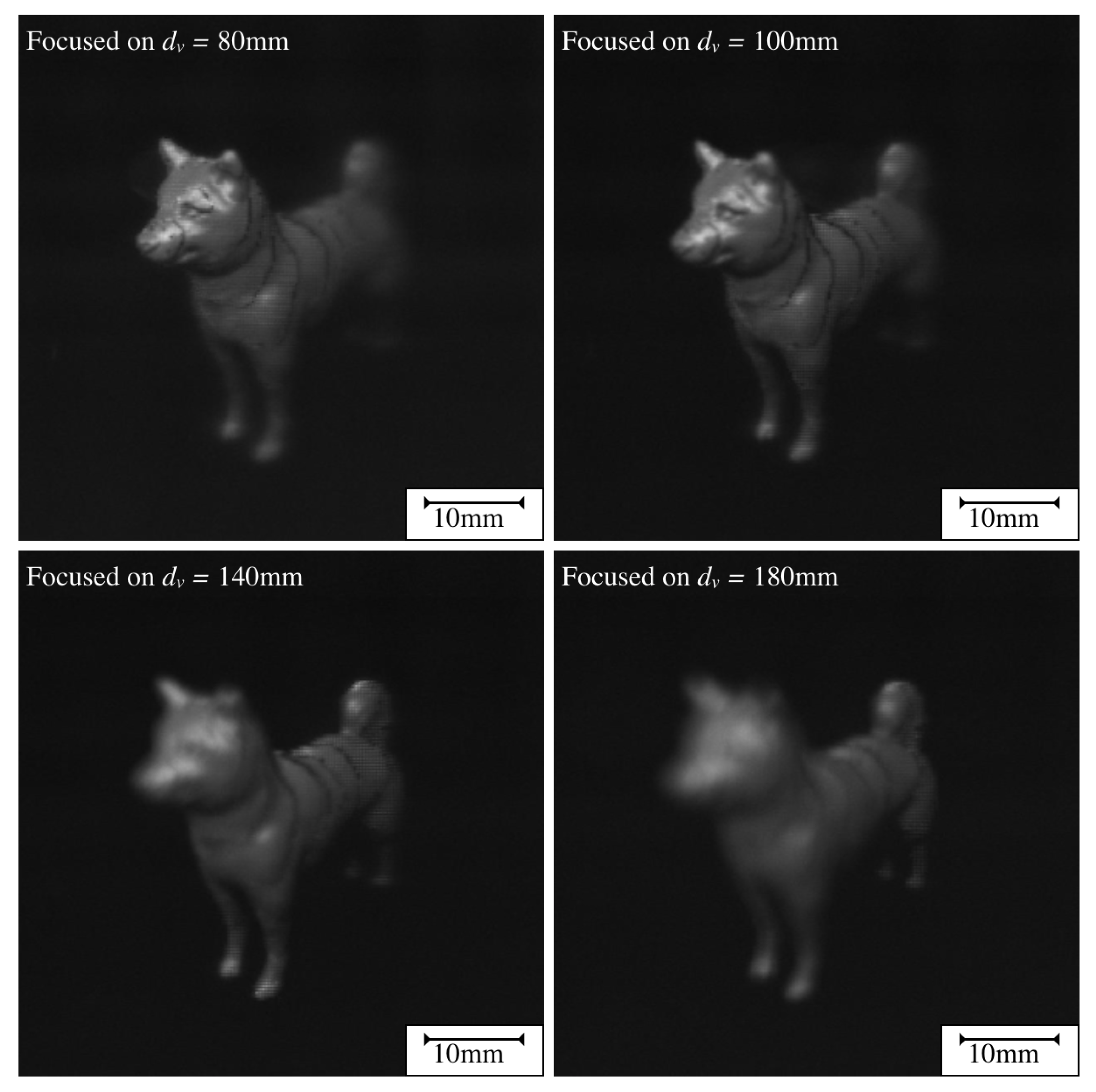
To show focus blur, we have recorded multiple images with the objective being focused on different parts of the displayed dog. The results are seen in Figure 6. In the results, it can be easily recognized that the tail of the dog is behind the head, as expected from the model. In addition, when the focusing plane of the objective is set at 80 mm, the dog’s head is much clearer than the tail, and the captured image at the unfocused areas exhibits a gradual blur from neck to tail, which indicates that the reconstructed image provides continuous depth information. When the focusing plane is subsequently moved from 80 mm to 180 mm, the focused area would be changed from head to neck, forefoot, body, tail, and hindfoot, where the blurred areas are also shifted correspondingly. This phenomenon strongly confirms that the reconstructed images in our system contain real depth information with focus cue, similar to what is expected from a hologram.
To demonstrate the effect of parallax, two letters in different depth planes are depicted, which is shown in Figure 7. A letter “A” at the virtual distance and a letter “B” at . For the used LA with a focal length of mm, this results in a vertical distance between the LCD and the LA of mm and mm, respectively. The alignment of the LCD and the LA is kept the same. The camera, placed in a vertical distance of 750 mm above the LA, was horizontally moved between capturing three images along the x-axis to change the viewing angle while the camera’s objective kept being focused on the depth plane of the “A”.
Figure 7a was captured while the camera was horizontally shifted by 40 mm from the optical axis in the positive x-direction (to the right), resulting in a change of the viewing angle by . In Figure 7b, the camera is placed on the optical axis. Figure 7c shows the case where the camera was moved by −40 mm in the other direction (to the left), which changed the viewing angle by . As expected, the letter closer to the viewer (“A”) seems to move horizontally relatively to the letter further in the background (“B”). If the camera is placed on the right side of the optical axis, the “A” appears to be laterally closer to the “B” and if the camera is placed on the left side, the “A” is laterally farther away from the “B”. This experiment clearly shows the inherent effect of parallax that the system is able to provide as a crucial depth cue. The Video S2 in the Supplementary Materials also shows parallax and focus blur of the display.
4. Conclusions
We have presented a new approach for the 3D display of natural scenes, which is based on the synthesis of spherical waves. From a wave field perspective, the method can be categorized between LF displays, which seek to recreate a scene by synthesizing plane waves (rays), and holography, which can generate arbitrary wave fields but is technically very challenging. In this sense, our method represents a significant step towards true, full color, dynamic holography, yet with the great benefit that it can be implemented with already existing technology. As a proof of concept, we have shown that a system based on the method recreates crucial depth cues, such as full parallax and depth blurring and by design avoids any vergence-accomodation conflict.
The main drawback of the current implementations of the method is the slow frame rate. Due to technical limitations of the moving stages, it requires several seconds to capture a single 3D frame. In the future, we will therefore concentrate on improving the response time of the stages or on rapidly varying the focal length of the lens array in order to achieve multiple frames per second, and thus creating an immersive experience for the observer.
Supplementary Materials
The following is available online at https://www.mdpi.com/2076-3417/9/18/3862/s1, Video S1: Experimental results showing the color performance of the display, Video S2: Experimental results showing the parallax and the focus blur of the display.
Author Contributions
Conceptualization, C.F.; formal analysis, C.F. and D.P.; investigation, P.-Y.C. and D.P.; methodology, C.F.; resources, R.B.B.; supervision, C.F. and R.B.B.; validation, P.-Y.C. and D.P.; visualization, P.-Y.C. and D.P.; writing—original draft, C.F., P.-Y.C. and D.P.; writing—review and editing, R.B.B.
Funding
This research was funded by the Deutsche Forschungsgemeinschaft (DFG) grant number 250959575, and Ministry of Science and Technology (MOST) in Taiwan grant number MOST 107-2221-E-009-115-MY3.
Acknowledgments
The authors would like to thank Reiner Klattenhoff for valuable help with the experiments. We are also grateful to the Deutsche Forschungsgemeinschaft (DFG) for funding this work under the grant 250959575 (RELPH-II).
Conflicts of Interest
The authors declare no conflict of interest.
Abbreviations
The following abbreviations are used in this manuscript:
| 3D | Three-dimensional |
| LA | Lens array |
| LCD | Liquid crystal display |
| VAC | Vergence–accommodation conflict |
| LF | Light field |
| MLA | Micro-lens array |
| CDP | Central depth plane |
| CCD | Charge coupled device |
References
- Hainich, R.R.; Bimber, O. Displays–Fundamentals & Applications, 2nd ed.; CRC Press: Boca Raton, FL, USA, 2017. [Google Scholar]
- Souk, J. (Ed.) Flat Panel Display Manufacturing; Wiley: Hoboken, NJ, USA, 2018. [Google Scholar]
- Geng, J. Three-dimensional display technologies. Adv. Opt. Photonics 2013, 5, 456–535. [Google Scholar] [CrossRef] [PubMed] [Green Version]
- Holliman, N. 3D Display Systems; Department of Computer Science: Durham, UK, 2005; pp. 456–535. [Google Scholar]
- Hill, L.; Jacobs, A. 3-D Liquid Crystal Displays and Their Applications. Proc. IEEE 2006, 94, 575–590. [Google Scholar] [CrossRef]
- Wheatstone, C. Contributions to the physiology of vision.–Part the first. On some remarkable, and hitherto unobserved, phenomena of binocular vision. Phil. Trans. R. Soc. 1838, 128, 371–394. [Google Scholar]
- Lappe, M.; Bremmer, F.; den Berg, A.V. Perception of self-motion from visual flow. Trends Cogn. Sci. 1999, 3, 329–336. [Google Scholar] [CrossRef]
- Kim, J.; Kane, D.; Banks, M.S. The rate of change of vergence-accommodation conflict affects visual discomfort. Vis. Res. 2014, 105, 159–165. [Google Scholar] [CrossRef] [PubMed]
- Burke, R.; Brickson, L. Focus cue enabled head-mounted display via microlens array. TOG 2013, 32, 220. [Google Scholar]
- Agour, M.; Falldorf, C.; Bergmann, R.B. Holographic display system for dynamic synthesis of 3D light fields with increased space bandwidth product. Opt. Express 2016, 24, 14393–14405. [Google Scholar] [CrossRef] [PubMed]
- Blanche, P.A.; Bablumian, A.; Voorakaranam, R.; Christenson, C.; Lin, W.; Gu, T.; Flores, D.; Wang, P.; Hsieh, W.Y.; Kathaperumal, M.; et al. Holographic three-dimensional telepresence using large-area photorefractive polymer. Nature 2010, 458, 80–83. [Google Scholar] [CrossRef] [PubMed]
- Häussler, R.; Gritsai, Y.; Zschau, E.; Missbach, R.; Sahm, H.; Stock, M.; Stolle, H. Large real-time holographic 3d displays: enabling components and results. Appl. Opt. 2017, 56, F45–F52. [Google Scholar] [CrossRef] [PubMed]
- Huang, F.C.; Luebke, D.P.; Wetzstein, G. The light field stereoscope. Acm Trans. Graph. 2015, 34, 60:1–60:12. [Google Scholar] [CrossRef]
- Chou, P.Y.; Wu, J.Y.; Huang, S.H.; Wang, C.P.; Qin, Z.; Huang, C.T.; Hsieh, P.Y.; Lee, H.H.; Lin, T.H.; Huang, Y.P. Hybrid light field head-mounted display using time-multiplexed liquid crystal lens array for resolution enhancement. Opt. Express 2019, 27, 1164–1178. [Google Scholar] [CrossRef] [PubMed]
- Jang, J.S.; Javidi, B. Three-dimensional integral imaging of micro-objects. Opt. Lett. 2004, 29, 1230–1232. [Google Scholar] [CrossRef] [PubMed] [Green Version]
- Levoy, M.; Zhang, Z.; McDowall, I. Recording and controlling the 4D light field in a microscope using microlens arrays. J. Microsc. 2009, 235, 144–162. [Google Scholar] [CrossRef] [PubMed] [Green Version]
- Huang, H.; Hua, H. Systematic characterization and optimization of 3D light field displays. Opt. Express 2017, 25, 18508–18525. [Google Scholar] [CrossRef] [PubMed] [Green Version]
- Lanman, D.; Luebke, D. Near-eye light field displays. ACM Trans. Graph. 2013, 32, 220.1–220.10. [Google Scholar] [CrossRef]
- Xiao, X.; Javidi, B.; Martinez-Corral, M.; Stern, A. Advances in three-dimensional integral imaging: Sensing, display, and applications. Appl. Opt. 2013, 52, 546–560. [Google Scholar] [CrossRef] [PubMed]
- Balram, N.; Tošić, I. Light-field imaging and display systems. Inf. Display 2019, 32, 6–13. [Google Scholar] [CrossRef]
- Kim, C.J.; Chang, M.H.; Lee, M.Y.; Kim, J.O.; Won, Y.H. Depth plane adaptive integral imaging using a varifocal liquid lens array. Appl. Opt. 2015, 54, 2565–2571. [Google Scholar] [CrossRef] [PubMed]
- Goodmann, J. Introduction to Fourier Optics, 2nd ed.; McGraw-Hill: New York, NY, USA, 1996. [Google Scholar]
- Johansson, G. Visual perception of biological motion and a model for its analysis. Percept. Psychophys. 1973, 14, 201–211. [Google Scholar] [CrossRef]
Figure 1.
The light source irradiates an object. The surface dipoles start to oscillate and emit mutually incoherent spherical waves as dipole radiation that can be detected by the observer.
Figure 1.
The light source irradiates an object. The surface dipoles start to oscillate and emit mutually incoherent spherical waves as dipole radiation that can be detected by the observer.

Figure 2.
Schematic 3D display system and geometrical quantities. The lens manipulates the wavefront of the light emitted from the red pixel in a way, that the generated spherical wave cutout seems to originate from a point in the virtual distance and propagates in the direction determined by . Multiple points can be used to create the sensation of a virtual object or even a scene.

Figure 3.
Optical components and configuration of the wave field synthesis 3D imaging system. The lens array is placed inside the holder in a vertical distance d to the LCD. The arrows indicate the movability of the six-axis stage. The depicted images can be captured by a camera placed vertically above the lens array.

Figure 4.
(a) Color image and (b) depth image of the 3D model.

Figure 5.
Displayed patterns of the dog for different exemplary depth planes.

Figure 6.
3D model of the dog displayed with the proposed system. For any of the displayed images, we added up 11 individually captured depth images. The camera’s objective focuses on the corresponding depth plane.
Figure 6.
3D model of the dog displayed with the proposed system. For any of the displayed images, we added up 11 individually captured depth images. The camera’s objective focuses on the corresponding depth plane.

Figure 7.
Capturing two letters in different depth planes to show the parallax effect. (a) Viewing angle of , (b) camera placed on the optical axis, and (c) viewing angle of .
Figure 7.
Capturing two letters in different depth planes to show the parallax effect. (a) Viewing angle of , (b) camera placed on the optical axis, and (c) viewing angle of .


Table 1.
Specifications of the lens array.
| Dimensions (mm) | 58.0 × 60.0 |
| Size of lenslet (mm) | 5.4 × 7.0 |
| Effective focal length EFL (mm) | 41.90 |
| Radius of lenslet (mm) | 22.0 |
| Substrate | B270 |
| Wavelength range (nm) | 400 … 700 |
| Thickness (mm) | 3.0 |
Table 2.
Specifications of the LCD panel.
| Dimensions (mm) | 158.2 × 77.9 |
| Type | IPS LCD |
| Resolution (pixel) | 1920 × 1080 |
| Pixel size (m) | 63.34 |
© 2019 by the authors. Licensee MDPI, Basel, Switzerland. This article is an open access article distributed under the terms and conditions of the Creative Commons Attribution (CC BY) license (http://creativecommons.org/licenses/by/4.0/).
Share and Cite
MDPI and ACS Style
Falldorf, C.; Chou, P.-Y.; Prigge, D.; Bergmann, R.B. 3D Display System Based on Spherical Wave Field Synthesis. Appl. Sci. 2019, 9, 3862. https://doi.org/10.3390/app9183862
AMA Style
Falldorf C, Chou P-Y, Prigge D, Bergmann RB. 3D Display System Based on Spherical Wave Field Synthesis. Applied Sciences. 2019; 9(18):3862. https://doi.org/10.3390/app9183862
Chicago/Turabian StyleFalldorf, Claas, Ping-Yen Chou, Daniel Prigge, and Ralf B. Bergmann. 2019. "3D Display System Based on Spherical Wave Field Synthesis" Applied Sciences 9, no. 18: 3862. https://doi.org/10.3390/app9183862
Note that from the first issue of 2016, this journal uses article numbers instead of page numbers. See further details here.