Article

Formation and Characterization of Inkjet-Printed Nanosilver Lines on Plasma-Treated Glass Substrates

1
Department of Mechanical Engineering, Incheon National University, 119 Academy-ro, Yeonsu-gu, Incheon 22012, Korea
2
Samsung Display, 181 Samsung-ro, Tangjeong-myeon, Asan, Chungcheongnam-do 31454, Korea
3
Department of Mechanical Engineering, Hanyang University, 55 Hanyangdaehak-ro, Sangrok-gu, Ansan, Gyeonggi-do 15588, Korea
*
Author to whom correspondence should be addressed.
Appl. Sci. 2018, 8(2), 280; https://doi.org/10.3390/app8020280
Submission received: 12 December 2017 / Revised: 8 February 2018 / Accepted: 9 February 2018 / Published: 12 February 2018
(This article belongs to the Special Issue Printed Electronics 2017)

Abstract

:

Featured Application

The results in this paper will contribute greatly to not only the production of various printed electronics containing high-aspect-ratio structures but also the improvement of working performance of the devices.

Abstract

In this study, we investigated geometrical characteristics of the inkjet-printed lines with non-zero receding contact angle (CA) on plasma-treated substrates in terms of various printing variables and analyzed the fluidic behavior and hydrodynamic instability involved in the line formation process. The printing variables included surface energy, droplet overlap ratio, printing frequency, a number of ink droplets, substrate temperature and printing procedures. For the study, a colloidal suspension containing 56 wt % silver nanoparticles in tetradecane solvent was used as a printing ink. It has electrical resistivity of 4.7 μΩ·cm. The substrates were obtained by performing a plasma enhanced chemical vapor deposition (PECVD) process with C4F8 and O2 under various treatment conditions. As results of the experiments, the surface shape and pattern of the inkjet-printed Ag lines were dominantly influenced by the surface energy of the substrates, among the printing variables. Accordingly even when the receding CA was non-zero, bulging instability of the lines occurred forming separate circular patterns or regular bulges connected by ridges. It is a new finding of this study, which is completely different with the bulging instability of inkjet lines with zero receding CA specified by previous researches. The bulging instability decreased by increasing surface temperature of the substrates or employing interlacing procedure instead of continuous procedure for printing. The interlacing procedure also was advantageous to fabricate thick and narrow Ag lines with well-defined shape through overprinting on a hydrophobic substrate. These results will contribute greatly to not only the production of various printed electronics containing high-aspect-ratio structures but also the improvement of working performance of the devices.

1. Introduction

Inkjet printing of solution-processable materials has recently received much attention as a promising means to realize printed electronics. The additive, non-contact process has advantages such as low fabrication cost, reduced waste output, and less risk of breakage in producing electronic components on a substrate, compared to traditional photolithography. In addition, electronics with various sizes and geometries can be manufactured in fast speed by the data-driven approach the process employs. These benefits have been steadily utilized for the mass production of large-area electronics including passive circuit elements, organic transistors, and organic light emitting diodes, giving high manufacturing flexibility and efficiency [1,2,3,4,5,6,7,8,9,10,11,12]. However the applications have also revealed the limitations of development of inkjet printing technology. The reliability of inkjet printing process, and the limited miniaturization and poor electrical performance of printed components or devices are the examples [1,3,4,7,8,10].
In inkjet printing, continuous lines can be obtained by arranging the ink droplets ejected from a nozzle at smaller interval than their diameter on a substrate. The deposited droplets spread to finally form inkjet-printed lines with various patterns and widths, depending on the surface energy of the substrate. The surface energy is one of the key factors to control the spreading of ink droplets. Therefore, hydrophobic substrates which have generally a low surface energy are used for well-defined and high-resolution inkjet printing. They induce the formation of smaller droplets and with higher contact angle than hydrophilic substrates. However the hydrophobic surfaces may introduce the hydrodynamic instability such as merging and bulging phenomena into inkjet-printed lines during the droplet deposition. Hence, it is important to understand the fluidic behaviors of ink droplets on a substrate, which result from the interaction between an ink and a substrate, and the printing variables including the frequency of droplet generation, the volume and size of droplets and so on [6,9,13,14,15,16,17,18,19,20,21,22,23,24]. Ultimately, the understanding will make a direct contribution to the improvement of working performance of printed electronics.
There have been many studies about the fluidic behaviors of ink droplets on a substrate. Duineveld investigated extensively the instability of inkjet-printed lines on a homogeneous flat surface, observed during bulging process [25]. The study found that the lines become unstable by forming a series of liquid bulges when the contact angle of the liquid with the substrate is larger than the advancing contact angle while the receding contact of the liquid line is zero. Soltman and Subramanian explained the growth of the bulging instability in terms of three parameters, i.e., droplet spacing, time delay between droplet landings, and surface temperature of a substrate, assuming zero receding contact angle [23,26]. According to their study, the instability increases as the drop spacing and the time delay decreases. However it, together with coffee ring effect in the inkjet-printed lines, can be improved by maintaining the surface temperature within 17 to 30 °C. Stinger and Derby demonstrated experimentally that the bulging instability depends on droplet spacing and print-head traverse velocity [24]. In addition, they elaborated the phenomena physically in terms of the spreading flow due to capillarity and the pressure-driven flow co-existing in printed lines, without considering the hysteresis of contact angles of an ink droplet on a substrate.
The above researches introduce the conditions of various printing parameters to produce inkjet-printed lines without fluid instability at zero receding contact angle. However, printing the lines stably at non-zero receding contact angle has been little studied. In the present work, we investigate the peculiarity of formation of inkjet-printed lines with non-zero receding contact angle using silver colloidal ink. It aims to explore the printing process which can produce stable liquid lines without fluid instabilities. Accordingly the effects of various variables including surface energy, printing parameter, substrate temperature and printing procedure on the geometrical characteristics of inkjet-printed lines with non-zero receding contact angle are examined. In addition, the appearance and the growth of bulges in continuous lines by inkjet-printing are studied in detail. For this, the surface energy of used substrates is modified by plasma surface treatments. Inkjet lines are printed on the substrates under specified printing parameters and printing procedures. The shapes of the each resulting inkjet-printed conductive lines are qualitatively observed and their surface morphologies are measured by a 3D optical profiler. The plasma-treated substrates are characterized by contact angle measurement, X-ray photoelectron spectroscopy (XPS), scanning electron microscopy (SEM) and atomic force microscopy (AFM). Additional attempts are made to produce inkjet-printed lines with high aspect ratio through multiple overprinting. The morphological transition of the lines occurring during the overprinting is understood by discussing the relationship between printing variables and observing the built-up sequences of each stratified layer. It is attributed to the fact that the over-deposited droplets show different fluidic behaviors with ones on a flat surface, because of the undulated surface of the as-printed layer.

2. Experimental Details

2.1. Plasma Surface Treatment

A glass slide is used as a basic substrate throughout all experiments. After being sonicated in deionized water for 20 min, the glass slide is treated by O2 (Oxygen, Praxair, Inc., Danbury, CT, USA) and Ar (Argon, Praxair, Inc., Danbury, CT, USA) plasma to remove surface contaminants. Then the surface energy of the substrate is modified by plasma enhanced chemical vapor deposition (PECVD) process, in order to produce hydrophilic and hydrophobic surfaces with various wettabilities. During the plasma surface treatment, a fluorocarbon film is deposited on the surface by C4F8 (octafluorocyclobutane, Praxair, Inc., Danbury, CT, USA) plasma for a low-energy (i.e., low wettability) hydrophobic surface coating. A high-energy (i.e., high wettability) hydrophilic substrate is obtained by treating the surface with C4F8 plasma and O2 plasma in a sequential manner. The surface energy of the substrates is characterized by ejecting ink droplets onto the differently plasma-treated substrates and measuring the dried diameter of the droplets. As the desirable diameter is 30 to 90 μm, various plasma surface treatments are tested at room temperature. The plasma treatment conditions giving the wanted surface wettabilities are listed in Table 1. In the table, each treatment condition is named by the dried diameter of the droplets combined with the first spell of a word “surface”. For example, the S 30 is the plasma treatment condition to produce the droplet diameter of about 30 μm on a substrate. Additionally, in order to investigate the effect of the combination of plasma gases on surface energy, S 70 substrates are prepared by two different plasma processes: S 701 (by a single C4F8 plasma process) and S 702 (by a sequential plasma process with C4F8 and O2).

2.2. Inkjet Printing

The ink used in this study is a colloidal suspension containing 56 wt % Ag nanoparticles in tetradecane solvent (NPS-J C-type, Harima Chemicals, Inc., Tokyo, Japan). The diameter of the Ag nanoparticles ranges from 3 nm to 7 nm. The electrical resistivity of the ink is 4.7 μΩ·cm, and the viscosity is evaluated as a function of temperature using a cone-plate viscometer (DV-II + Pro with CPE-40 spindle, Brookfield Engineering Laboratories, Inc., Middleboro, MA, USA). Printing experiments are performed in the system consisting of a 2D traverse, an in-house inkjet printer and a piezoelectric single-nozzle printhead with a 30 μm orifice diameter (MJ-AT-01, MicroFab Technologies, Inc., Plano, TX, USA). The traverse carries substrates along x- and y-direction at the various printing speeds determined by printing frequency. The nozzle discharges a flying ink droplet of ~30 μm diameter. Inkjet nanosilver lines with 10 mm length are produced by 200 Hz printing frequency at room temperature throughout all the substrates from S 30 to S 90, for the investigation about the dependence of the lines pattern on substrate surface energy. For other investigations in this study, the S 50 is chosen as a test substrate. The reason of choosing the S 50 is because it is expected to form inkjet-printed lines with narrower width stably due to the substrate characteristic. The printing frequency is changed from 50 to 1000 Hz and the substrate temperature is adjusted from room temperature to 125 °C, in order to control the time interval between successive droplet arrivals and the evaporation rate of ink solvent respectively.
In inkjet printing, the thickness and the width of printed lines generally depend on the spacing between droplets deposited on a substrate, which determines the overlapping degree of the droplets. The droplet overlap is defined by droplet diameter (D) and droplet-to-droplet distance (d), as depicted in Figure 1a. As the droplet overlap increases, the spacing between adjoining droplets decreases, indicating that the number of droplets in unit length increases. On S 30 to S 90 substrates, inkjet nanosilver lines are fabricated with three droplet overlaps: 20%, 40% and 60%.
Droplet deposition procedures also give a major effect on the formation of continuous lines, as shown in Figure 1b. In continuous printing procedure, inkjet lines are produced by arranging ink droplets at smaller interval (d) than their diameter (D) in linear single-pass deposition. Otherwise, they break up into individual isolated droplets. In interlacing printing procedure, ink droplets are deposited in larger interval than D at first pass and then, their gaps are filled up by the droplets deposited at second pass for the formation of continuous inkjet lines. This mode requires the droplet spacing at first pass that is two times larger than the continuous printing mode, in order to print the inkjet lines with same resolution.
The increase of thickness of inkjet-printed features needs to overprint ink droplets onto as-printed layers. In this study, the total four overprinting are performed and at every overprinting, ink droplets are deposited after the complete drying of as-printed layers.

3. Results and Discussion

3.1. Characterization of the Plasma-Treated Surfaces

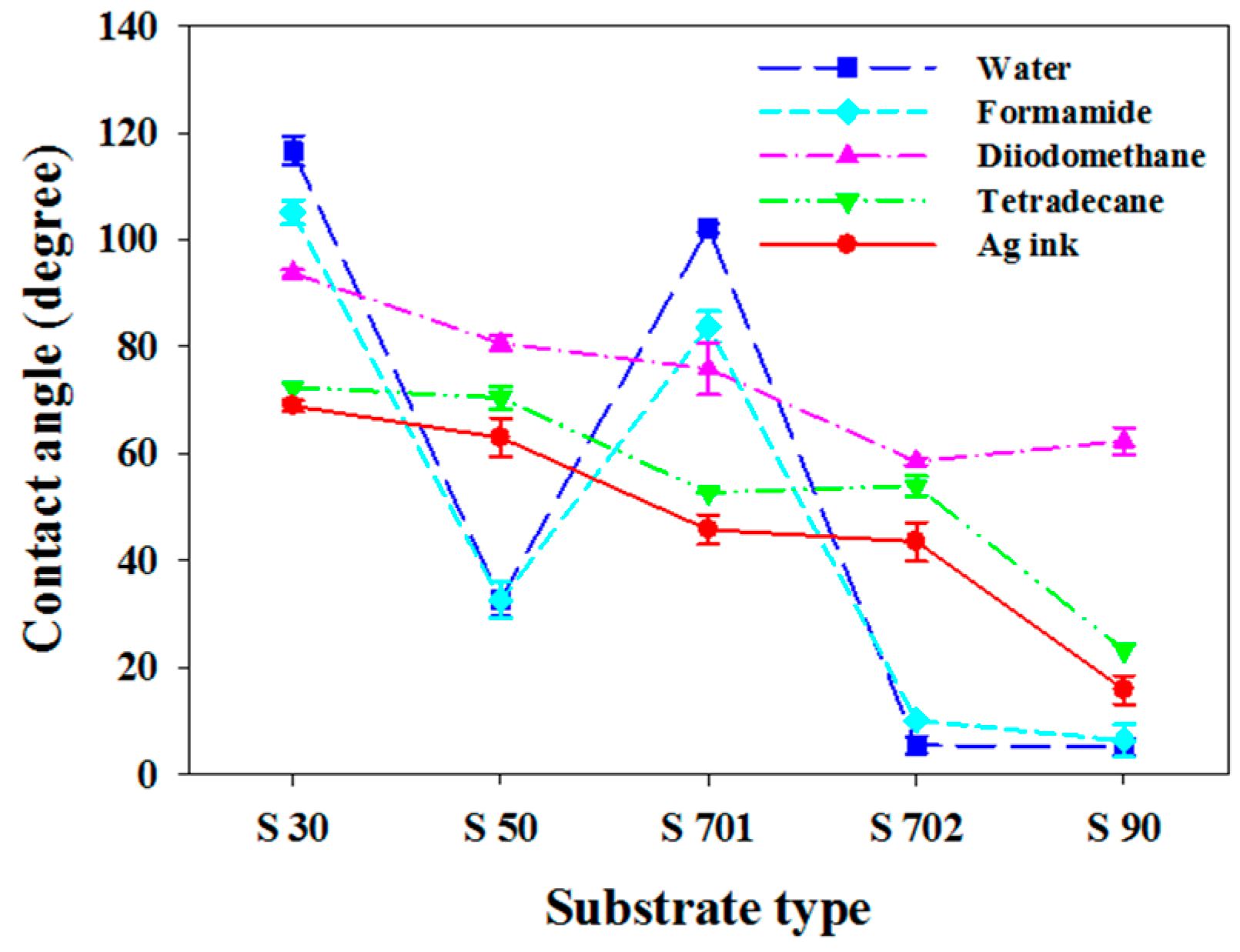
Contact angles are measured for each plasma-treated substrate using an optical contact angle analyzer (Phoenix 300, Surface Electro Optics Co., Ltd., Suwon, Gyeonggi-do, Korea). The five test liquids used for the measurement are as follows: two polar liquids (water and formamide (Sigma-Aldrich Corp., St. Louis, MO, USA)), two non-polar liquids (diiodomethane (Sigma-Aldrich Corp., St. Louis, MO, USA) and tetradecane (Sigma-Aldrich Corp., St. Louis, MO, USA) and a tetradecane based Ag colloidal suspension. Figure 2 presents the results of the contact angle measurement. Between the polar-liquids and the non-polar liquids, the fluctuation of contact angles was more dominant in the former than the latter. Moreover the contact angle decreased overall as the substrate type varied from a hydrophobic S 30 to a hydrophilic S 90. Among the substrates, the S 30 showed the largest contact angle for all the test liquids. Particularly the S 701 had much larger contact angle than the S 50 and the S 702 substrate, deviating from the general trend. This anomalous behavior will be explained in terms of the surface characteristics of the substrates in the following.
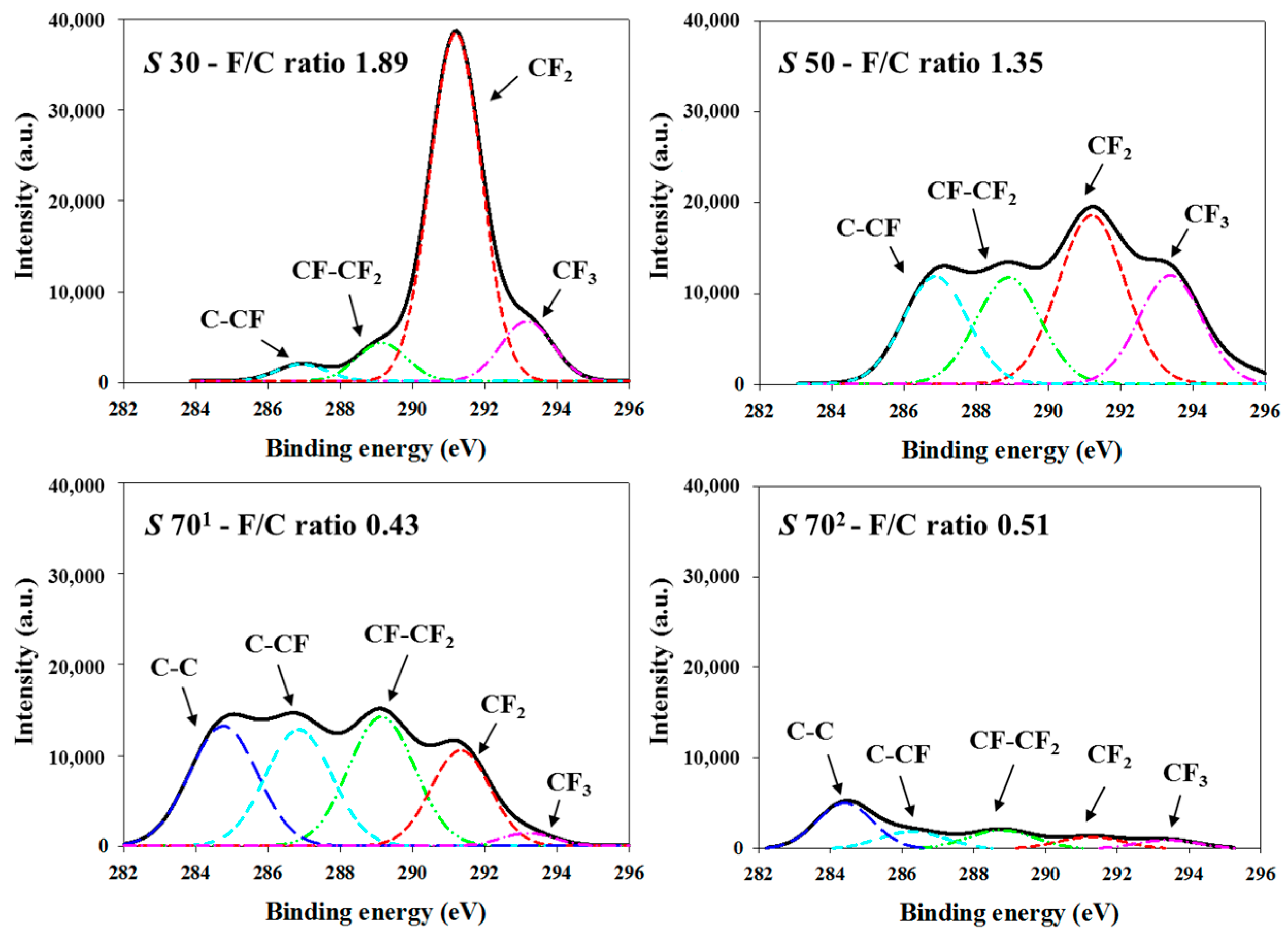
Figure 3 presents the high-resolution XPS spectra of C1s core level of the fluorocarbon polymeric film deposited on the other substrates except the S 90. The C1s spectra were decomposed into five components to determine the chemical composition of the film-coated substrate surfaces: C-C (284.6 eV), C-CF (286.6 eV), CF-CF2 (288.9 eV), CF2 (291.2 eV) and CF3 (293.3 eV). The S 30 substrate contained a larger amount of C-Fx moieties than the S 50 and S 70 substrates. Also the intensity of the C-Fx moieties decreased as the hydrophilicity of the plasma-treated substrate increased. The C-C bond began to appear in the chemical composition of the two S 70 substrates because of the defluorination induced by the O2 plasma etching which eliminates the CF2 and CF3 species. The F/C ratio of each substrate decreased from 1.89 to 0.43. This is in good agreement with the overall transition of the measured contact angles.
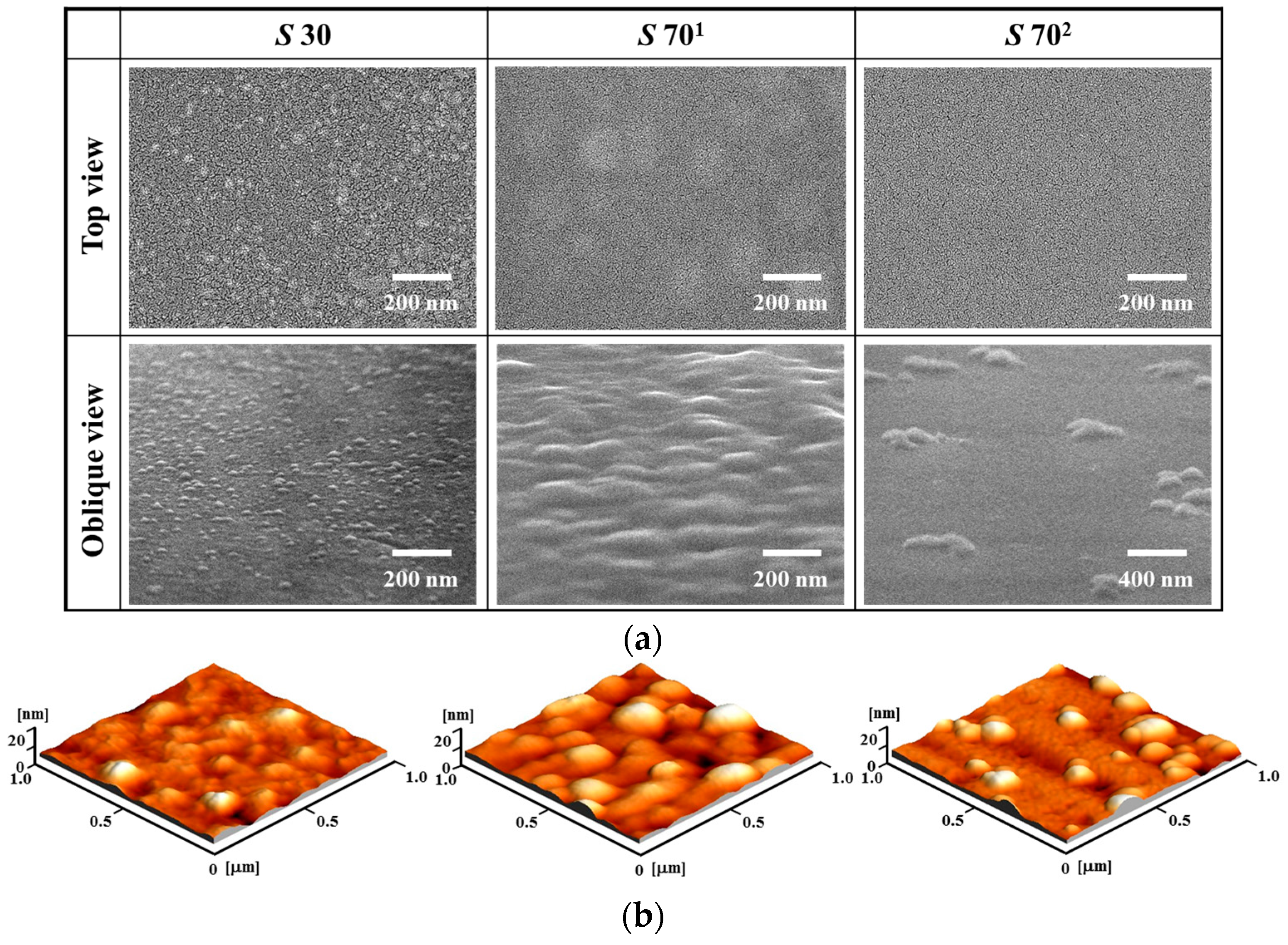
The surface topology after the plasma surface treatment was examined using SEM and AFM, as in Figure 4. The SEM images and the corresponding AFM images present that the S 701 and the S 702 possess a remarkable difference in the surface topology although they have the similar droplet diameter and F/C ratio. The S 701 substrate has numerous hillocks on the fluorocarbon film, compared to the S 702 substrate. However, the difference of the surface roughness does not seem to make the difference in contact angle between the two substrates because it cannot explain the difference of contact angle between the polar and non-polar liquid shown in Figure 2. Hence, probably the anomalously large contact angle on the S 701 would occur due to the surface polarity which is deeply correlated with the chemical composition of the substrate. The S 701 has a similar F/C ratio with the S 702, but shows a considerable difference in the intensity of the chemical species contained in the XPS spectra.

3.2. The Instabilities of Inkjet-Printed Lines

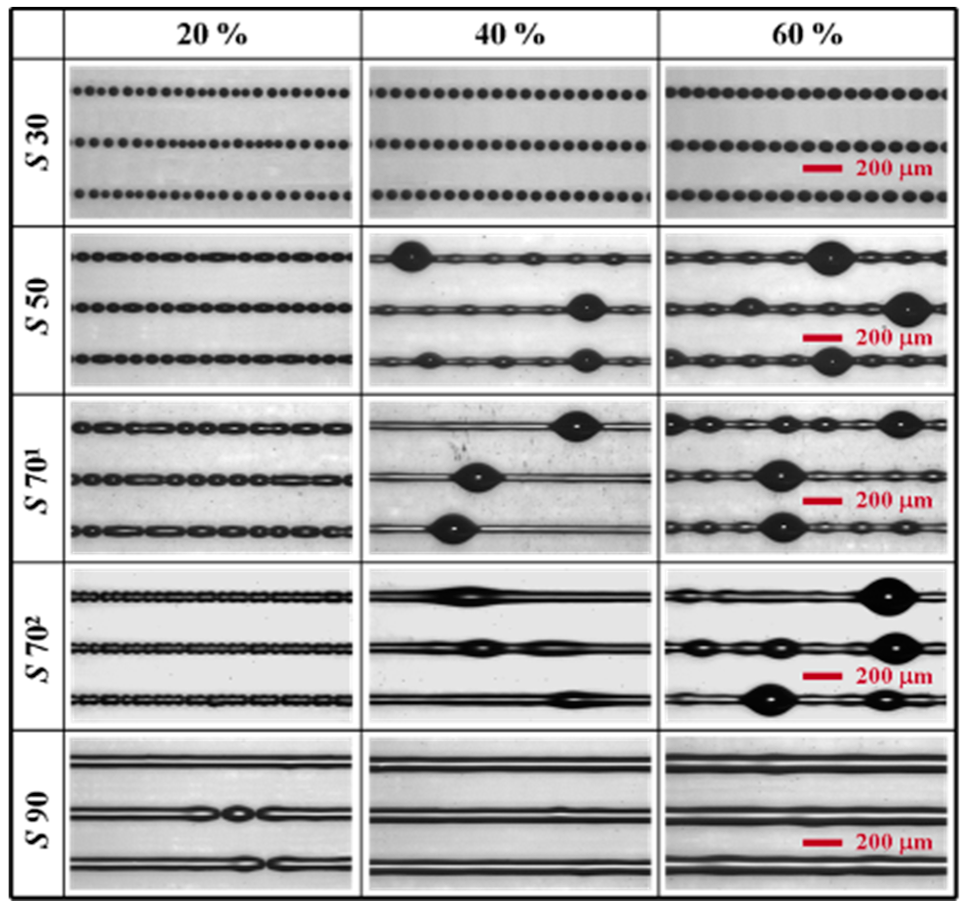
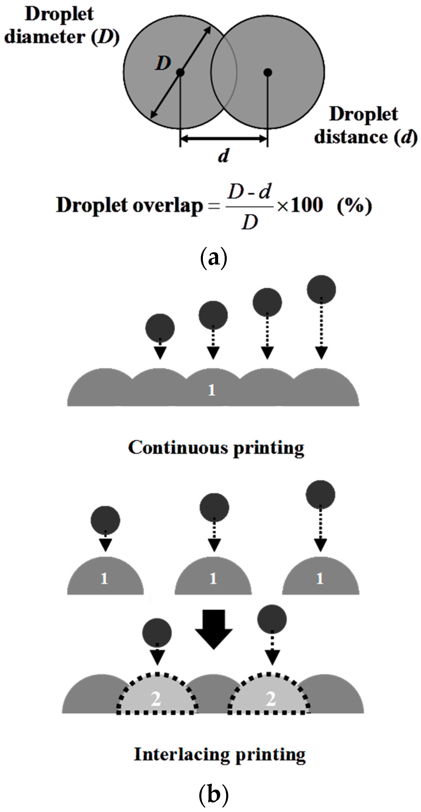
By continuous printing procedure, inkjet lines were printed on the five substrates with 200 Hz printing frequency at room temperature (Figure 5). The overlap ratio between neighboring droplets was adjusted to 20%, 40% and 60%. On the hydrophobic S 30 substrate, most of the printed droplets maintained their circular liquid patterns without forming any continuous inkjet lines for all the overlap ratios. The droplets returned into the separated circular configuration as soon as deposited on the substrate surface and accordingly, the merging of the droplets occurred immediately from the beginning of inkjet printing. The size of the circular patterns increased due to the increase of ink amount merged, as the overlap ratio increased. On the S 50 to the S 70 substrate, a train of bead-like liquid patterns was observed at 20% overlap ratio. When the overlap ratio increased to 40%, the bead-like patterns transformed into the continuous lines where many bulges are regularly distributed along the line. The size of the individual bulges connected by liquid ridges got larger when increasing the overlap ratio from 40 to 60%. The formed bulges are observed to be more prevalent on the S 50 substrate than the S 70 substrates under the same overlap ratio. Besides, when comparing the S 701 and the S 702 each other, the bulges on the latter substrate are more irregular and less appeared than ones on the former substrate, in spite of their similar dried droplet diameters. This attributes to the difference in the wetting characteristics of the ink on the substrates, which are primarily governed by the chemical nature of the substrate surface such as F/C ratio and surface polarity. Besides the ink in the transition regime from spherical (i.e., droplet) to cylindrical shape (i.e., line) are more influenced by the former than the latter. On the hydrophilic S 90 substrate, stable straight lines were printed at 40% and 60% overlap ratios. This is related to the large spreading of ink droplets on the substrate. The outflow of ink in the droplets reaches farther for the conservation of line volume and accordingly, the possibility of bulge formation becomes very low. It helps the uniform and wide spreading of the ink droplets when they meet to produce straight lines.
According to the previous researches regarding with bulging instability, the appearance frequency of bulges decreases by increasing either the droplet spacing or the time interval between droplet landings when printing liquid lines with zero receding contact on a homogeneous surface. However it is opposite to what was confirmed in Figure 5. Stable inkjet lines could not be obtained on 
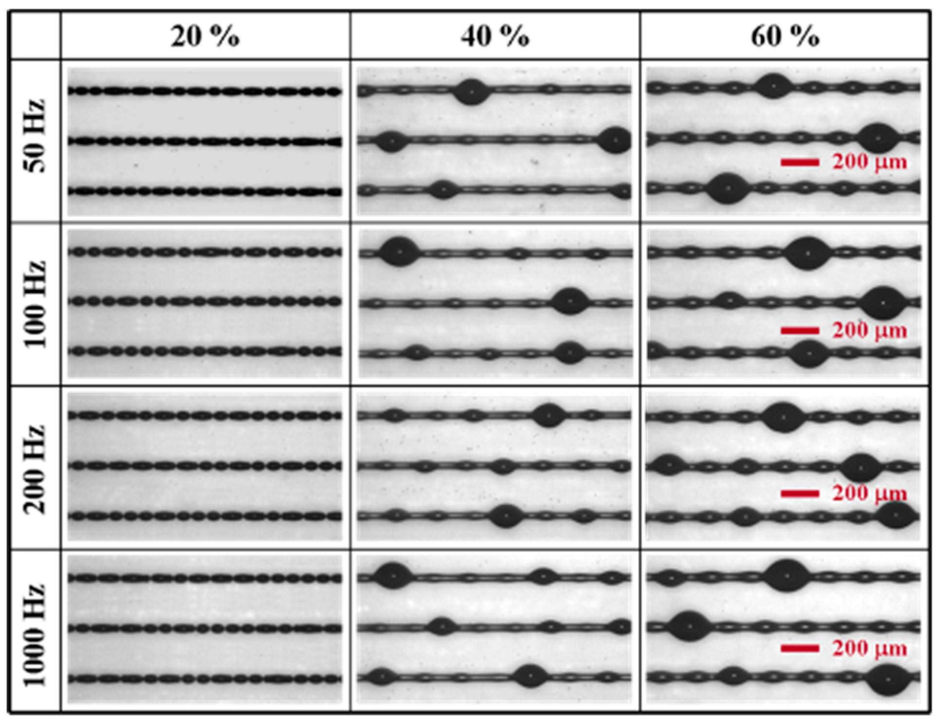
S 70 substrates even at low droplet overlap. The recognition about the inconsistency with the previous reports led to investigating the effect of printing frequency on bulging instability additionally. The investigation was performed on S 50 substrate by changing the frequency from 50 to 100 Hz for various droplet overlaps at 125 °C (Figure 6). The lower printing frequency yields a larger time interval between successive droplet landings at a fixed droplet overlap. The result is given in Figure 6. It demonstrates that the printing frequency has little effect on the bulge formation in terms of the size and the appearance frequency of bulges.
According to Duineveld’s work, inkjet-printed lines with significant hysteresis between advancing and receding contact angle (CA), i.e., θa and θr, become unstable, forming either a train of merges or regular bulges [25]. The requisite for the bulging instability is that liquids should have a zero θr and an initial CA (θi) larger than θa. Generally a colloidal suspension containing small-sized particles is said to have a zero θr because its contact line can advance but can’t retreat due to the contact line pinning by particle deposition during solvent evaporation. For that reason, ink on a substrate spreads until the θi decreases down to the θa due to capillary force, forming an outward-moving contact line.
Going back to Figure 5 and Figure 6 with the above explanation, the inkjet lines on S 30 substrate do not wet the substrate surface, breaking up into separate circular droplets and forming inward-moving contact lines. It occurs because the ink has both the θi and the non-zero θr, which are close to θa. However, the ink on S 50 to S 70 substrates was initially expected to have a zero θr and the θi larger than 
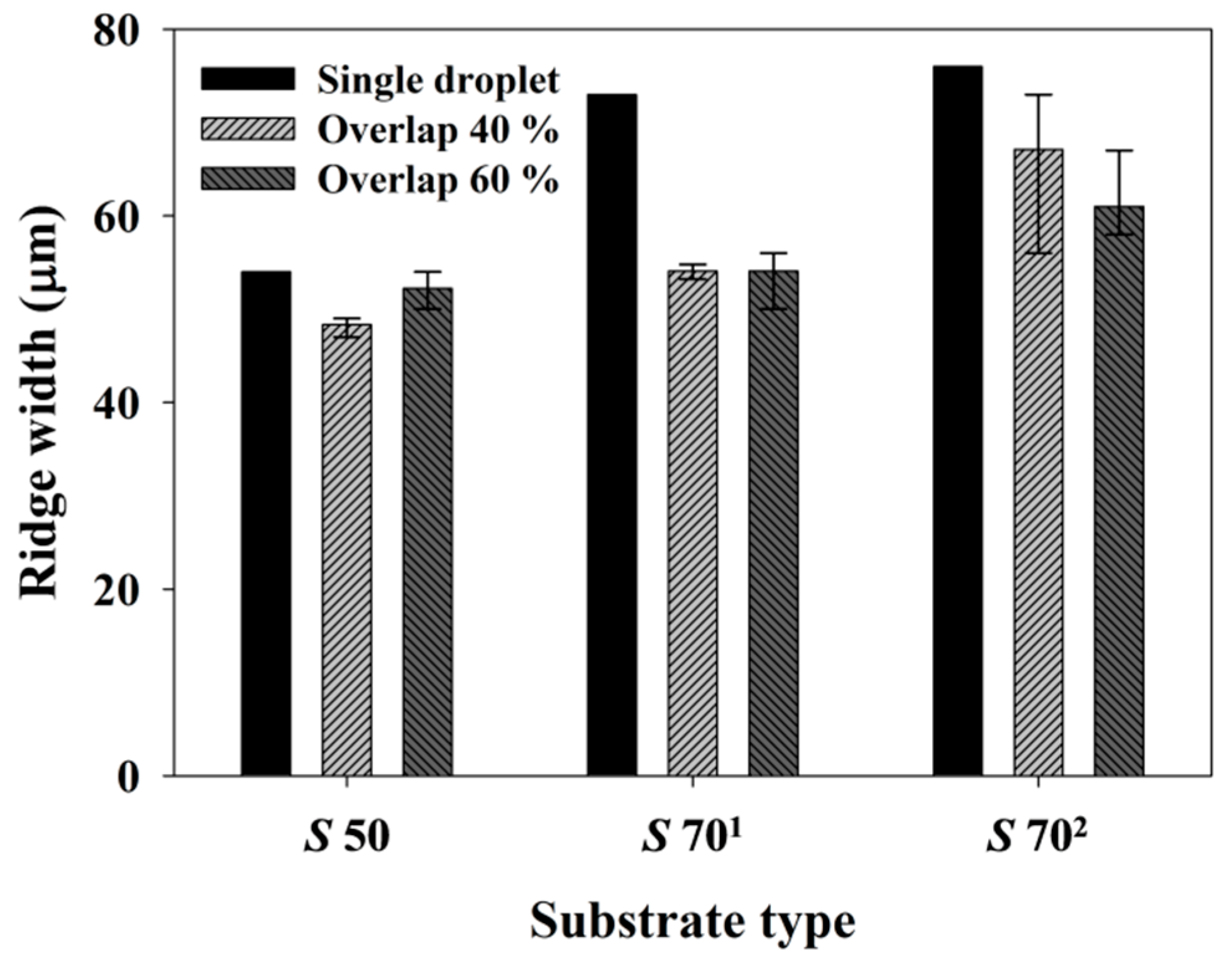
θa, since the substrates yielded the liquid lines with a series of bulges. However the ridges observed from the lines have a smaller width than a single droplet diameter because of the liquid dewetting (Figure 7). It indicates that the Ag colloidal ink on the substrates had a non-zero θr at the initial stage of the line formation, and the non-zero θr resulted in bulge formation. This shows that bulging phenomenon can occur even with a non-zero θr for a relatively long time until the contact line is pinned and the θr becomes zero. It caused the inconsistency of bulge formation process with the previous researches, like confirmed in Figure 5 and Figure 6.
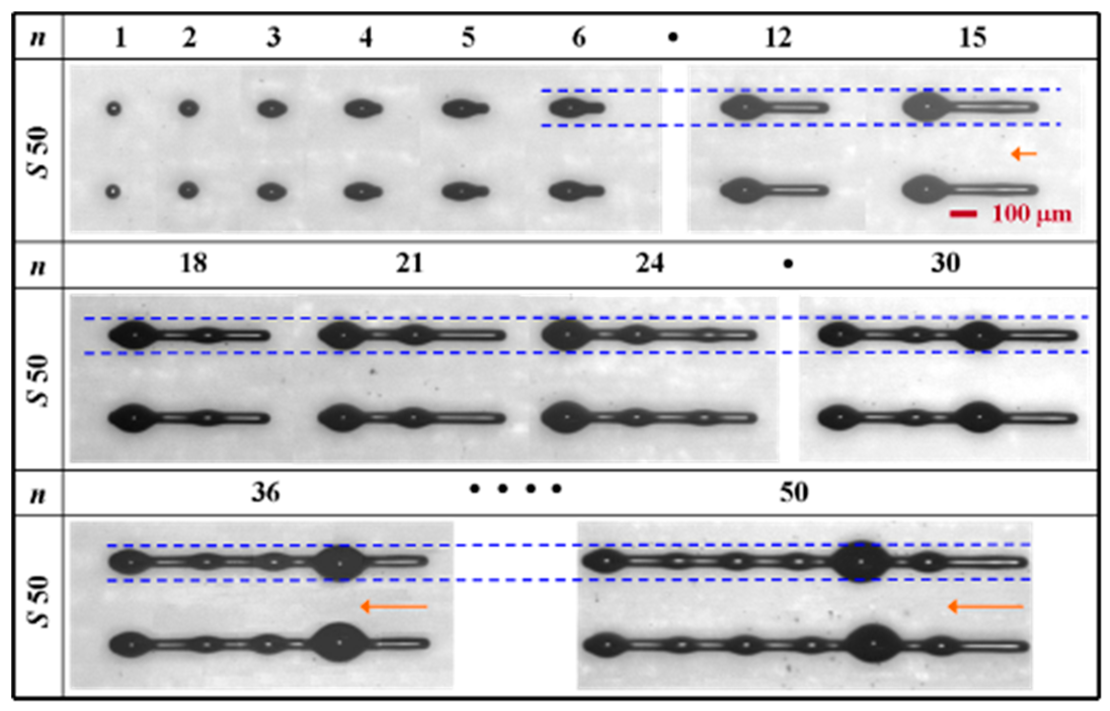
Figure 8 shows the growth of bulges and ridges on S 50 substrate with the number of printed droplets (n). The experiment was performed by providing ink droplets toward right direction with 40% droplet overlap at room temperature. First, note that all cases in the figure are the results obtained from separate printings. The end of a liquid line, where ink droplets are deposited, moves continuously toward right side as n increases. This brings a different end effect in each printed line. When n ≤ 3, the second and third droplets retreat from their initial landing positions toward the first droplet site, immediately after the deposition. Then, they form the liquid pattern in a large elliptical dome shape, minimizing their surface energy. Here the first bulge is initiated. Next, the ridge of the liquid pattern starts to pull out from when depositing the fourth droplet (n = 4). The length of the ridge increases steadily till printing the fourteenth droplet on the substrate. At the same time with the growth of the ridge, the first bulge also develops with n until reaching the equilibrium width determined by θa. The primary cause of the bulge growth is in pressure-driven fluid transport between the bulged front and the end of the narrow liquid line. The amount of the fluid delivered to the bulge through the ridge decreases as the length of the liquid line increases by printing, because the pressure difference between the two approaches to zero gradually. However after the routine landing of the droplets, fluidic disturbance arises due to the large curvature which is made at the end of the line and which in turn leads to the creation of a second bulge. The formation process of the second bulge can be physically explained by the relationship of two kinds of a fluid flow existing along the line: capillary spreading and liquid addition by printing. When printing ink droplets under equilibrium status, the volume of the ink moving toward the line end by capillary force is smaller than one supplied by the printing. The unbalance of the two volume flows produces a large curvature on the line end, together with extra pressure. The extra pressure makes the ink flow short distance from the line end, resulting in the formation of the second bulge. Due to such mechanism, a new bulge appears abruptly between the first bulge and the line end at n = 15. Exceeding the number of ink droplets over 15, the injected ink begins to flow toward the second bulge and accordingly, the size of the second bulge becomes larger. After the second bulge grows large enough to induce pressure equilibrium in the liquid line, the initiation of the third bulge occurs in the same procedure explained above, i.e., at n = 24. When more than 30 ink droplets are deposited, there is observed an interesting phenomenon in terms of the size of bulges. Among the bulges developed along the printed line, the latest bulge is largest. The irregularity of the bulge sizes occurs because of the liquid accumulation resulted from the instantaneous breaking of the pressure balance in left and right side of the latest bulge, i.e., between the latest bulge and the previous bulges, and between the latest bulge and the line end. For example, initially the third bulge shows a similar formation and growth process with the first and second bulges, till reaching the pressure balance between the third bulge and the line end. Afterwards, the contact line of the third bulge collapses suddenly while printing ink droplets and accordingly, a pressure drop occurs at the location of the third bulge. It results in the simultaneous inflow of ink into the third bulge from both the previous bulges and the line end, making its size largest. The fourth and fifth bulges in Figure 8 also go through the same procedure of the size growth.
In order to fabricate narrow inkjet lines, the surface energy of substrates should be low. However the hydrophobic S 50 substrate, which is prepared by single C4F8 plasma, has a non-zero θr that makes difficult obtaining stable narrow liquid lines through the control of printing variables because of inducing bulging instability. In order to prevent the non-zero 
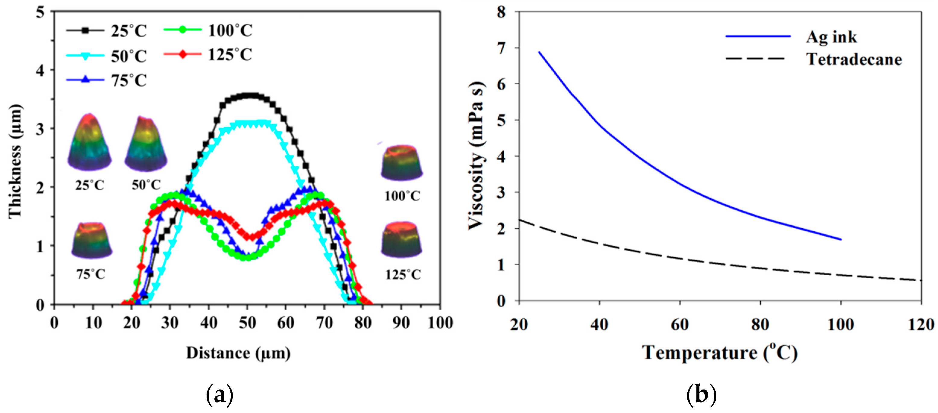
θr from hindering the fabrication of stable inkjet lines, the surface temperature of substrates needs to be increased. It is to facilitate the drying of ink liquid faster than the propagation of the bulge instability. This study investigated the effect of the substrate temperature on printed line morphology. It was performed by measuring the cross-sectional profiles of the dried single droplet produced on S 50 substrate for various temperatures ranging from room temperature to 125 °C (Figure 9). The 3D images corresponding to each profile also are given in the figure, together with the viscosity variation of Ag colloidal suspension with temperature. At temperatures of 25 °C and 50 °C, stable pattern of a dried single droplet is obtained in an inverse parabolic shape. However for the temperatures exceeding 50 °C, a ring-like distribution of dried particles, so-called coffee ring effect, is observed from the profiles. It is created by the outward flow of the colloidal suspension replenishing the evaporation loss at a contact line. The coffee ring effect becomes stronger as T increases, because of the combined effect of enhanced evaporation rate at a droplet edge and contact line pining at high temperature. The change of the ink viscosity with temperature also would affect the ring-like pattern. In the Figure 9, it is observed that the dried droplet diameter increases weakly along with temperature. Meanwhile, the volume of the dried ink droplet decreases with the temperature. It can be explained as follows: The ink droplet dried at room temperature contains both tetradecane solvent not evaporated yet and air void inside it. As the substrate temperature increases, the evaporation of the remaining solvent occurs actively and also the number of the voids decreases significantly. Finally the ink droplet becomes to have a concave peak, together with the reduced volume.
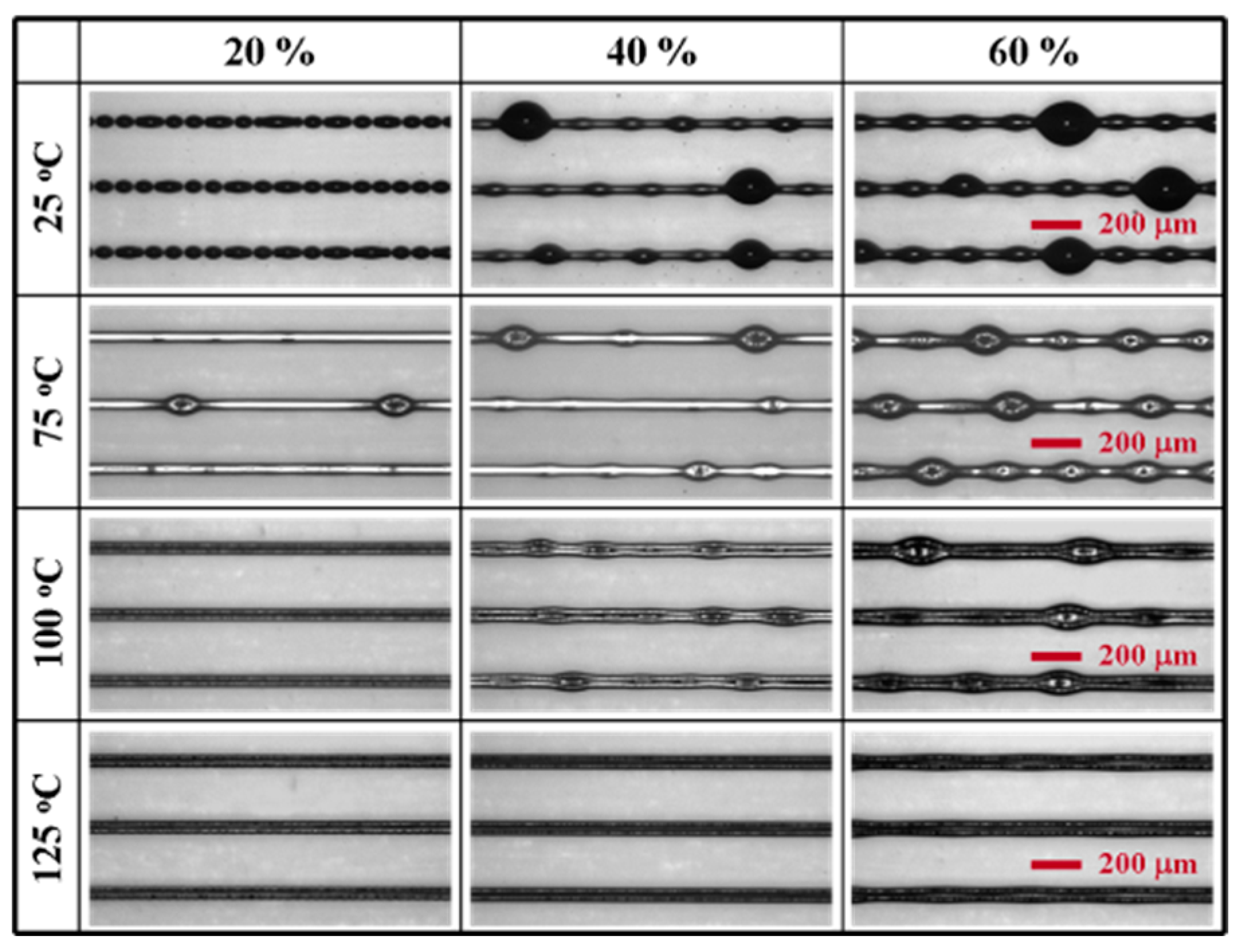
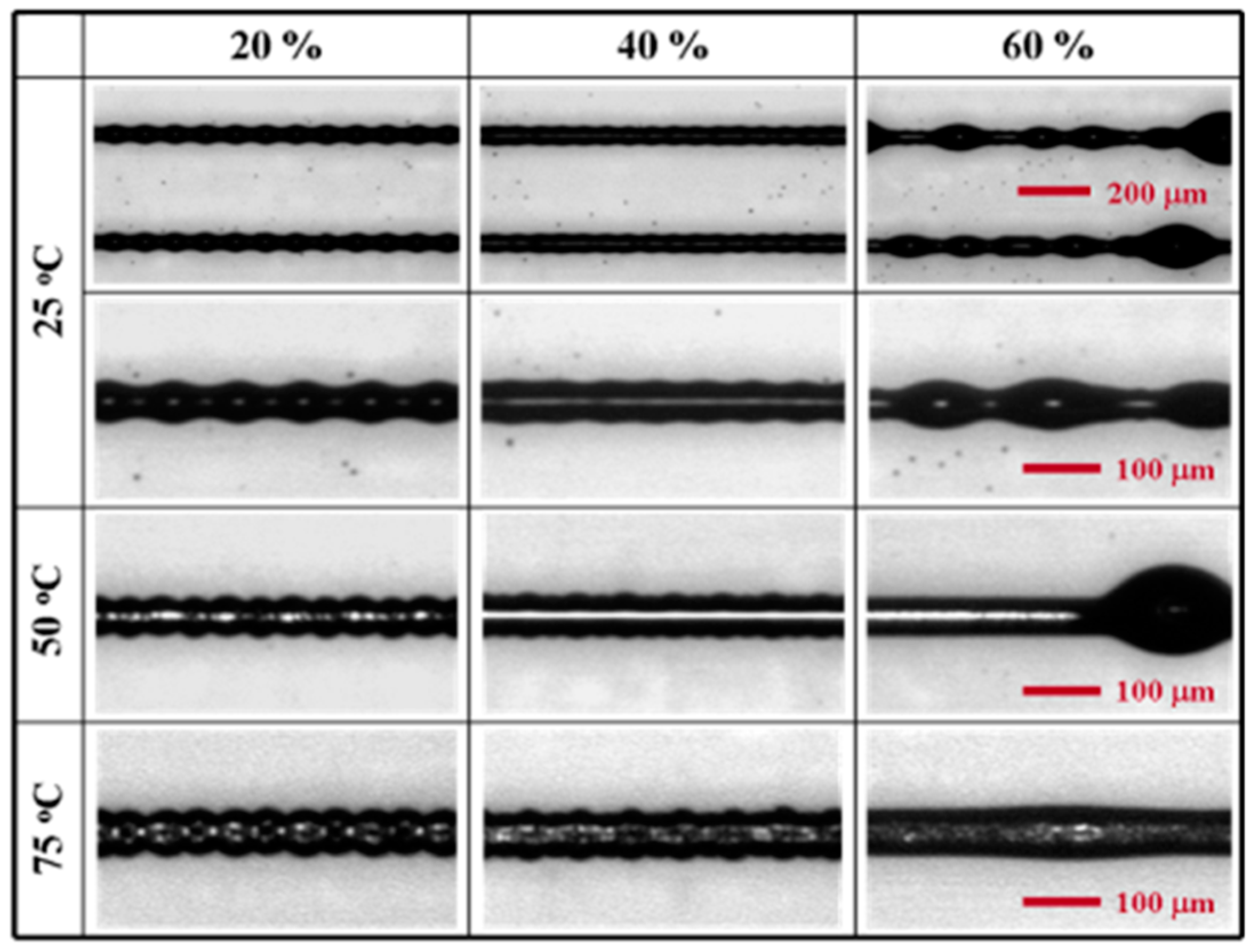
In addition to the morphology transition of an ink droplet with temperature, the change of the morphology of inkjet-printed lines on S 50 substrate along with printing modes was investigated for various droplet overlaps and temperatures. The results by continuous printing procedure are shown in Figure 10. When temperature is increased to 75 °C, continuous lines are produced without break-up at low overlap ratio, i.e., 20% and the bulging instability becomes diminished at higher overlap ratios. The reason that the bulges still exist at T = 75 °C is because the inkjet lines retain a liquid state at the given T. The individual droplets become solidified at a rate much slower than the printing speed. However at T = 125 °C, stable inkjet lines are produced on S 50 substrate for all the overlap ratios. On the contrary, at T = 100 °C the inkjet lines not containing bulges are obtained only at the low overlap ratio of 20%. The formation of bulges suppressed at higher T attributes to the reduction of ink flowing into each bulge through ridges, which is a direct consequence of the rapid solidification of individual droplets. For the three temperatures, coffee ring effect also is confirmed from all the inkjet lines.
Figure 11 shows the patterns of inkjet lines printed by interlacing printing procedure. Each inkjet line was produced by at least two printing sequences. The morphology of the lines was investigated under the similar conditions with the continuous printing procedure except the temperature range limited below 75 °C. The reason of using the downward-adjusted temperature range was to stably produce inkjet-printed lines with narrower width in the printing procedure. With 20% and 40% overlap ratios at room temperature, stable continuous lines with a non-zero θr were printed on the S 50 substrate. This is obtainable because of the discontinuous nature of the interlacing printing procedure. Under the mode, the ink flow is not enough to introduce hydrodynamic instability in the printed lines. The inkjet lines become unstable with the irregular sizes of bulges at 60% overlap ratio. During the first pass of interlacing printing procedure, the incomplete but partially continuous lines are formed due to the high overlap ratio. They are subject to the pressure difference causing the formation and growth of a bulge during the second pass. In order to examine the effect of temperature on the interlacing mode-printed lines, the surface of S 50 substrate was gradually heated from room temperature to 75 °C. As temperature increases, the solidification of individual ink droplets proceeds faster than the printing period between the first and second pass, leaving the distinct round edge on the substrate. The appearance frequency of bulges also decreases along with the temperature increase, due to the rapid evaporation of solvent.

3.3. Thickness-Enhanced Inkjet Lines by Overprinting

Increasing the thickness of inkjet-printed lines needs the overprinting of a number of ink layers on top of each other. In the overprinting process, temperature condition is a critical factor since it changes the solidification rate of ink droplets before their spreading by increasing a solvent evaporation rate. The proper control of temperature enables the buildup of ink layers without their flowing down. Therefore, this study explored the ways to stably produce thick inkjet-printed lines with narrow width. The experiment was performed on S 50 substrate heated to T = 125 °C and each ink layer was printed every 2 min on the substrate. First, overprinting by continuous printing procedure was attempted. It was sequentially performed by increasing 
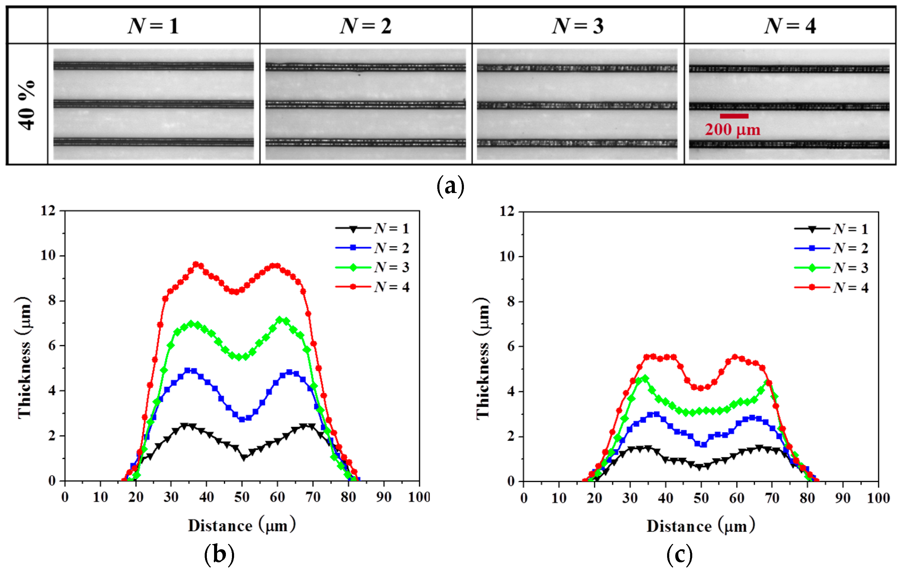
N from 1 to 4 at 40% overlap ratio (Figure 12a). The morphology of the resulting silver lines was investigated by measuring the cross-sectional profiles after drying (Figure 12b) and after sintering (Figure 12c) respectively and comparing them each other. According to the measurement, there is almost no increase of the line width during the overprinting (N ≥ 2). This is because the overprinted droplets were dried on the substrate heated to 125 °C before their spreading. If an ink flow occurred throughout the overprinting, the width of the inkjet-printed lines would increase with the number of printings (N). The spreading of the deposited droplets is also greatly influenced by the surface morphology of as-printed lines. The smooth and concave surface of as-printed lines helps stable landing and stacking of ink droplets. The combination of these effects enabled the successful printing of the stack-like geometry with ~9 μm thickness and ~70 μm width at N = 4. However, coffee ring effect was observed from all morphologies of the printed lines. Figure 12c shows the morphology change of the lines after sintering. The inkjet lines experienced a significant decrease of thickness after 1 h heating at 220 °C in furnace. It is due to the aggregation and densification of the Ag nanoparticles along with grain growth, and the decomposition of organic additives within the ink. The coffee ring effect became more dominant because of the central collapse which was resulted from the movement of the silver particles toward the contact line during the sintering.
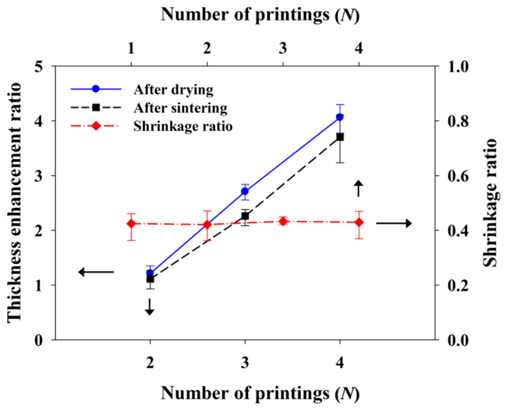
For further details, the change of thickness of the overprinted lines by each of the drying and the sintering, and the coffee ring effect were re-evaluated in terms of three parameters: (1) thickness increase ratio; (2) vertical shrinkage ratio and (3) valley-to-peak ratio. The results are given in the Figure 13 and Figure 14. The first ratio of the overprinted lines increased linearly with 
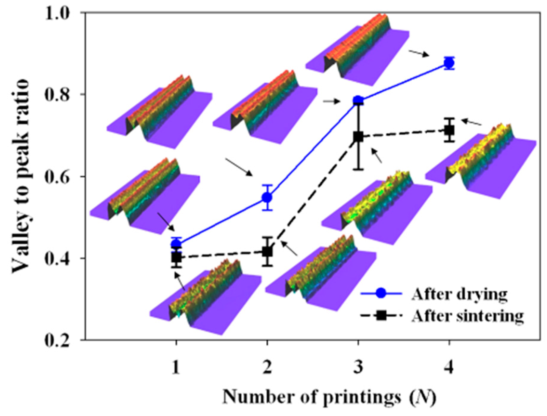
N for both the two processes, due to the stacking behavior of the lines. The second ratio was constant regardless of the overprinting, since the densification of Ag nanoparticles in the ink occurred in all the stratified lines during the sintering process. Additionally, the surface non-uniformity of the inkjet-printed lines by coffee ring effect was also investigated by calculating the change of the third ratio with the overprinting (Figure 14). As N increased, the value of the valley-to-peak ratio increased too. It presents that the surface of the inkjet-printed lines could get uniform through the overprinting even at the high substrate temperature. The valley-to-peak ratio after the sintering was overall lower than after the drying, indicating that the coffee ring effect became more dominant due to higher shrinkage at the middle surface region. The 3D insets of the inkjet lines in Figure 14 support the distinction of the surface non-uniformity through the valley-to-peak ratio.
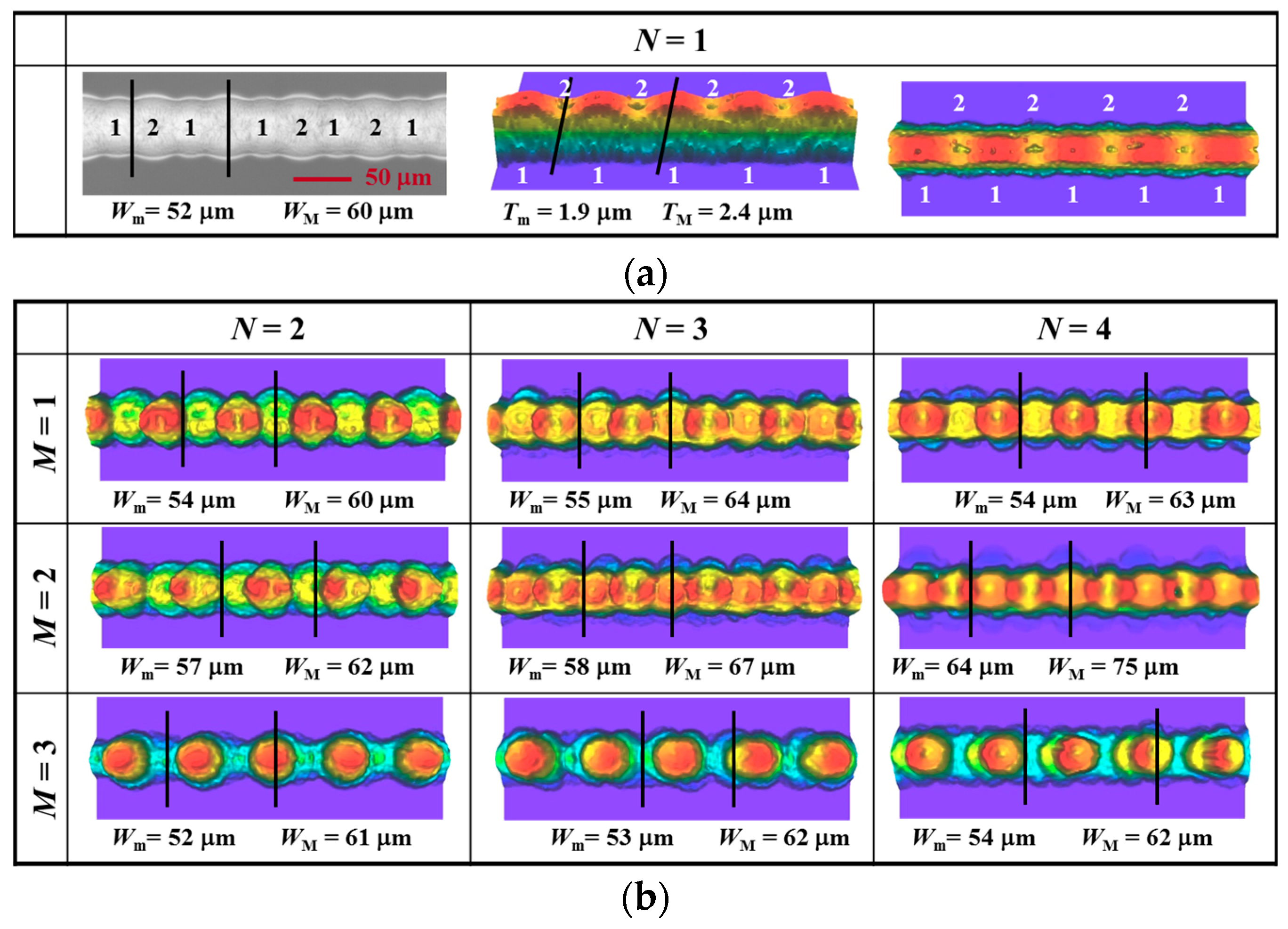
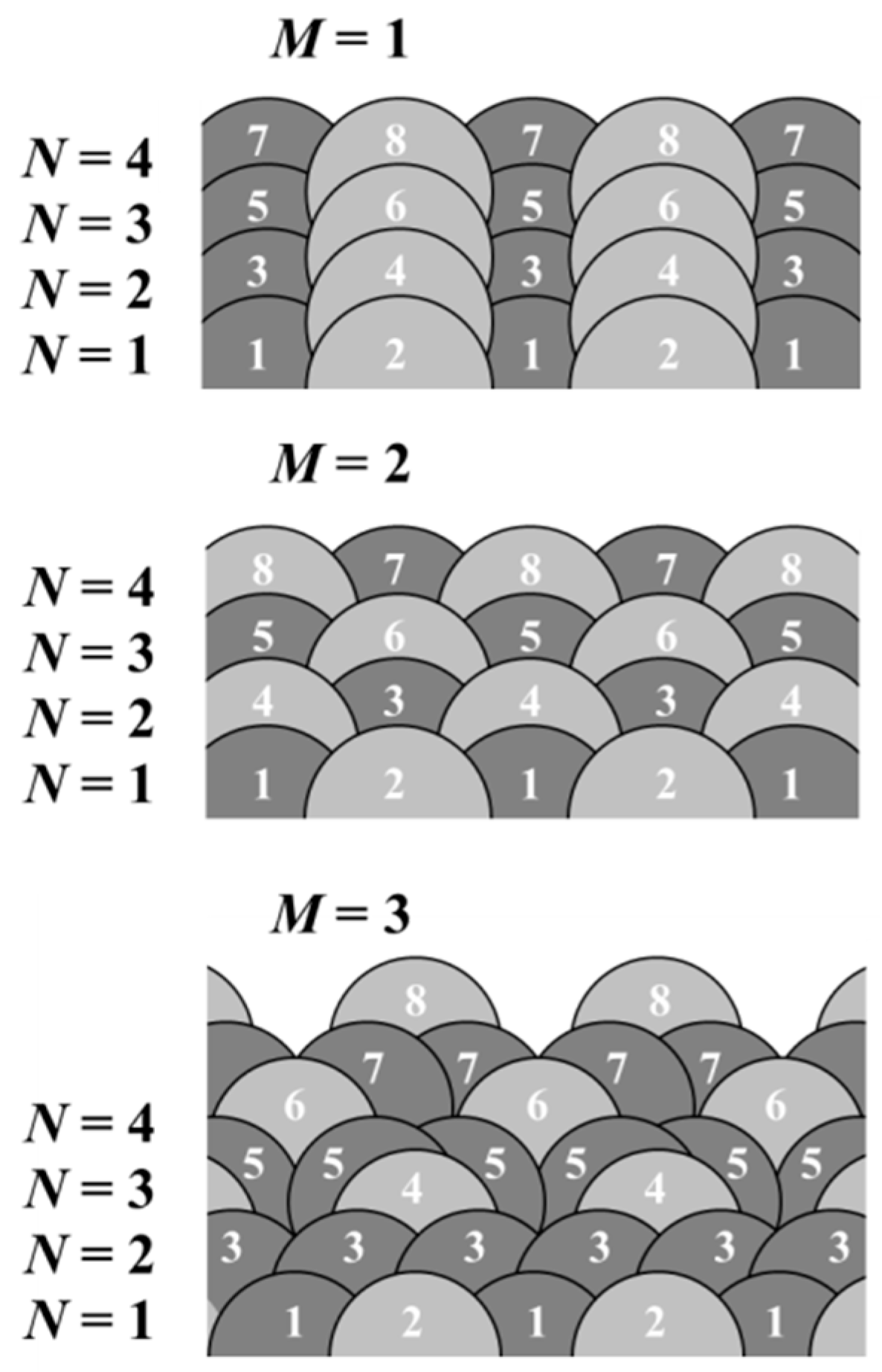
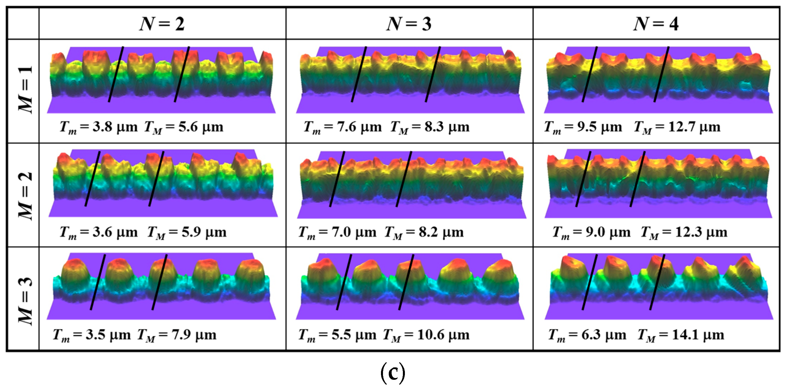
Figure 15 illustrates various printing modes of interlacing procedure. Each of the modes can be chosen for the improvement of geometrical characteristics of printed lines. Therefore, we investigated the change of the shape and morphology of intertwined printed lines with the modes by performing overprinting up to four times on S 50 substrate heated to 75 °C. The result is shown in Figure 16. The first layer (N = 1), a base layer for all the modes, was printed in the same manner as seen in Figure 11. It has an undulated surface profile with non-uniform thickness and bad edge sharpness, because of the multiple-pass printing nature of the interlacing procedure and the fast evaporation of the ink solvent (Figure 16a). The geometrical characteristics directly affected the following overprintings (Figure 16b,c). At N ≥ 2, the waved line edge became more prominent along with the N and hence, showed a considerable height variation across the line width for all of the printing modes. In the comparison of each mode, there was not observed a significant difference of a geometric profile between M1 and M2. However, relatively the former showed better line features than the latter, e.g., a narrower line width for the similar thickness variation. Unlike the two modes, M3 produced inkjet-printed lines with tooth-like configuration and moderating the boundary between each ink droplet. It is because the mode deposited ink droplets denser at the first pass of the overprinting, compared to the other two modes. Lastly the coffee ring effect was less developed in the interlacing printing procedure than the continuous printing procedure shown in Figure 12.

4. Conclusions

In this paper, the geometrical characteristic and the fluid instability of inkjet-printed lines with non-zero receding contact angle on plasma-treated substrates were examined in terms of various printing variables. For the study, a colloidal suspension containing 56 wt % silver nanoparticles in tetradecane solvent was used as printing ink. The substrates were obtained by performing a PECVD process with C4F8 and O2 under multiple treatment conditions. The printing variables included surface energy, droplet overlap ratio, printing frequency, a number of ink droplets, substrate temperature and printing procedures. The change of surface morphology of the printed Ag lines with the parameters demonstrated that the surface energy of a substrate has great influence on the stable formation of inkjet lines with non-zero receding contact angle. The bulging instability of the lines was developed in the competition of capillary spreading and liquid flow supplied by printing. It decreased by increasing the surface temperature of a substrate, regardless of printing frequency and droplet overlap ratio. The comparison of continuous and interlacing procedure showed that at room temperature and <40% droplet overlap ratio, the latter produces the Ag inkjet lines in a more stable pattern on a hydrophobic substrate. Moreover, the interlacing procedure was also more advantageous to fabricate thick and narrow Ag lines with well-defined configuration. These experimental findings will provide invaluable insights to the production of various printed electronics containing high-aspect-ratio structures.

Acknowledgments

This work was supported by the National Research Foundation of Korea (NRF) grant funded by the Korea government (MSIP) (No. 2016R1A2B4009305). Also it was supported by Basic Science Research Program through the National Research Foundation of Korea (NRF) funded by the Ministry of Education (No. 2016R1D1A1B03934976).

Author Contributions

J.-S.K. and J.H.O. conceived and designed the experiments; J.-S.K. and D.J.L. performed the experiments; J.-S.K., D.J.L. and J.H.O. analyzed the data; J.-S.K. and D.J.L. contributed reagents/materials/analysis tools; J.-S.K., D.J.L. and J.H.O. wrote the paper.

Conflicts of Interest

The authors declare no conflict of interest.

References

  1. Kang, B.J.; Lee, C.K.; Oh, J.H. All-inkjet-printed electrical components and circuit fabrication on a plastic substrate. Microelectron. Eng. 2012, 97, 251–254. [Google Scholar] [CrossRef]
  2. Kang, B.J.; Oh, J.H. Control of the crystalline structure of inkjet-printed semiconductor layers using overlap condition and surface wettability. J. Micromech. Microeng. 2015, 25, 055011. [Google Scholar] [CrossRef]
  3. Jang, S.; Lee, D.J.; Lee, D.; Oh, J.H. Electrical sintering characteristics of inkjet-printed conductive Ag lines on a paper substrate. Thin Solid Films 2013, 546, 157–161. [Google Scholar] [CrossRef]
  4. Sirringhaus, H.; Kawase, T.; Friend, R.H.; Shimoda, T.; Inbasekaran, M.; Wu, W.; Woo, E.P. High-resolution inkjet printing of all-polymer transistor circuits. Science 2000, 290, 2123–2126. [Google Scholar] [CrossRef] [PubMed]
  5. Jang, S.; Kim, Y.; Oh, J.H. Influence of processing conditions and material properties on electrohydrodynamic direct patterning of a polymer solution. J. Electron. Mater. 2016, 45, 2291–2298. [Google Scholar] [CrossRef]
  6. Gans, B.-J.D.; Duineveld, P.C.; Schubert, U.S. Inkjet printing of polymers: State of the art and future developments. Adv. Mater. 2004, 16, 203–213. [Google Scholar] [CrossRef]
  7. Calvert, P. Inkjet printing for materials and devices. Chem. Mater. 2001, 13, 3299–3305. [Google Scholar] [CrossRef]
  8. Cummins, G.; Desmulliez, M.P.Y. Inkjet printing of conductive materials: A review. Circuit World 2012, 38, 193–213. [Google Scholar] [CrossRef]
  9. Singh, M.; Haverinen, H.M.; Dhagat, P.; Jabbour, G.E. Inkjet printing—Process and its applications. Adv. Mater. 2010, 22, 673–685. [Google Scholar] [CrossRef] [PubMed]
  10. Mogg, B.T.; Claypole, T.; Deganello, D.; Phillips, C. Flexographic printing of ultra-thin semiconductor polymer layers. Transl. Mater. Res. 2016, 3, 015001. [Google Scholar] [CrossRef]
  11. Chiolerio, A.; Rivolo, P.; Porro, S.; Stassi, S.; Ricciardi, S.; Mandracci, P.; Canavese, G.; Bejtkaa, K.; Pirri, C.F. Inkjet-printed PEDOT:PSS electrodes on plasma modified PDMS nanocomposites: Quantifying plasma treatment hardness. RSC Adv. 2014, 4, 51477–51485. [Google Scholar] [CrossRef]
  12. Rajan, K.; Roppolo, I.; Chiappone, A.; Bocchini, S.; Perrone, D.; Chiolerio, A. Silver nanoparticle ink technology: State of the art. Nanotechnol. Sci. Appl. 2016, 9, 1–13. [Google Scholar] [CrossRef] [PubMed]
  13. Wang, J.Z.; Zheng, Z.H.; Li, H.W.; Huck, W.T.S.; Sirringhaus, H. Dewetting of conducting polymer inkjet droplets on patterned surfaces. Nat. Mater. 2004, 3, 171–176. [Google Scholar] [CrossRef] [PubMed]
  14. Kang, B.J.; Kim, Y.S.; Cho, Y.W.; Oh, J.H. Effects of plasma surface treatments on inkjet-printed feature sizes and surface characteristics. Microelectron. Eng. 2011, 88, 2355–2358. [Google Scholar] [CrossRef]
  15. Lim, J.; Lee, W.; Kwak, D.; Cho, K. Evaporation-induced self-organization of inkjet-printed organic semiconductors on surface-modified dielectrics for high-performance organic transistors. Langmuir 2009, 25, 5404–5410. [Google Scholar] [CrossRef] [PubMed]
  16. Lai, Y.; Pan, F.; Xu, C.; Fuchs, H.; Chi, L. In situ surface-modification-induced superhydrophobic patterns with reversible wettability and adhesion. Adv. Mater. 2013, 25, 1682–1686. [Google Scholar] [CrossRef] [PubMed]
  17. Kang, B.J.; Oh, J.H. Influence of C4F8 plasma treatment on size control of inkjet-printed dots on a flexible substrate. Surf. Coat. Technol. 2010, 205, S158–S163. [Google Scholar] [CrossRef]
  18. Nobusa, Y.; Yomogida, Y.; Matsuzaki, S.; Yanagi, K.; Kataura, H.; Takenobu, T. Inkjet printing of single-walled carbon nanotube thin-film transistors patterned by surface modification. Appl. Phys. Lett. 2011, 99, 183106. [Google Scholar] [CrossRef]
  19. Shin, K.-Y.; Lee, S.-H.; Oh, J.H. Solvent and substrate effects on inkjet-printed dots and lines of silver nanoparticle colloids. J. Micromech. Microeng. 2011, 21, 045012. [Google Scholar] [CrossRef]
  20. Ferraro, P.; Coppola, S.; Grilli, S.; Paturzo, M.; Vespini, V. Dispensing nano–pico droplets and liquid patterning by pyroelectrodynamic shooting. Nat. Nanotechnol. 2010, 5, 429–435. [Google Scholar] [CrossRef] [PubMed]
  21. Kang, B.J.; Oh, J.H. Geometrical characterization of inkjet-printed conductive lines of nanosilver suspensions on a polymer substrate. Thin Solid Films 2010, 518, 2890–2896. [Google Scholar] [CrossRef]
  22. Kim, Y.; Jang, S.; Oh, J.H. High-resolution electrohydrodynamic printing of silver nanoparticle ink via commercial hypodermic needles. Appl. Phys. Lett. 2015, 106, 014103. [Google Scholar] [CrossRef]
  23. Soltman, D.; Smith, B.; Kang, H.; Morris, S.J.S.; Subramanian, V. Methodology for inkjet printing of partially wetting films. Langmuir 2010, 26, 15686–15693. [Google Scholar] [CrossRef] [PubMed]
  24. Stringer, J.; Derby, B. Limits to feature size and resolution in ink jet printing. J. Eur. Ceram. Soc. 2009, 29, 913–918. [Google Scholar] [CrossRef]
  25. Duineveld, P.C. The stability of ink-jet printed lines of liquid with zero receding contact angle on a homogeneous substrate. J. Fluid Mech. 2003, 477, 175–200. [Google Scholar] [CrossRef]
  26. Soltman, D.; Subramanian, V. Inkjet-printed line morphologies and temperature control of the coffee ring effect. Langmuir 2008, 24, 2224–2231. [Google Scholar] [CrossRef] [PubMed]
Figure 1. Schematic diagrams of (a) droplet overlap as the ratio between neighboring droplets and (b) different modes of a printing procedure to form a continuous line.
Applsci 08 00280 g001
Figure 2. Contact angles of five test liquids on various types of substrates.
Applsci 08 00280 g002
Figure 3. High resolution of C1s spectra and F/C ratio for the fluorinated surface on S 30, S 50, S 701 and S 702 substrates after plasma treatment.
Applsci 08 00280 g003
Figure 4. (a) SEM images with top-view and oblique-view and (b) AFM images for the plasma-treated surface of S 30, S 701, and S 702 substrates.
Applsci 08 00280 g004
Figure 5. Microscopic images of inkjet-printed lines with 200 Hz printing frequency for various types of substrates and droplet overlaps at room temperature when using continuous printing procedure.
Applsci 08 00280 g005
Figure 6. Microscopic images of inkjet-printed lines on the S 50 substrate for various printing frequencies and droplet overlaps at room temperature.
Applsci 08 00280 g006
Figure 7. Variation of ridge width according to substrate types and droplet overlaps at room temperature.
Applsci 08 00280 g007
Figure 8. Microscopic images of inkjet-printed lines with 40% droplet overlap on S 50 substrate for different numbers of droplets (n) at room temperature.
Applsci 08 00280 g008
Figure 9. (a) Morphology transition of single droplets on S 50 substrate and (b) viscosity variation as a function of substrate temperature.
Applsci 08 00280 g009
Figure 10. Microscopic images of inkjet-printed lines with 200 Hz printing frequency on S 50 substrate for various droplet overlaps and substrate temperatures.
Applsci 08 00280 g010
Figure 11. Microscopic images of inkjet-printed lines with 200 Hz printing frequency on S 50 substrate for various droplet overlaps and substrate temperatures when using interlacing printing procedure.
Applsci 08 00280 g011
Figure 12. Microscopic images (a) and morphologies (b) after drying and (c) after sintering of inkjet-printed lines on S 50 substrate for different numbers of printings (N) at 120 °C substrate temperature when using continuous printing procedure.
Applsci 08 00280 g012
Figure 13. Ratio of thickness enhancement after drying and shrinkage after sintering in the morphology of inkjet-printed lines on S 50 substrate for different numbers of printings at 125 °C substrate temperature.
Applsci 08 00280 g013
Figure 14. Ratio of the valley to peak in the morphology of inkjet-printed lines after drying and sintering on S 50 substrate for different numbers of printings at 125 °C substrate temperature.
Applsci 08 00280 g014
Figure 15. Schematic illustrations for different printing manners (M) to form continuous inkjet lines when using interlacing printing procedure.
Applsci 08 00280 g015
Figure 16. Morphologies of inkjet-printed lines on S 50 substrate for different numbers of printings (N) at 75 °C substrate temperature when using interlacing printing procedure: (a) top view at N = 1 (b) top views and (c) oblique views at N = 2~4.
Applsci 08 00280 g016aApplsci 08 00280 g016b
Table 1. Plasma treatment conditions for various droplet diameters on the glass substrate.
SurfaceGasRF Power (W)Pressure (Pa)Diameter (μm)
S 30C4F813553.335
S 506026.754
S 7011653273
S 702C4F813553.376
O28010.7
S 90C4F813553.395
O220053.3

