Thermoelectric Cooling-Aided Bead Geometry Regulation in Wire and Arc-Based Additive Manufacturing of Thin-Walled Structures


College of Mechanical Engineering and Applied Electronics Technology, Beijing University of Technology, Beijing 100124, China
*
Author to whom correspondence should be addressed.
Appl. Sci. 2018, 8(2), 207; https://doi.org/10.3390/app8020207
Submission received: 22 January 2018
/
Revised: 26 January 2018
/
Accepted: 29 January 2018
/
Published: 30 January 2018
(This article belongs to the Special Issue 3D Printing of Metals)
Abstract
:Featured Application
This research helps improve the capability of wire and arc-based additive manufacturing in fabricating thin-walled structures in terms of geometric accuracy, productivity, and microstructure.
Abstract
Wire and arc-based additive manufacturing (WAAM) is a rapidly developing technology which employs a welding arc to melt metal wire for additive manufacturing purposes. During WAAM of thin-walled structures, as the wall height increases, the heat dissipation to the substrate is slowed down gradually and so is the solidification of the molten pool, leading to variation of the bead geometry. Though gradually reducing the heat input via adjusting the process parameters can alleviate this issue, as suggested by previous studies, it relies on experience to a large extent and inevitably sacrifices the deposition rate because the wire feed rate is directly coupled with the heat input. This study introduces for the first time an in-process active cooling system based on thermoelectric cooling technology into WAAM, which aims to eliminate the difference in heat dissipation between upper and lower layers. The case study shows that, with the aid of thermoelectric cooling, the bead width error is reduced by 56.8%, the total fabrication time is reduced by 60.9%, and the average grain size is refined by 25%. The proposed technique provides new insight into bead geometry regulation during WAAM with various benefits in terms of geometric accuracy, productivity, and microstructure.
1. Introduction
Additive manufacturing (AM)—the layer-by-layer build-up of parts—has become one of the most promising manufacturing technologies in the past thirty years [1,2,3]. Parts that are difficult or expensive to fabricate using conventional material removal processes will favor AM. Popular AM processes for metallic materials include power bed fusion, directed energy deposition, etc. [4]. Selective laser melting (SLM) and electron beam melting (EBM) [5], belonging to first category, are relatively superior in terms of geometrical complexity and accuracy. However, they are currently only suitable for fabricating high-value and low-production parts, restricted by high cost and low efficiency.
Wire and arc-based additive manufacturing (WAAM), belonging to the second category, has drawn significant interest from both academia and industry in recent years due to its unique cost and efficiency advantages [6,7,8]. The low cost is attributed to the easy-to-access wire material and mature welding technologies such as Gas Metal Arc Welding (GMAW). The high efficiency is attributed to its large heat input and high wire feed rate. As reported by Ding et al. [9], its build efficiency can reach up to 50–120 g/min with almost no limitation on the build volume. With these advantages, WAAM is highly competitive in fabricating medium- to large-scale metal parts compared with other AM processes [10], especially for thin-walled structures [11]. Although WAAM has long suffered from low geometry accuracy and poor surface quality resulting from its large heat input, the recent emergence of hybrid manufacturing—integrating additive and subtractive processes into a single setup—may provide a substantial solution to this limitation [12].
Although WAAM originated from welding, their heat dissipation conditions exhibit obvious differences. For welding, the heat is conducted from the molten pool directly to the substrate (see Figure 1a), while for WAAM the heat is dissipated partly to the substrate through previously deposited layers and partly to the ambient air via convection and radiation (see Figure 1b) [13]. With the wall height increasing, the conductive thermal resistance to the substrate is significantly increased and, therefore, an increasing amount of heat is dissipated to the ambient air. However, such a heat dissipation mechanism is less effective than direct conduction to the substrate, which slows down the solidification of the molten pool and therefore leads to a wider and lower weld bead than the expected one. Zhao et al. [14] demonstrated through numerical simulations that the temperature gradient of the molten pool decreases as the wall height increases, and the heat loss quantity descends. Wu et al. [15] presented that the bead geometry varies in the first few layers due to the decreasing cooling rate and gradually becomes steady when the heat input and dissipation reach a balance.
Bead geometry is a critical parameter for WAAM that affects geometric accuracy, material utilization, and productivity [16]. A wider bead than the expected one means a larger material removal amount, whereas a lower bead means a longer build time. More seriously, this bead height error will accumulate in the build direction, which implies that the torch-to-workpiece distance will increase continuously, preventing the continuation of the deposition process at upper layers. Therefore, it is crucial to maintain consistent bead geometry during long-term bottom-up deposition. As suggested by previous studies, an effective solution is to gradually reduce the heat input via adjusting the process parameters so as to balance the declining heat dissipation. Wang et al. [17] demonstrated that a 120-layer cylindrical part with good surface morphology could be achieved by reducing the welding current from 140 to 100 A in the first 40 layers with a decreasing step of 1 A per layer and keeping it constant at 100 A for the rest of the layers. Geng et al. [18] pointed out that appropriate interpass temperature control and heat input regulation are effective ways to realize and maintain the consistent thermal boundary condition during a bottom-up additive manufacturing process. A theoretical model was developed to optimize the interlayer temperature and the heat input for each layer deposition. Xiong et al. [19] established a passive vision system for closed-loop control of the layer width and height in the presence of disturbances including the interlayer temperature, heat dissipation condition, and previous forming geometry. It is worth noting that these methods, realized by reducing the heat input, will inevitably sacrifice the deposition rate because the wire feed rate is directly coupled with the heat input. Besides this, real-time adjustment of the heat input relies on experience to a large extent and greatly complicates the build process.
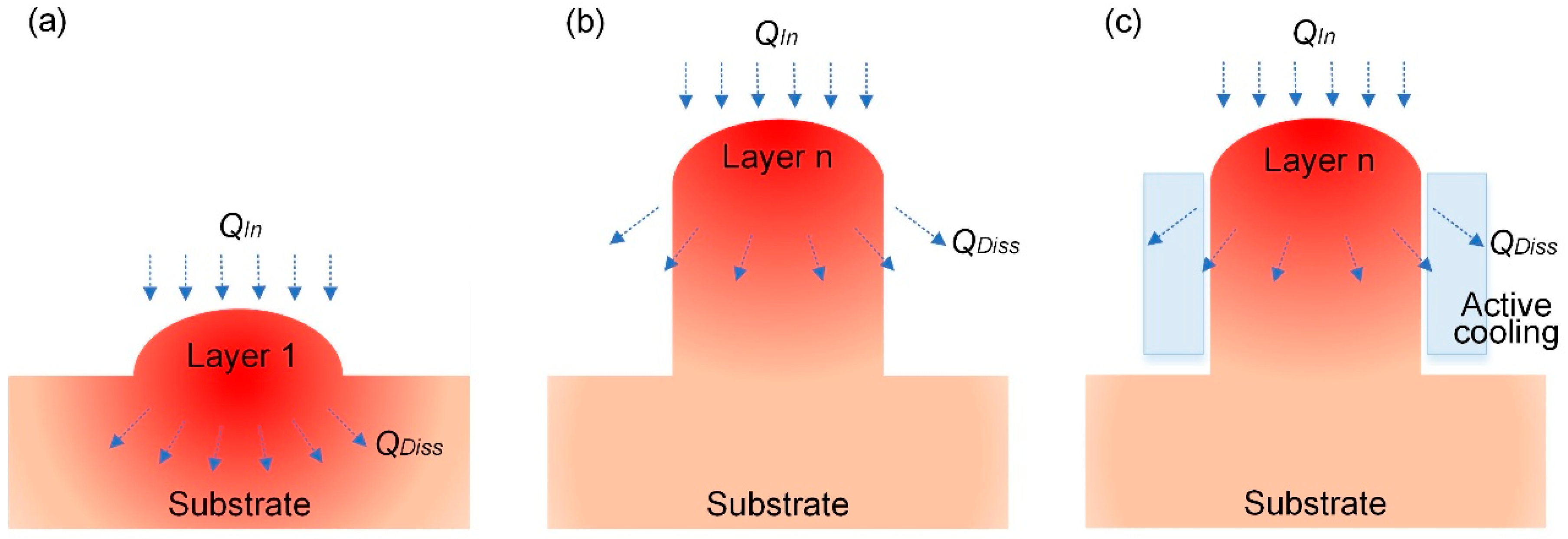
An alternative solution is to regulate the heat dissipation during WAAM, since variations in both heat input and heat dissipation may affect the solidification of the molten pool and, ultimately, the bead geometry. To control the heat dissipation as needed, an in-process active cooling system based on thermoelectric cooling technology is developed in this study. The relatively poor heat dissipation by means of convection and radiation is replaced with strong heat conduction (see Figure 1c), such that the heat dissipation of the upper layers could reach the same level as that of lower layers, thus eliminating their difference in bead geometry with no need for adjusting the process parameters. That is to say, the conflict between consistent bead geometry and high productivity can be resolved. The rest of this paper will introduce the in-process active cooling system and evaluate its efficacy in regulating the bead geometry during WAAM.
2. Materials and Methods
2.1. Experimental Setup
Figure 2a shows the experimental setup used in this study. It consisted of a robot (RTI2000, IGM, Wiener Neudorf, Austria) equipped with two power supplies (Synergic 5000, Fronius, Mississauga, ON, Canada) to implement WAAM based on Tandem GMAW. In Tandem GMAW, two welding wires that are placed in-line along the travel direction are fed through a single torch [20]. It has been demonstrated to be feasible for AM applications with the benefits of higher productivity than single-wire GMAW. The wire used was 2325 Al alloy (1.2 mm diameter), which was deposited onto a 2219 Al alloy substrate. Pure argon (99.99%) was used as the shielding gas with a constant flow rate of 22 L/min. In the experiments, a thermocouple of type K was located at a depth of 5 mm from the molten pool to record the thermal cycling, a high-speed camera (MotionPro Y4S1, IDT, Tallahassee, FL, United States) was used to capture the molten pool, and a laser scanning confocal microscope (LEXT OLS3100, Olympus, Tokyo, Japan) was used for microstructure analysis.
2.2. In-Process Active Cooling System
In order to regulate the heat dissipation of the upper layers during WAAM, it would be more effective if the cooling device was to be directly attached to the side surface instead of to the substrate. Cooling methods can be classified according to the medium used to transfer the heat. Commonly used methods include air cooling and liquid cooling. However, strong air flow near the molten pool is likely to disrupt the stability of the arc, whereas liquid cooling requires an additional liquid circulation system. Instead, this study adopted thermoelectric cooling technology [21] with the benefits of no circulating liquid, invulnerability to leak, small size, flexible shape, controllable cooling rate, and long life. A thermoelectric cooler operates by the Peltier effect, and is a solid-state active heat pump that transfers heat from one side of the device to the other with consumption of electrical energy. One side gets cooler while the other gets hotter [22]. As shown in Figure 2b, two thermoelectric coolers were distributed symmetrically on the two sides of the wall. The hot side of each cooler was attached to external fans such that it could remain at ambient temperature. The cold side was attached to the side surface of the wall to regulate the heat dissipation, separated by a highly thermally conductive silicone rubber whose function was to ensure good contact between the cooler and the side surface in the presence of the stair-stepping effect. The thickness of the silicone rubber is 2 mm. A step-motor-driven motion system was used to lift the active cooling system in the Z direction along with the increase of the wall height. The rated input voltage of the thermoelectric cooler is 12 V, the nominal cooling power is 180 W, and the maximum temperature difference between the two sides is 63 °C. Generally, the actual cooling power is a function of various factors including ambient temperature, heat sink performance, thermal load, Peltier module geometry, input voltage, etc. The input voltage can be easily adjusted so as to change the cooling power.
2.3. Experimental Design
A series of experiments were designed to investigate the respective effects of wall height, heat input, and heat dissipation on the bead geometry, as given in Table 1. These experiments were divided into three groups according to their heat dissipation conditions. Each experiment was repeated three times.
In Group I, the depositions were performed on a flat substrate with dimensions 150 mm (length) × 150 mm (width) × 6 mm (height) (just like Figure 1a). This could reflect the heat dissipation condition of lower layers. In Group II, the depositions were performed on an existing wall with dimensions 150 mm (length) × 12 mm (width) × 150 mm (height) (just like Figure 1b). The two side surfaces of the wall were exposed to the ambient air to reflect the heat dissipation condition of upper layers. In Group III, the depositions were also performed on an existing wall but the two side surfaces of the wall were attached to the thermoelectric coolers (just like Figure 1c). Groups III-1 and III-2 employed different cooling powers (nominal value) by adjusting the input voltage of the coolers. Within each group, three deposition experiments were conducted with different process parameters. Four main process parameters that affect the heat input, i.e., wire feed rate (WFR), travel speed (TS), arc voltage (U), and arc current (I), were considered. The selection of WFR covers a wide range. For lower WFR, the welding arc is not quite stable and incomplete melting occurs, while for higher WFR, pool overflowing occurs due to excessive heat input as well as the large arc force and strong droplet impingement. Note that the ratio of WFR to TS is fixed at 10 herein in order to maintain the same area of the bead cross section (i.e., the metal deposition rate per unit length) which is in direct proportion to WFR/TS [23]. It is difficult to compare different bead geometries if their cross-sectional areas are not the same. U and I were obtained from the power supplies once WFR and TS were determined.
From these experiments, we can analyze (1) the effect of heat input on the bead geometry by comparing the three experiments within each group; (2) the effect of wall height on the bead geometry by comparing Groups I and II; and (3) the effect of heat dissipation on the bead geometry by comparing Groups II and III.
3. Results and Discussion
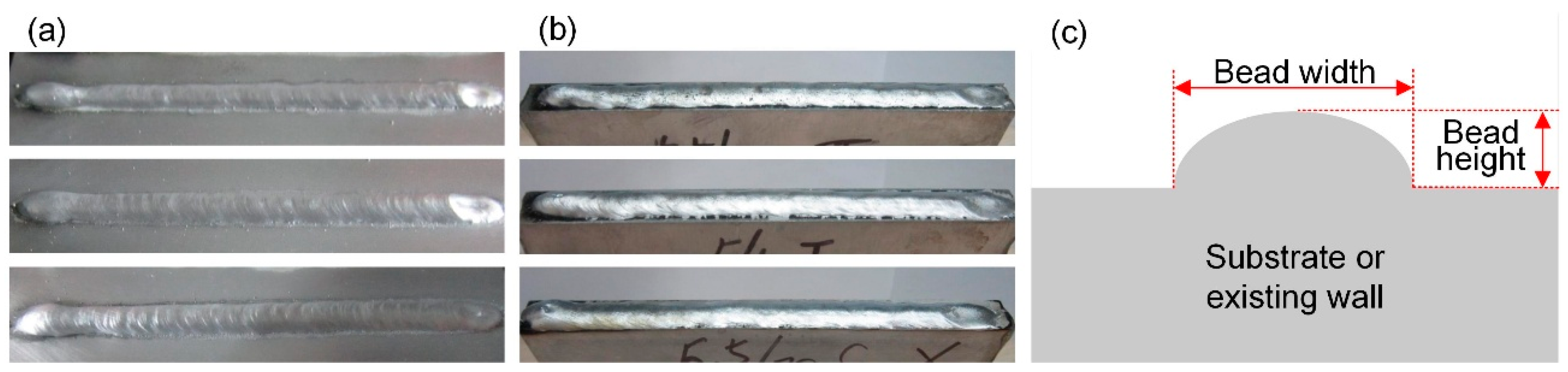
Figure 3a shows some of the deposited layers on the flat substrate, and Figure 3b shows some on the existing wall obtained in these experiments. They all have good bead appearance with little spatters and no visible defects. In the middle segment of each deposited layer, the bead width (W) and the bead height (H) were measured (see Figure 3c) with the aid of a laser displacement scanner (0.01 mm repeatable precision, HG-C1030, Panasonic, Suzhou, China), and then the ratio of width to height (RWTH) was calculated, as given in Table 2. The variation of the bead geometry can be indicated by RWTH since the cross-sectional area is a constant value. It can be seen that the three repeated experiments (Samples 1–3) show a maximum error of 0.74 mm in bead width and 0.23 mm in bead height. The discrepancy may be caused by the uncertainty of the molten pool solidification. Only the intermediate values (Sample 2) were recorded for the subsequent analysis.
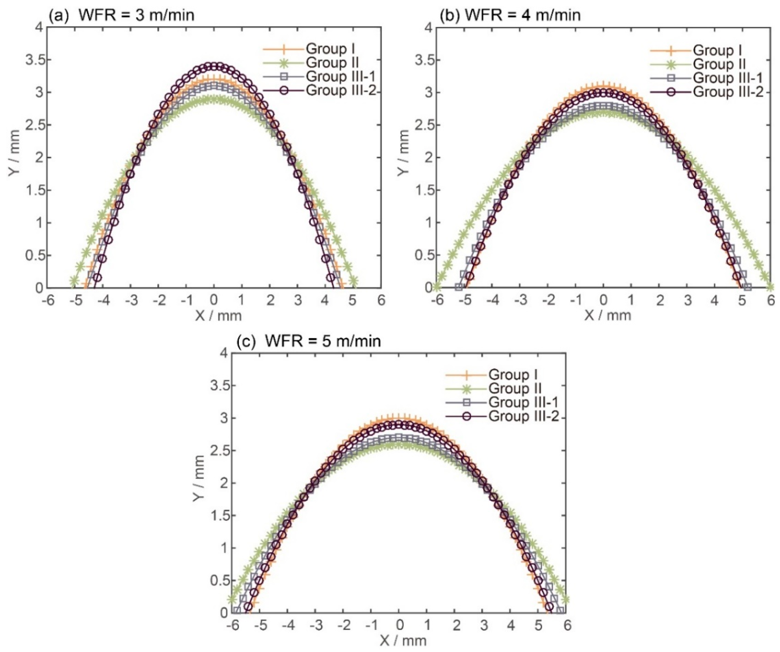
Figure 4 compares the bead width, bead height, and RWTH between different groups of experiments. Figure 5 compares the bead cross section profiles fitted based on a parabola model [24], which is expressed by
3.1. Effect of Heat Input on the Bead Geometry
From Figure 4, it is revealed that within each group of experiments, the bead width tends to be larger and the bead height tends to be smaller (i.e., RWTH is larger) as the WFR increases. To explain this, the heat input per unit length (QIn) is calculated as follows:
where η is the thermal efficiency, which is set to 0.7 in this study [25]. When the WFR is 3 m/min, 4 m/min, or 5 m/min, the corresponding heat input is about 4.65 × 10⁵ J/m (1630 W), 4.91 × 10⁵ J/m (2290 W), or 5.19 × 10⁵ J/m (3030 W), respectively. This clearly shows that the heat input is an increasing function of WFR. For smaller WFR, i.e., lower heat input, the molten pool does not have enough time to spread before solidification and, therefore, the RWTH tends to be smaller. For larger WFR, i.e., higher heat input, on the other hand, the viscosity of the material is reduced and the molten pool is much easier to spread [26], leading to larger RWTH. The above results prove that adjusting the heat input is one possible way to regulate the bead geometry during WAAM.
3.2. Effect of Wall Height on the Bead Geometry
By comparing the RWTH between Groups I and II in Figure 4, we can conclude that the upper layers (in Group II) obtain larger RWTH than the lower layers (in Group I) under the same process parameters. This is consistent with the above analysis that the heat dissipation condition becomes worse as the wall height increases, thereby slowing down the solidification of the molten pool. Besides this, their difference becomes more noticeable for larger WFR. This is because the higher the heat input is, the more difficult the heat dissipation through the upper layers becomes. This explains why it is a great challenge for WAAM to maintain consistent bead geometry from the bottom up. For example, if a 10.5 mm width wall is to be fabricated, the required WFR is about 5 m/min for lower layers according to Figure 4a. If this WFR remains the same regardless of the increase in the wall height, the obtained bead width is about 12.5 mm at upper layers. Only when the WFR is reduced to 3.2 m/min at upper layers can consistent bead geometry be achieved. Nevertheless, it should be noted that the deposition rate (DR) is also associated with the WFR as follows:
where ρ is the material density and d is the wire diameter. According to this equation, when the WFR is reduced from 5 m/min to 3.2 m/min, the corresponding deposition rate is also reduced from 30.5 g/min to 19.5 g/min, which greatly sacrifices productivity. Besides this, this adjustment relies on experience to a large extent and greatly complicates the build process.
3.3. Effect of Heat Dissipation on the Bead Geometry
The obtained RWTH in Group III-1, as shown in Figure 4c, is obviously decreased compared with that in Group II under the same process parameters, which clearly illustrates that thermoelectric cooling is more effective than convection and radiation in terms of absorbing heat from the molten pool. It is also noteworthy that when WFR = 3 m/min, the obtained RWTH at upper layers is very close to that at lower layers (in Group I), which implies that the difference in heat dissipation between upper and lower layers is well made up for by thermoelectric cooling. From Figure 5a, we can also see that the two profiles in Group I and Group III-1 tend to overlap. However, for larger WFR ranging from 4 to 5 m/min, the effect of thermoelectric cooling is less significant and the obtained RWTH is still larger than that at lower layers. This is because the cooling power is limited in this case, and a decreasing proportion of the heat is dissipated through the side surfaces with the increase of the heat input. Besides this, the large arc force and strong droplet impingement resulting from the large heat input also have great effect on the bead geometry, and could not be eliminated by thermoelectric cooling.
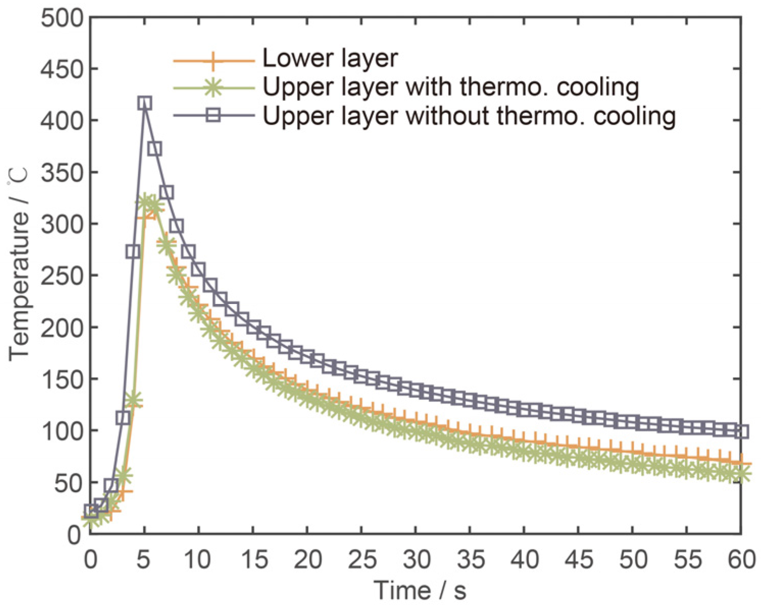
When the cooling power is increased to the maximum value in Group III-2, the obtained RWTH is further decreased as expected. In this case, the RWTH is much closer to that at lower layers when the WFR is 4 m/min, but still a little larger when the WFR is 5 m/min. If the cooling power is further increased, there is a great possibility to further decrease the RWTH to the same level as that at lower layers. To further validate the above results, the thermal cycling and the molten pool shapes of lower and upper layers are also compared (when WFR = 4 m/min), as displayed in Figure 6 and Figure 7, respectively. The peak temperature is 313 °C at the lower layer and is 320 °C at the upper layer with thermoelectric cooling, as seen in Figure 6. The small discrepancy (7 °C) may reflect that their heat dissipation conditions are quite similar. If there is no thermoelectric cooling, however, this discrepancy is about 102 °C.
The molten pool tails at the lower layer and at the upper layer with thermoelectric cooling are also quite similar—like a cone—as seen in Figure 7a,b, respectively. However, the molten pool flows randomly with intensive metallurgical reaction if there is no thermoelectric cooling, which makes it difficult to detect the pool tail as seen in Figure 7c. This further proves that the lower and the upper layers could experience a similar heat dissipation condition with the aid of thermoelectric cooling.
From the above results, we can conclude that once the cooling power matches the heat input, the difference in heat dissipation between the upper and lower layers can be eliminated, which contributes to achieving consistent bead geometry from the bottom up with no need to adjust the process parameters, i.e., without sacrificing the deposition rate. When the heat input is 1630 W or 2290 W, the required cooling power is 240 W or 360 W, respectively, which accounts for 14.8% or 15.7% of the corresponding heat input. If this ratio is smaller, the RWTH tends to be larger than that expected; but if larger, the RWTH tends to be smaller. This shows that the ratio of cooling power to heat input should be maintained basically constant. It should be pointed out that more accurate adjustment of the cooling power needs further research with regard to thermal modeling of the WAAM process.
3.4. Case Study
Two ten-layer deposition cases were compared under the same process parameters: WFR = 4 m/min and TS = 0.4 m/min. One has the same heat dissipation condition as that in Group III-2 and the other as that in Group II. In the experiments, the interlayer temperature was retained at room temperature to avoid its effect on the bead geometry [15]. Figure 8 shows that the effective bead width and the total wall height are 9.9 mm and 26.8 mm, respectively, with thermoelectric cooling, compared to 12.4 mm and 21.6 mm without thermoelectric cooling. The bead tends to be narrower and taller when the thermoelectric cooling is employed, which is particularly beneficial for the fabrication of thin-walled structures in terms of geometric accuracy and productivity. For example, for when the dimensions of the final part are 100 mm (length) × 8 mm (width) × 100 mm (height), the comparison between the two test cases are given in Table 3. When thermoelectric cooling is employed, the bead width error is reduced by 56.8% and the material utilization is increased by 16.3% because a smaller amount of material needs to be removed through post-processing. On the other hand, the total fabrication time (including both deposition time and cooling time) is reduced significantly by 60.9%. One reason is that the ratio of bead height to bead width is increased and, therefore, the required number of layers is smaller, which means the deposition time is reduced (19.6%). The other reason is that the cooling rate is increased (see Figure 6) and, therefore, the cooling time is reduced (64.4%). It should be noted that without external cooling, the cooling time accounts for the majority of the total time.
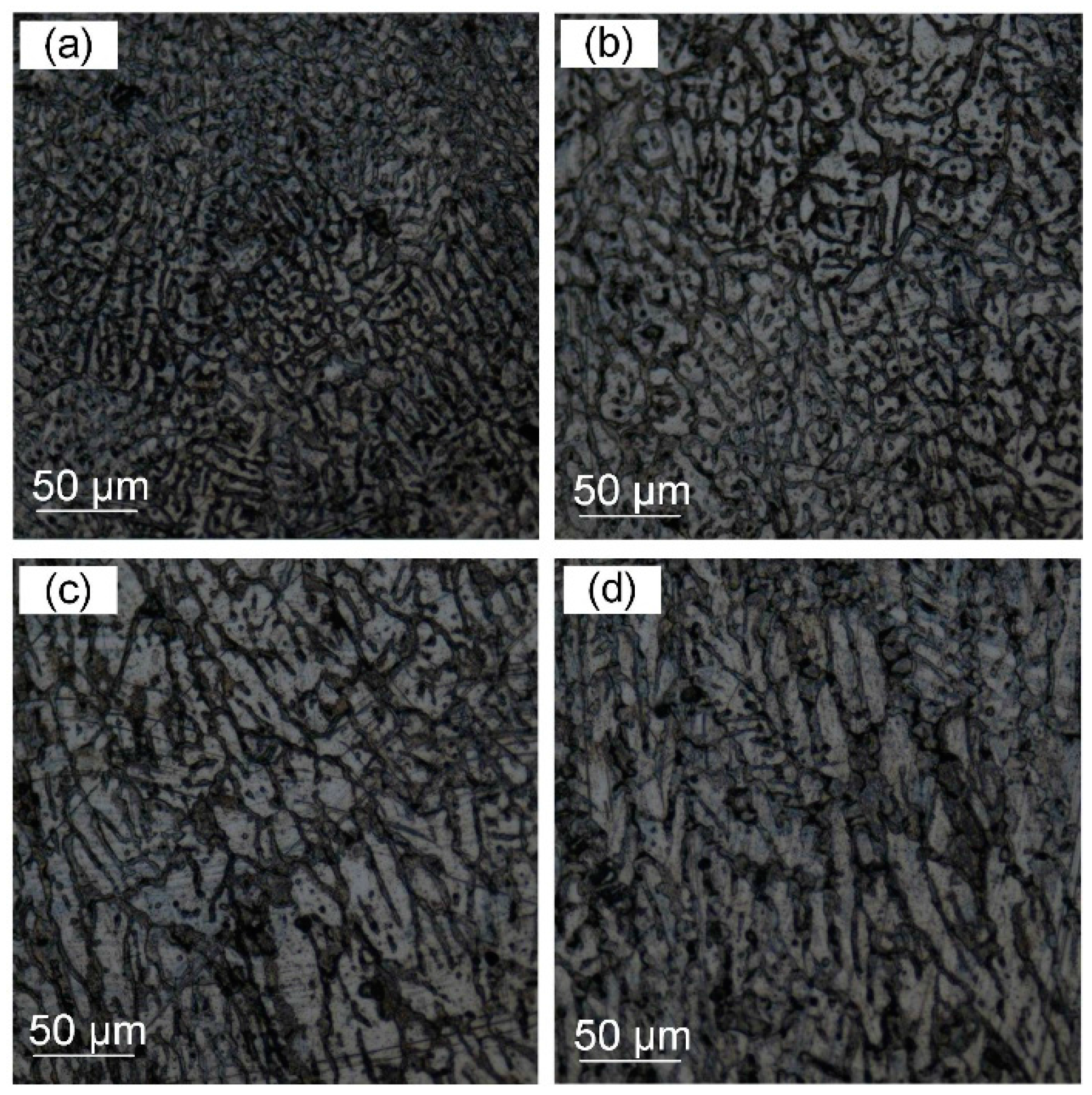
The effect of thermoelectric cooling on microstructures was also analyzed. Specimens were taken from both the middle and the bottom parts of the two walls. As shown in Figure 9a,b, the microstructures in the middle parts are characterized by dendrite grains. The average grain size is 5.97 μm with thermoelectric cooling, which is much finer than that without thermoelectric cooling (7.96 μm). This is because the former undergoes a much higher cooling rate that helps to refine the grain size by increasing the number of particles that nucleate grains and by affecting the development of constitutional undercooling [27]. The microstructures in the bottom parts, as shown in Figure 9c,d, are mainly slender columnar grains perpendicular to the substrate as the direction of the grain growth is mainly along the largest temperature gradient [28]. Their difference is not obvious.
4. Conclusions
The varying heat dissipation is one of the main constraints of WAAM, degrading geometric accuracy and limiting productivity. Both reducing the heat input via adjusting the process parameters and enhancing the heat dissipation via thermoelectric cooling have the potential to overcome this obstacle. However, the latter exhibits great superiorities as demonstrated in this study. The following conclusions can be drawn from the present study:
- (1)
- The upper and the lower layers could experience a similar heat dissipation condition with the aid of thermoelectric cooling, therefore resulting in similar thermal cycling, molten pool shape, and, ultimately, bead geometry with no need to adjust the process parameters. The case study shows a decrease of 56.8% in bead width error and an increase of 16.3% in material utilization.
- (2)
- The productivity of the WAAM process can be significantly improved with thermoelectric cooling, due to not only the increased ratio of bead height to bead width, but also the reduced interlayer dwell time. The case study shows a decrease of 60.9% in total fabrication time.
- (3)
- Much finer microstructures can be obtained in the middle parts of the deposited walls, and are attributed to the increased cooling rate. The average grain size is reduced from 7.96 μm to 5.97 μm.
In conclusion, the technique offers an innovative way to regulate bead geometry during WAAM, significantly improving its capability in fabricating thin-walled structures in terms of geometric accuracy, productivity, and microstructure. This method can also be extended to other layered manufacturing processes. Future work will focus on the thermal modeling of the WAAM process for accurate adjustment of the cooling power, and improvement of the active cooling system such that it could be fitted to parts with more complex shapes.
Acknowledgments
This paper was supported by the National Natural Science Foundation of China (No. 51475009), China Postdoctoral Science Foundation (No. 2017M610726) and Postdoctoral Research Foundation of Chaoyang District (No. 2017ZZ-01-09).
Author Contributions
Fang Li developed the experimental setup and wrote the manuscript; Shujun Chen designed the experiments; Junbiao Shi and Yun Zhao performed the experiments; Hongyu Tian analyzed the data.
Conflicts of Interest
The authors declare no conflict of interest.
References
- Thompson, M.K.; Moroni, G.; Vaneker, T.; Fadel, G.; Campbell, R.I.; Gibson, I.; Bernard, A.; Schulz, J.; Graf, P.; Ahuja, B.; et al. Design for additive manufacturing: Trends, opportunities, considerations, and constraints. CIRP Ann. Manuf. Technol. 2016, 65, 737–760. [Google Scholar] [CrossRef] [Green Version]
- Saboori, A.; Gallo, D.; Biamino, S.; Fino, P.; Lombardi, M. An overview of additive manufacturing of titanium components by directed energy deposition: Microstructure and mechanical properties. Appl. Sci. 2017, 7, 883. [Google Scholar] [CrossRef]
- Gao, W.; Zhang, Y.; Ramanujan, D.; Ramani, K.; Chen, Y.; Williams, C.B.; Wang, C.C.L.; Shin, Y.C.; Zhang, S.; Zavattieri, P.D. The status, challenges, and future of additive manufacturing in engineering. Comput. Aided Des. 2015, 69, 65–89. [Google Scholar] [CrossRef]
- Frazier, W.E. Metal Additive Manufacturing: A Review. J. Mater. Eng. Perform. 2014, 23, 1917–1928. [Google Scholar] [CrossRef]
- Zhong, Y.; Rännar, L.E.; Wikman, S.; Koptyug, A.; Liu, L.; Cui, D.; Shen, Z. Additive manufacturing of ITER first wall panel parts by two approaches: Selective laser melting and electron beam melting. Fusion Eng. Des. 2017, 116, 24–33. [Google Scholar] [CrossRef]
- Ding, D.; Pan, Z.; Cuiuri, D.; Li, H. Wire-feed additive manufacturing of metal components: Technologies, developments and future interests. Int. J. Adv. Manuf. Technol. 2015, 81, 465–481. [Google Scholar] [CrossRef]
- Pan, Z.; Ding, D.; Wu, B.; Cuiuri, D.; Li, H.; Norrish, J. Arc Welding Processes for Additive Manufacturing: A Review. In Transactions on Intelligent Welding Manufacturing; Chen, S., Zhang, Y., Feng, Z., Eds.; Springer: Singapore, 2017; Volume 1, pp. 3–24. ISBN 978-981-10-5355-9. [Google Scholar]
- Xu, X.; Ding, J.; Ganguly, S.; Diao, C.; Williams, S. Oxide accumulation effects on wire + arc layer-by-layer additive manufacture process. J. Mater. Process. Technol. 2017, 252, 739–750. [Google Scholar] [CrossRef]
- Ding, D.; Pan, Z.; Cuiuri, D.; Li, H. A tool-path generation strategy for wire and arc additive manufacturing. Int. J. Adv. Manuf. Technol. 2014, 73, 173–183. [Google Scholar] [CrossRef]
- Williams, S.W.; Martina, F.; Addison, A.C.; Ding, J.; Pardal, G.; Colegrove, P. Wire + arc additive manufacturing. Mater. Sci. Technol. 2016, 7, 641–647. [Google Scholar] [CrossRef]
- Ding, D.; Pan, Z.; Cuiuri, D.; Li, H. A practical path planning methodology for wire and arc additive manufacturing of thin-walled structures. Robot. Comput. Integr. Manuf. 2015, 34, 8–19. [Google Scholar] [CrossRef]
- Li, F.; Chen, S.; Shi, J.; Tian, H.; Zhao, Y. Evaluation and optimization of a hybrid manufacturing process combining wire arc additive manufacturing with milling for the fabrication of stiffened panels. Appl. Sci. 2017, 7, 1233. [Google Scholar] [CrossRef]
- Michaleris, P. Modeling metal deposition in heat transfer analyses of additive manufacturing processes. Finite Elem. Anal. Des. 2014, 86, 51–60. [Google Scholar] [CrossRef]
- Zhao, H.; Zhang, G.; Yin, Z.; Wu, L. A 3D dynamic analysis of thermal behavior during single-pass multi-layer weld-based rapid prototyping. J. Mater. Process. Technol. 2011, 211, 488–495. [Google Scholar] [CrossRef]
- Wu, B.; Ding, D.; Pan, Z.; Cuiuri, D.; Li, H.; Han, J.; Fei, Z. Effects of heat accumulation on the arc characteristics and metal transfer behavior in wire arc additive manufacturing of Ti6Al4V. J. Mater. Process. Technol. 2017, 250, 304–312. [Google Scholar] [CrossRef]
- Xiong, J.; Zhang, G.; Hu, J.; Wu, L. Bead geometry prediction for robotic GMAW-based rapid manufacturing through a neural network and a second-order regression analysis. J. Intell. Manuf. 2014, 25, 157–163. [Google Scholar] [CrossRef]
- Wang, H.; Jiang, W.; Ouyang, J.; Kovacevic, R. Rapid prototyping of 4043 al-alloy parts by VP-GTAW. J. Mater. Process. Technol. 2004, 148, 93–102. [Google Scholar] [CrossRef]
- Geng, H.; Li, J.; Xiong, J.; Lin, X. Optimisation of interpass temperature and heat input for wire and arc additive manufacturing 5A06 aluminium alloy. Sci. Technol. Weld. Join. 2017, 22, 472–483. [Google Scholar] [CrossRef]
- Xiong, J.; Yin, Z.; Zhang, W. Closed-loop control of variable layer width for thin-walled parts in wire and arc additive manufacturing. J. Mater. Process. Technol. 2016, 233, 100–106. [Google Scholar] [CrossRef]
- Sproesser, G.; Chang, Y.J.; Pittner, A.; Finkbeiner, M.; Rethmeier, M. Environmental energy efficiency of single wire and tandem gas metal arc welding. Weld. World 2017, 61, 733–743. [Google Scholar] [CrossRef]
- Zhao, D.; Tan, G. A review of thermoelectric cooling: Materials, modeling and applications. Appl. Therm. Eng. 2014, 66, 15–24. [Google Scholar] [CrossRef]
- Meng, J.H.; Wang, X.D.; Zhang, X.X. Transient modeling and dynamic characteristics of thermoelectric cooler. Appl. Energy 2013, 108, 340–348. [Google Scholar] [CrossRef]
- Ding, D.; Pan, Z.; Cuiuri, D.; Li, H.; Duin, S.V.; Larkin, N. Bead modelling and implementation of adaptive MAT path in wire and arc additive manufacturing. Robot. Comput. Integr. Manuf. 2016, 39, 32–42. [Google Scholar] [CrossRef]
- Xiong, J.; Zhang, G.; Gao, H.; Wu, L. Modeling of bead section profile and overlapping beads with experimental validation for robotic GMAW-based rapid manufacturing. Robot. Comput. Integr. Manuf. 2013, 29, 417–423. [Google Scholar] [CrossRef]
- Xiong, J.; Zhang, G.; Zhang, W. Forming appearance analysis in multi-layer single-pass GMAW-based additive manufacturing. Int. J. Adv. Manuf. Technol. 2015, 80, 1767–1776. [Google Scholar] [CrossRef]
- Nikam, S.H.; Jain, N.K.; Jhavar, S. Thermal modeling of geometry of single-track deposition in micro-plasma transferred arc deposition process. J. Mater. Process. Technol. 2016, 230, 121–130. [Google Scholar] [CrossRef]
- Easton, M.A.; Stjohn, D.H. Improved prediction of the grain size of aluminum alloys that includes the effect of cooling rate. Mater. Sci. Eng. A 2008, 486, 8–13. [Google Scholar] [CrossRef]
- Cong, B.; Qi, Z.; Qi, B.; Sun, H.; Zhao, G.; Ding, J. A comparative study of additively manufactured thin wall and block structure with Al-6.3%Cu alloy using cold metal transfer process. Appl. Sci. 2017, 7, 275. [Google Scholar] [CrossRef]
Figure 1.
Schematic diagram of heat input (QIn) and heat dissipation (QDiss) during (a) welding; (b) wire and arc-based additive manufacturing (WAAM); (c) WAAM with active cooling.
Figure 1.
Schematic diagram of heat input (QIn) and heat dissipation (QDiss) during (a) welding; (b) wire and arc-based additive manufacturing (WAAM); (c) WAAM with active cooling.

Figure 2.
Experimental setup: (a) Robot system for WAAM; (b) Enlarged view of the active cooling system.
Figure 2.
Experimental setup: (a) Robot system for WAAM; (b) Enlarged view of the active cooling system.
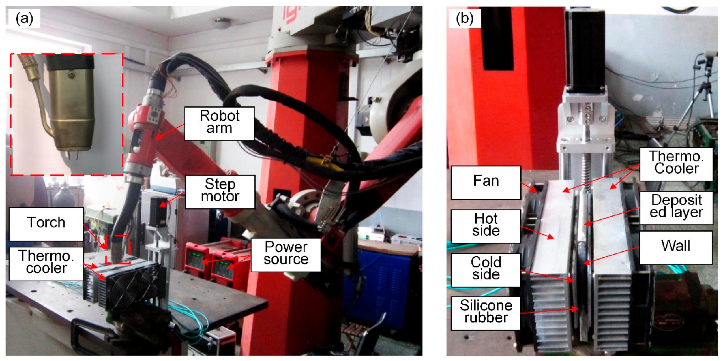
Figure 3.
(a) Deposited layers on the flat substrate; (b) Deposited layers on the existing wall; (c) Schematic diagram of bead width and bead height.
Figure 3.
(a) Deposited layers on the flat substrate; (b) Deposited layers on the existing wall; (c) Schematic diagram of bead width and bead height.

Figure 4.
(a) Relation between bead width and wire feed rate (WFR) in Groups I–III; (b) Relation between bead height and WFR in Groups I–III; (c) Relation between ratio of width to height (RWTH) and WFR in Groups I–III.
Figure 4.
(a) Relation between bead width and wire feed rate (WFR) in Groups I–III; (b) Relation between bead height and WFR in Groups I–III; (c) Relation between ratio of width to height (RWTH) and WFR in Groups I–III.
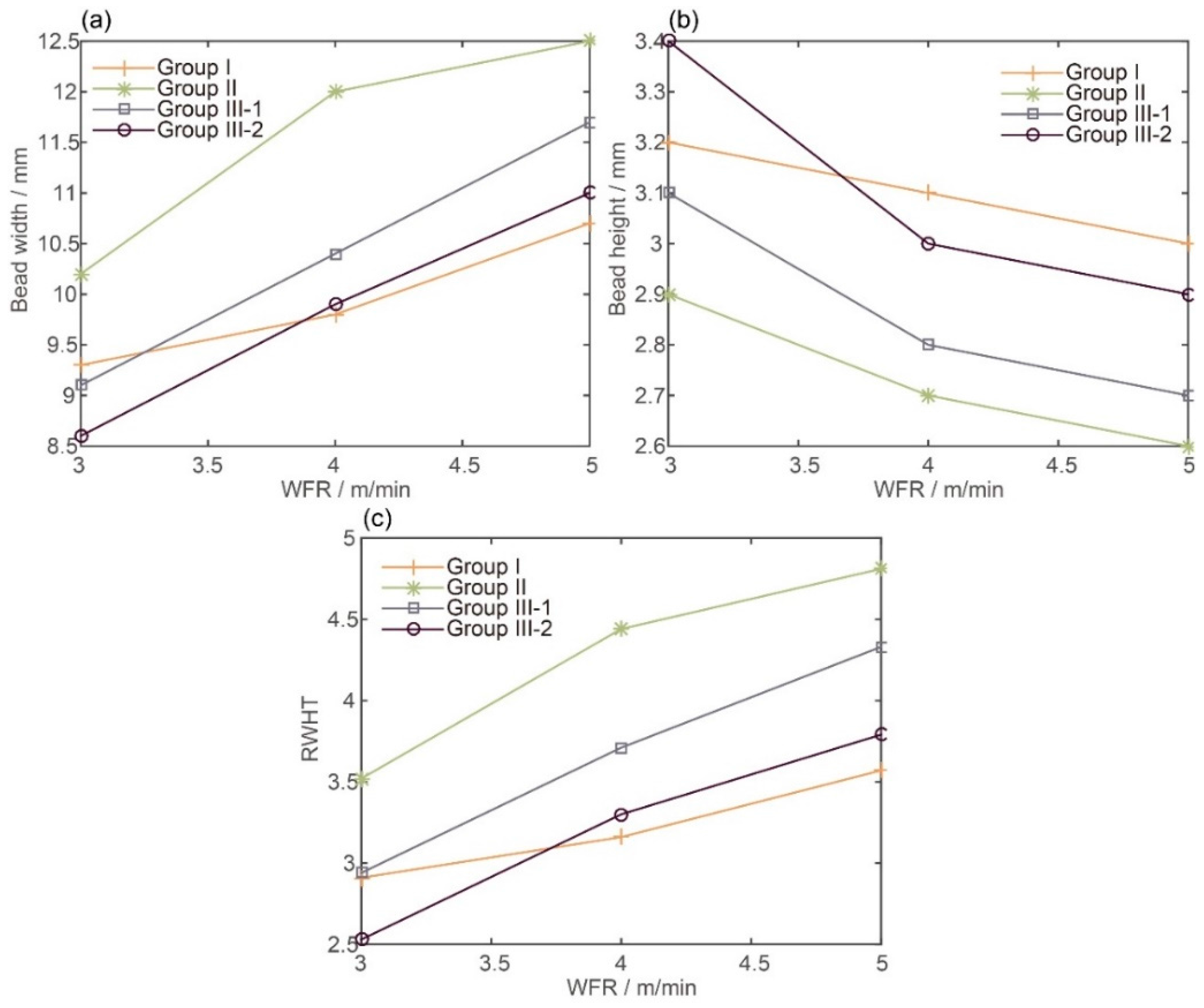
Figure 5.
Bead cross section profile comparison between Groups I–III (a) when WFR = 3 m/min; (b) when WFR = 4 m/min; (c) when WFR = 5 m/min.
Figure 5.
Bead cross section profile comparison between Groups I–III (a) when WFR = 3 m/min; (b) when WFR = 4 m/min; (c) when WFR = 5 m/min.

Figure 6.
Thermal cycling comparison (when WFR = 4 m/min).

Figure 7.
Molten pool shape comparison (when WFR = 4 m/min): (a) at the lower layer; (b) at the upper layer with thermoelectric cooling; (c) at the upper layer without thermoelectric cooling.
Figure 7.
Molten pool shape comparison (when WFR = 4 m/min): (a) at the lower layer; (b) at the upper layer with thermoelectric cooling; (c) at the upper layer without thermoelectric cooling.
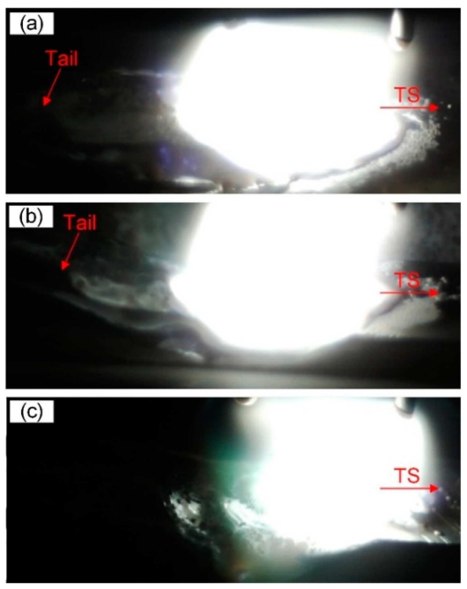
Figure 8.
Cross section of two ten-layer walls (a) with thermoelectric cooling; (b) without thermoelectric cooling.
Figure 8.
Cross section of two ten-layer walls (a) with thermoelectric cooling; (b) without thermoelectric cooling.
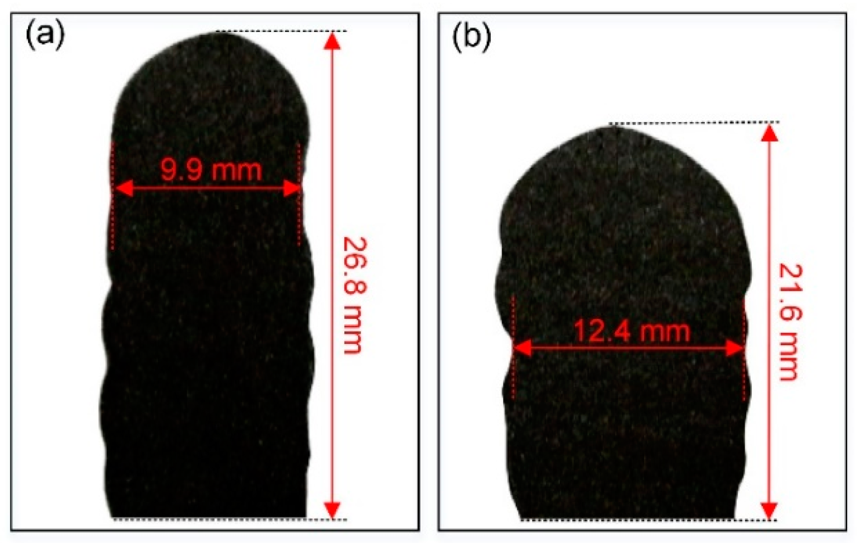
Figure 9.
Microstructures in the middle parts of the deposited layers (a) with thermoelectric cooling; (b) without thermoelectric cooling. Microstructures in the bottom parts of the deposited layers (c) with thermoelectric cooling; (d) without thermoelectric cooling.
Figure 9.
Microstructures in the middle parts of the deposited layers (a) with thermoelectric cooling; (b) without thermoelectric cooling. Microstructures in the bottom parts of the deposited layers (c) with thermoelectric cooling; (d) without thermoelectric cooling.

Table 1.
Heat dissipation conditions and parameter sets in the experiments.
| Run No. | Group No. | Heat Dissipation Conditions | Process Parameters | ||||
|---|---|---|---|---|---|---|---|
| WFR (m/min) | TS (m/min) | U (V) | I (A) | Cooling Power | |||
| 1 | I | Flat substrate + conduction | 3 | 0.3 | 130 | 17.9 | - |
| 2 | 4 | 0.4 | 176 | 18.6 | - | ||
| 3 | 5 | 0.5 | 222 | 19.5 | - | ||
| 4 | II | Wall + convection & radiation | 3 | 0.3 | 130 | 17.9 | - |
| 5 | 4 | 0.4 | 176 | 18.6 | - | ||
| 6 | 5 | 0.5 | 222 | 19.5 | - | ||
| 7 | III-1 | Wall + thermoelectric cooling | 3 | 0.3 | 130 | 17.9 | 240 W |
| 8 | 4 | 0.4 | 176 | 18.6 | 240 W | ||
| 9 | 5 | 0.5 | 222 | 19.5 | 240 W | ||
| 10 | III-2 | 3 | 0.3 | 130 | 17.9 | 360 W | |
| 11 | 4 | 0.4 | 176 | 18.6 | 360 W | ||
| 12 | 5 | 0.5 | 222 | 19.5 | 360 W | ||
Table 2.
Measurement data.
| Run No. | Sample 1 | Sample 2 | Sample 3 | Maximum Error | ||||
|---|---|---|---|---|---|---|---|---|
| Width (mm) | Height (mm) | Width (mm) | Height (mm) | Width (mm) | Height (mm) | Width (mm) | Height (mm) | |
| 1 | 9.27 | 3.27 | 9.34 | 3.23 | 9.48 | 3.16 | 0.21 | 0.11 |
| 2 | 9.66 | 3.18 | 9.83 | 3.11 | 10.01 | 3.03 | 0.35 | 0.15 |
| 3 | 10.55 | 3.09 | 10.71 | 3.02 | 10.95 | 2.91 | 0.40 | 0.18 |
| 4 | 10.11 | 2.97 | 10.22 | 2.94 | 10.36 | 2.89 | 0.25 | 0.08 |
| 5 | 11.85 | 2.79 | 12.04 | 2.74 | 12.33 | 2.59 | 0.48 | 0.20 |
| 6 | 12.44 | 2.66 | 12.52 | 2.63 | 12.66 | 2.57 | 0.22 | 0.09 |
| 7 | 9.01 | 3.17 | 9.15 | 3.13 | 9.54 | 3.03 | 0.53 | 0.14 |
| 8 | 10.32 | 2.88 | 10.43 | 2.85 | 10.67 | 2.71 | 0.35 | 0.17 |
| 9 | 11.57 | 2.77 | 11.74 | 2.74 | 12.21 | 2.66 | 0.64 | 0.11 |
| 10 | 8.49 | 3.45 | 8.63 | 3.42 | 8.96 | 3.31 | 0.47 | 0.14 |
| 11 | 9.86 | 3.05 | 9.96 | 3.01 | 10.35 | 2.90 | 0.49 | 0.15 |
| 12 | 10.80 | 2.96 | 11.02 | 2.91 | 11.54 | 2.73 | 0.74 | 0.23 |
Table 3.
Comparison between the two test cases.
| Indicator | Convection + Radiation | Thermoelectric Cooling | Relative Error |
|---|---|---|---|
| Bead width error | 4.4 mm | 1.9 mm | −56.8% |
| Material utilization | 64.5% | 80.8% | +16.3% |
| Number of layers | 46 | 37 | −19.6% |
| Deposition time | 690 s | 555 s | −19.6% |
| Cooling time | 8100 s | 2880 s | −64.4% |
| Total time | 8790 s | 3435 s | −60.9% |
© 2018 by the authors. Licensee MDPI, Basel, Switzerland. This article is an open access article distributed under the terms and conditions of the Creative Commons Attribution (CC BY) license (http://creativecommons.org/licenses/by/4.0/).
Share and Cite
MDPI and ACS Style
Li, F.; Chen, S.; Shi, J.; Zhao, Y.; Tian, H. Thermoelectric Cooling-Aided Bead Geometry Regulation in Wire and Arc-Based Additive Manufacturing of Thin-Walled Structures. Appl. Sci. 2018, 8, 207. https://doi.org/10.3390/app8020207
AMA Style
Li F, Chen S, Shi J, Zhao Y, Tian H. Thermoelectric Cooling-Aided Bead Geometry Regulation in Wire and Arc-Based Additive Manufacturing of Thin-Walled Structures. Applied Sciences. 2018; 8(2):207. https://doi.org/10.3390/app8020207
Chicago/Turabian StyleLi, Fang, Shujun Chen, Junbiao Shi, Yun Zhao, and Hongyu Tian. 2018. "Thermoelectric Cooling-Aided Bead Geometry Regulation in Wire and Arc-Based Additive Manufacturing of Thin-Walled Structures" Applied Sciences 8, no. 2: 207. https://doi.org/10.3390/app8020207
Note that from the first issue of 2016, this journal uses article numbers instead of page numbers. See further details here.