Evaluation and Optimization of a Hybrid Manufacturing Process Combining Wire Arc Additive Manufacturing with Milling for the Fabrication of Stiffened Panels


Abstract
:Featured Application
Abstract
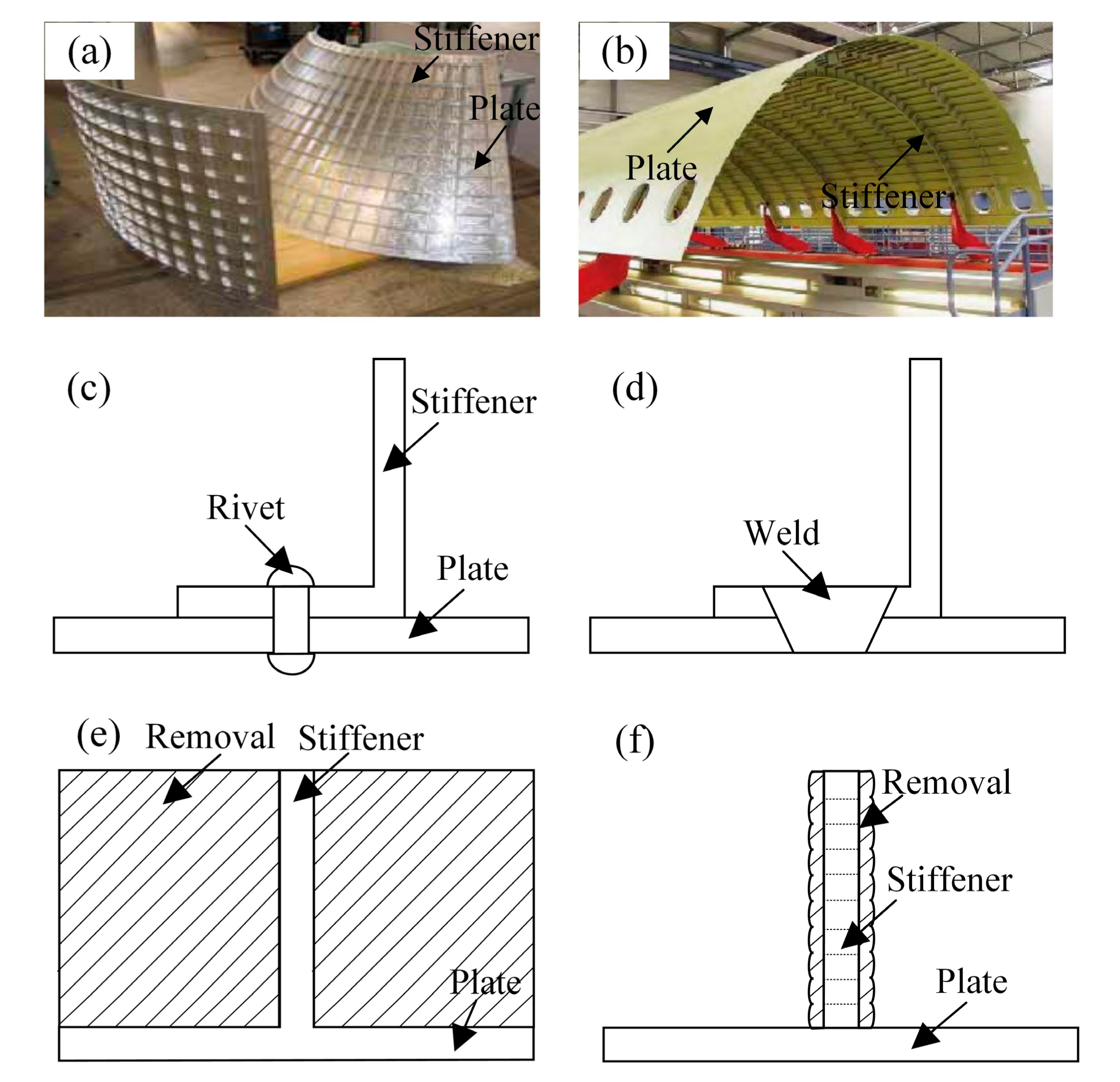
1. Introduction
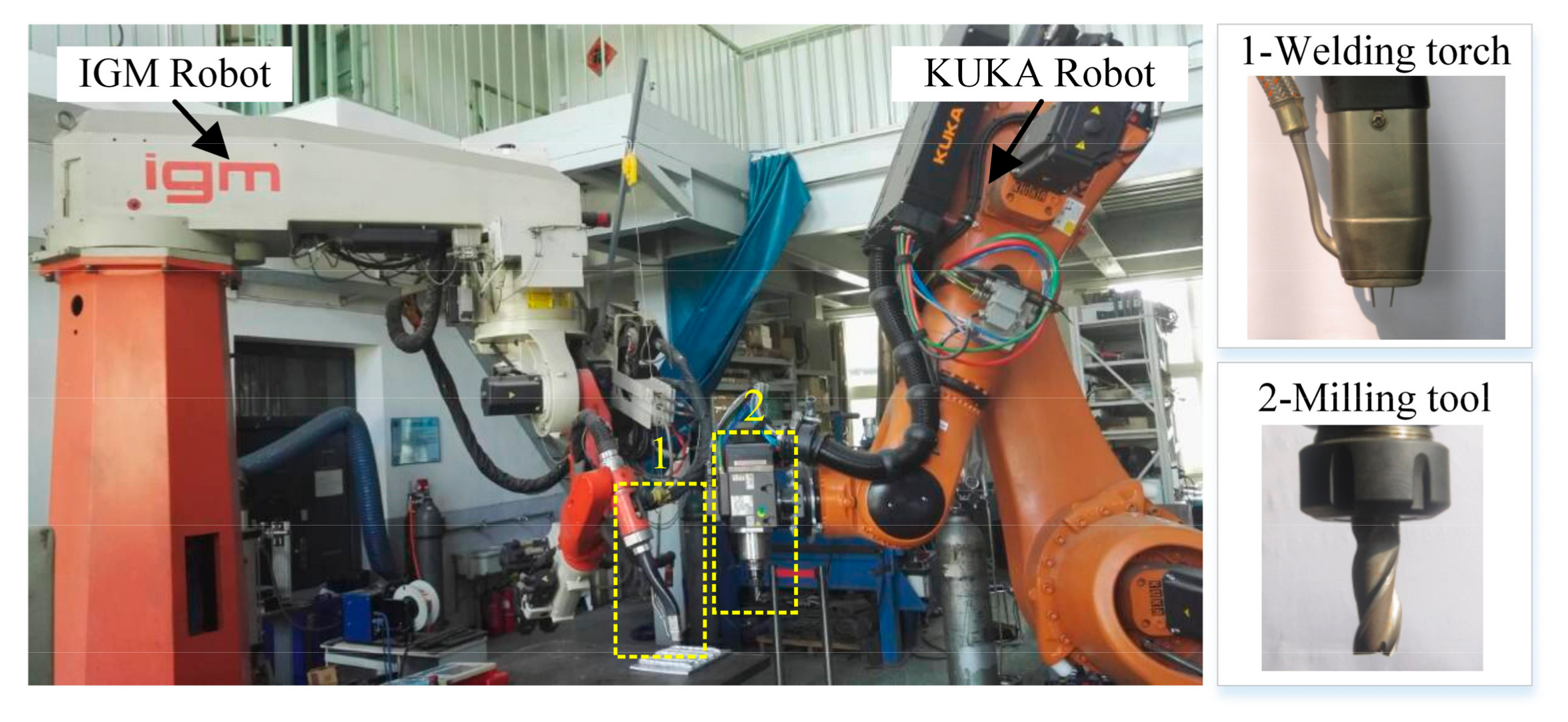
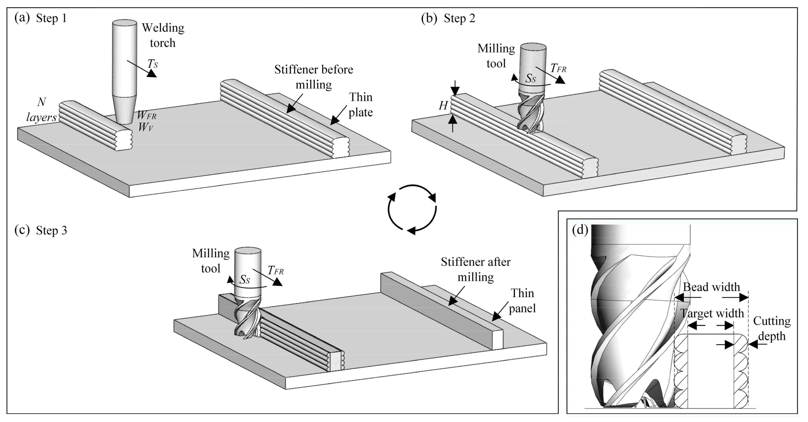
2. System Description
3. Evaluation of Surface Quality, Material Utilization, and Efficiency
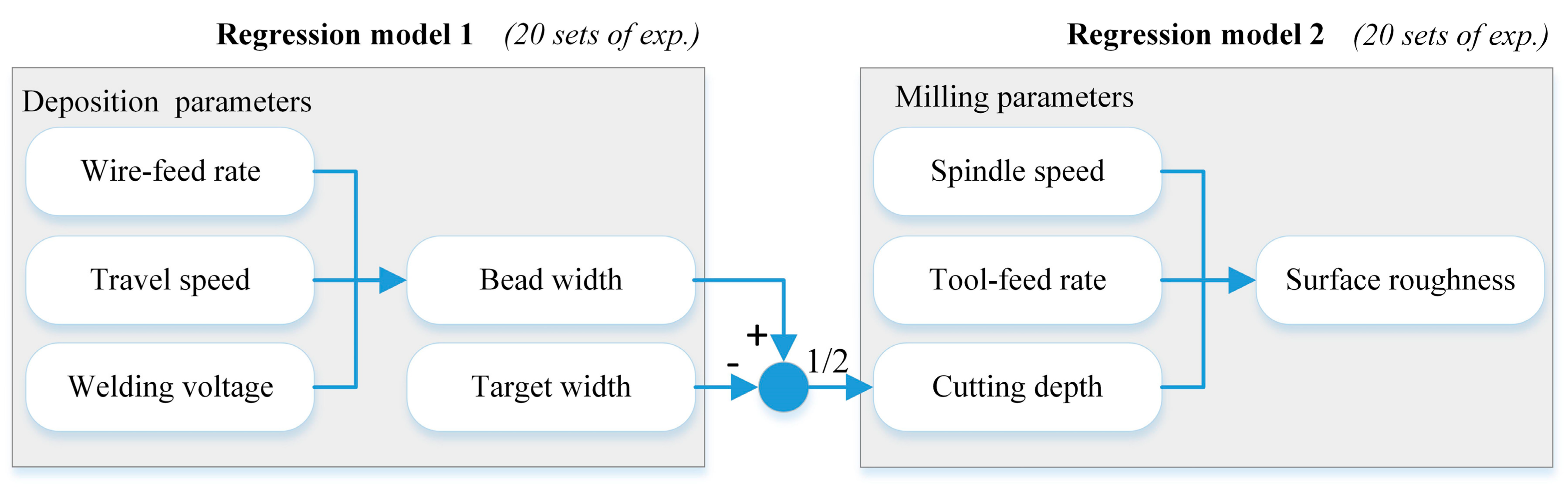
3.1. Evaluation of Surface Quality
3.1.1. Identifying Predominant Factors Affecting the Response and Determining Their Limits
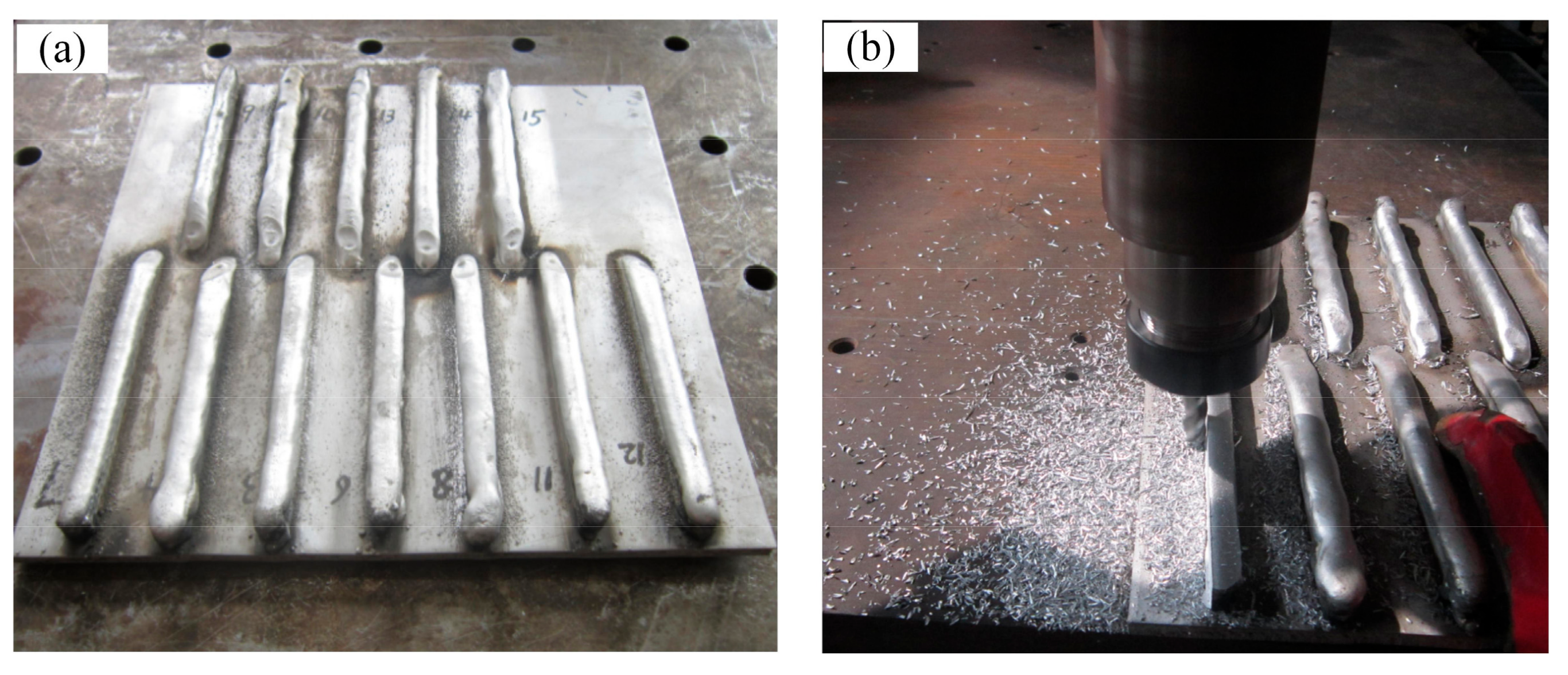
3.1.2. Generating Experimental Design Matrix and Conducting the Experiments
3.1.3. Developing and Validating the Regression Models
3.1.4. Developing Surface Roughness Model
3.2. Evaluation of Material Utilization
3.3. Evaluation of Efficiency
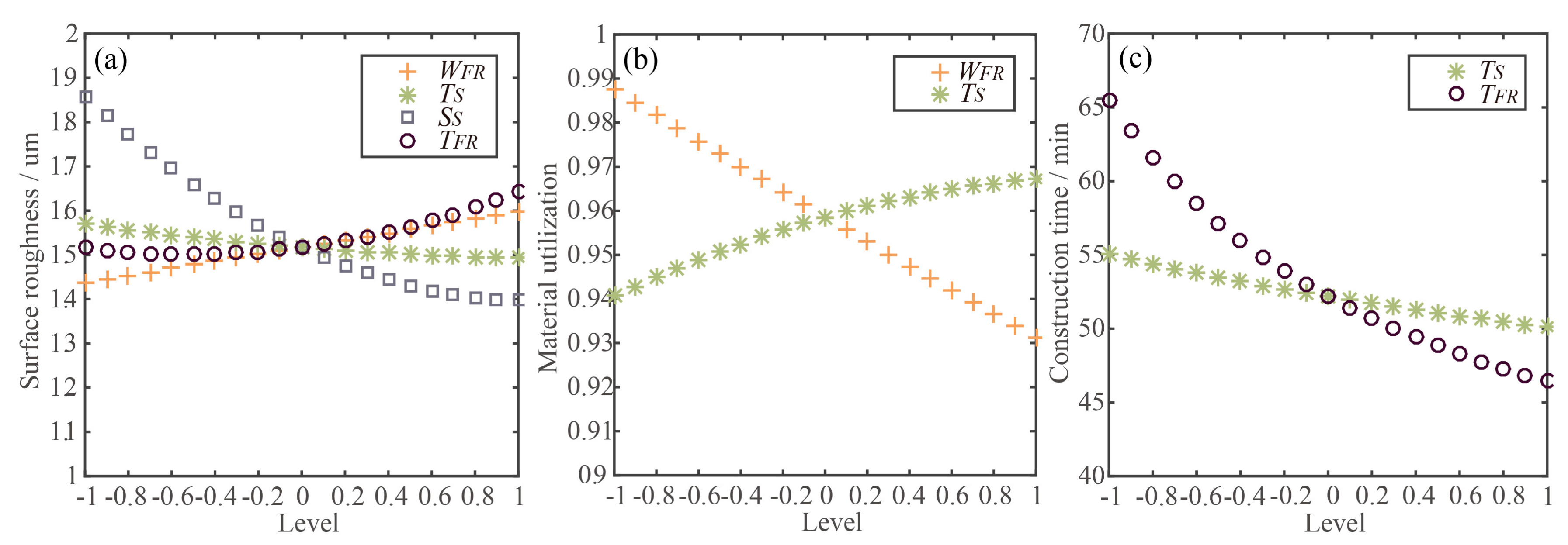
3.4. Effects of Process Parameters on the Performances
4. Parameter Optimization
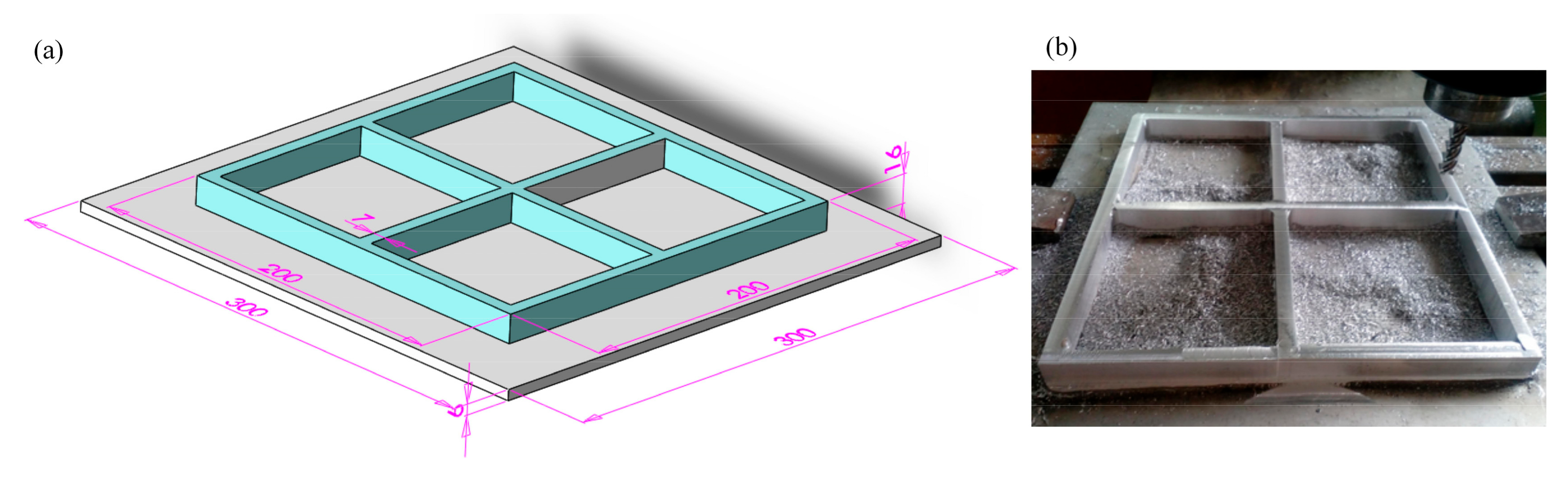
5. Case Study
6. Conclusions and Future Work
Acknowledgments
Author Contributions
Conflicts of Interest
References
- Gao, W.; Zhang, Y.; Ramanujan, D.; Ramani, K.; Williams, C.B. The status, challenges, and future of additive manufacturing in engineering. Comput. Aided Des. 2015, 69, 65–89. [Google Scholar] [CrossRef]
- Singh, S.; Ramakrishna, S.; Singh, R. Material issues in additive manufacturing: A review. J. Manuf. Process. 2017, 25, 185–200. [Google Scholar] [CrossRef]
- Frazier, W.E. Metal Additive Manufacturing: A Review. J. Mater. Eng. Perform. 2014, 23, 1917–1928. [Google Scholar] [CrossRef]
- Ding, D.; Pan, Z.; Cuiuri, D.; Li, H. Wire-feed additive manufacturing of metal components: Technologies, developments and future interests. Int. J. Adv. Manuf. Technol. 2015, 81, 465–481. [Google Scholar] [CrossRef]
- Kumbhar, N.N.; Mulay, A.V. Post processing methods used to improve surface finish of products which are manufactured by additive manufacturing technologies: A review. J. Inst. Eng. 2016, 1–7. [Google Scholar] [CrossRef]
- Flynn, J.M.; Shokrani, A.; Newman, S.T.; Dhokia, V. Hybrid additive and subtractive machine tools—Research and industrial developments. Int. J. Mach. Tools Manuf. 2016, 101, 79–101. [Google Scholar] [CrossRef] [Green Version]
- Zhu, Z.; Dhokia, V.; Nassehi, A.; Newman, S.T. A review of hybrid manufacturing processes-state of the art and future perspectives. Int. J. Comput. Integr. Manuf. 2013, 26, 596–615. [Google Scholar] [CrossRef]
- Manogharan, G.; Wysk, R.A.; Harrysson, O.L.A. Additive manufacturing–integrated hybrid manufacturing and subtractive processes: Economic model and analysis. Int. J. Comput. Integr. Manuf. 2016, 29, 473–488. [Google Scholar] [CrossRef]
- Kapil, S.; Legesse, F.; Kulkarni, P.; Joshi, P.; Desai, A.; Karunakaran, K.P. Hybrid-layered manufacturing using tungsten inert gas cladding. Prog. Addit. Manuf. 2016, 1, 79–91. [Google Scholar] [CrossRef]
- Xiong, X.; Zhang, H.; Wang, G.; Wang, G. Hybrid plasma deposition and milling for an aeroengine double helix integral impeller made of superalloy. Robot. Comput. Integr. Manuf. 2010, 26, 291–295. [Google Scholar] [CrossRef]
- Song, Y.; Park, S.; Choi, D.; Jee, H. 3D welding and milling: Part I—A direct approach for freeform fabrication of metallic prototypes. Int. J. Mach. Tools Manuf. 2005, 45, 1057–1062. [Google Scholar] [CrossRef]
- Zhu, Z.; Dhokia, V.; Newman, S.T.; Nassehi, A. Application of a hybrid process for high precision manufacture of difficult to machine prismatic parts. Int. J. Adv. Manuf. Technol. 2014, 74, 1115–1132. [Google Scholar] [CrossRef] [Green Version]
- Pan, Z.; Ding, D.; Wu, B.; Cuiuri, D.; Li, H.; Norrish, J. Arc Welding Processes for Additive Manufacturing: A Review. In Transactions on Intelligent Welding Manufacturing; Chen, S., Zhang, Y., Feng, Z., Eds.; Springer: Singapore, 2017; ISBN 978-981-10-5355-9. [Google Scholar]
- Wu, Q.; Ma, Z.; Chen, G.; Liu, C.; Ma, D.; Ma, S. Obtaining fine microstructure and unsupported overhangs by low heat input pulse arc additive manufacturing. J. Manuf. Process. 2017, 27, 198–206. [Google Scholar] [CrossRef]
- Ding, D.; Pan, Z.; Cuiuri, D.; Li, H. A tool-path generation strategy for wire and arc additive manufacturing. Int. J. Adv. Manuf. Technol. 2014, 73, 173–183. [Google Scholar] [CrossRef]
- Cong, B.; Qi, Z.; Qi, B.; Sun, H.; Zhao, G.; Ding, J. A Comparative study of additively manufactured thin wall and block structure with Al-6.3%Cu alloy Using cold metal transfer process. Appl. Sci. 2017, 7, 275. [Google Scholar] [CrossRef]
- Wu, B.; Ding, D.; Pan, Z.; Cuiuri, D.; Li, H.; Han, J.; Fei, Z. Effects of heat accumulation on the arc characteristics and metal transfer behavior in wire arc additive manufacturing of Ti6Al4V. J. Mater. Process. Technol. 2017, 250, 304–312. [Google Scholar] [CrossRef]
- Xu, X.; Ding, J.; Ganguly, S.; Diao, C.; Williams, S. Oxide accumulation effects on wire + arc layer-by-layer additive manufacture process. J. Mater. Process. Technol. 2017, 252, 739–750. [Google Scholar] [CrossRef]
- Williams, S.W.; Martina, F.; Addison, A.C.; Ding, J.; Pardal, G.; Colegrove, P. Wire + arc additive manufacturing. Mater. Sci. Technol. 2016, 7, 641–647. [Google Scholar] [CrossRef]
- Moreira, P.M.G.P.; Richtertrummer, V.; Castro, P.M.S.T.D. Lightweight stiffened panels fabricated using emerging fabrication technologies: Fatigue behaviour. Adv. Struct. Mater. 2010, 8, 151–172. [Google Scholar]
- Öktem, H. An integrated study of surface roughness for modelling and optimization of cutting parameters during end milling operation. Int. J. Adv. Manuf. Technol. 2009, 43, 852–861. [Google Scholar] [CrossRef]
- Jin, Y.; Du, J.; He, J. Optimization of process planning for reducing material consumption in additive manufacturing. J. Manuf. Syst. 2017, 44, 65–78. [Google Scholar] [CrossRef]
- Zhao, C.; Li, J. The manufacturing technology of integral panel on spacecraft. Aerosp. Manuf. Technol. 2006, 4, 44–48. [Google Scholar]
- Sproesser, G.; Chang, Y.J.; Pittner, A.; Finkbeiner, M.; Rethmeier, M. Environmental energy efficiency of single wire and tandem gas metal arc welding. Weld. World 2017, 61, 733–743. [Google Scholar] [CrossRef]
- Cukor, G.; Jurkovi, Z.; Sekuli, M. Rotatable central composite design of experiments versus Taguchi method in the optimization of turning. Metalurgija 2011, 50, 17–20. [Google Scholar]
- Palanikumar, K. Modeling and analysis for surface roughness in machining glass fibre reinforced plastics using response surface methodology. Mater. Des. 2007, 28, 2611–2618. [Google Scholar] [CrossRef]
- Ding, T.; Zhang, S.; Wang, Y. Empirical models and optimal cutting parameters for cutting forces and surface roughness in hard milling of AISI H13 steel. Int. J. Adv. Manuf. Technol. 2010, 51, 45–55. [Google Scholar] [CrossRef]
- Wang, Z.H.; Yuan, J.T.; Liu, T.T.; Huang, J.; Qiao, L. Study on surface roughness in high-speed milling of AlMn1Cu using factorial design and partial least square regression. Int. J. Adv. Manuf. Technol. 2015, 76, 1783–1792. [Google Scholar] [CrossRef]
- Palanisamy, P.; Rajendran, I.; Shanmugasundaram, S. Optimization of machining parameters using genetic algorithm and experimental validation for end-milling operations. Int. J. Adv. Manuf. Technol. 2007, 32, 644–655. [Google Scholar] [CrossRef]
- Zain, A.M.; Haron, H.; Sharif, S. Application of GA to optimize cutting conditions for minimizing surface roughness in end milling machining process. Expert Syst. Appl. 2010, 37, 4650–4659. [Google Scholar] [CrossRef]
- Marler, R.T.; Arora, J.S. The weighted sum method for multi-objective optimization: New insights. Struct. Multidiscip. Optim. 2010, 41, 853–862. [Google Scholar] [CrossRef]
- Xiong, J.; Zhang, G.; Zhang, W. Forming appearance analysis in multi-layer single-pass GMAW-based additive manufacturing. Int. J. Adv. Manuf. Technol. 2015, 80, 1767–1776. [Google Scholar] [CrossRef]


| Symbol | Factor | Unit | Level | ||||
|---|---|---|---|---|---|---|---|
| −1.68 | −1 | 0 | 1 | 1.68 | |||
| Regression model 1 (Response: bead width) | |||||||
| WFR | Wire-feed rate | m/min | 3.4 | 3.7 | 4.3 | 4.8 | 5.1 |
| TS | Travel speed | m/min | 0.35 | 0.4 | 0.48 | 0.55 | 0.6 |
| WV | Welding voltage | V | 16.6 | 17.3 | 18.4 | 19.5 | 20.2 |
| Regression model 2 (Response: surface roughness) | |||||||
| SS | Spindle speed | rpm | 1000 | 2400 | 4500 | 6600 | 8000 |
| TFR | Tool-feed rate | mm/s | 1 | 1.8 | 3 | 4.2 | 5 |
| CD | Cutting depth | mm | 1 | 1.4 | 2 | 2.6 | 3 |
| Regression Model 1 | Regression Model 2 | ||||
|---|---|---|---|---|---|
| Exp. No. | Coding (WFR TS WV) | Bead Width (mm) | Exp. No. | Coding (SS TFR CD) | Roughness (μm) |
| 1 | (−1 −1 −1) | 9 | 1 | (−1 −1 −1) | 1.74 |
| 2 | (1 −1 −1) | 11.9 | 2 | (1 −1 −1) | 1.41 |
| 3 | (−1 1 −1) | 8.4 | 3 | (−1 1 −1) | 1.99 |
| 4 | (1 1 −1) | 10.8 | 4 | (1 1 −1) | 1.47 |
| 5 | (−1 −1 1) | 9.5 | 5 | (−1 −1 1) | 1.97 |
| 6 | (1 −1 1) | 11.7 | 6 | (1 −1 1) | 1.58 |
| 7 | (−1 1 1) | 8.3 | 7 | (−1 1 1) | 2.15 |
| 8 | (1 1 1) | 10 | 8 | (1 1 1) | 1.81 |
| 9 | (−1.682 0 0) | 8 | 9 | (−1.682 0 0) | 2.41 |
| 10 | (1.682 0 0) | 12.5 | 10 | (1.682 0 0) | 1.52 |
| 11 | (0 −1.682 0) | 11.5 | 11 | (0 −1.682 0) | 1.79 |
| 12 | (0 1.682 0) | 9.5 | 12 | (0 1.682 0) | 1.86 |
| 13 | (0 0 −1.682) | 9.9 | 13 | (0 0 −1.682) | 1.68 |
| 14 | (0 0 1.682) | 10.1 | 14 | (0 0 1.682) | 1.78 |
| 15 | (0 0 0) | 9.6 | 15 | (0 0 0) | 1.65 |
| 16 | (0 0 0) | 9.5 | 16 | (0 0 0) | 1.64 |
| 17 | (0 0 0) | 9.6 | 17 | (0 0 0) | 1.67 |
| 18 | (0 0 0) | 10 | 18 | (0 0 0) | 1.53 |
| 19 | (0 0 0) | 9.5 | 19 | (0 0 0) | 1.52 |
| 20 | (0 0 0) | 10.1 | 20 | (0 0 0) | 1.59 |
| Regression Model 1 | Regression Model 2 | ||||
|---|---|---|---|---|---|
| Source | F-Value | p-Value | Source | F-Value | p-Value |
| A-WFR | 234.16 | <0.0001 | A-SS | 66.73 | <0.0001 |
| B-TS | 52.82 | <0.0001 | B-TFR | 5.11 | 0.0473 |
| C-WV | 0.058 | 0.8147 | C-CD | 8.20 | 0.0169 |
| AB | 1.42 | 0.2607 | AB | 0.23 | 0.6390 |
| AC | 2.79 | 0.1260 | AC | 0.16 | 0.7020 |
| BC | 2.05 | 0.1830 | BC | 0.080 | 0.7827 |
| A2 | 2.30 | 0.1604 | A2 | 16.72 | 0.0022 |
| B2 | 7.01 | 0.0244 | B2 | 5.13 | 0.0469 |
| C2 | 0.15 | 0.7086 | C2 | 1.04 | 0.3318 |
| Model | 33.54 | <0.0001 | Model | 11.21 | 0.0004 |
| Lack of Fit | 1.52 | 0.3275 | Lack of Fit | 4.33 | 0.0669 |
| R2 | 0.9679 | R2 | 0.9099 | ||
| TW (mm) | WFR (m/min) | TS (m/min) | SS (rpm) | TFR (mm/s) | Ra (μm) | MU | TC (min) |
|---|---|---|---|---|---|---|---|
| 6 | 3.5 | 0.6 | 6694 | 3.1 | 1.31 | 96% | 48.35 |
| 7 | 3.8 | 0.6 | 6694 | 3.1 | 1.29 | 97% | 48.35 |
| 8 | 4.2 | 0.6 | 6695 | 3.1 | 1.29 | 97% | 48.35 |
| 9 | 4.6 | 0.6 | 6695 | 3.1 | 1.29 | 98% | 48.35 |
| 10 | 5.0 | 0.6 | 6695 | 3.1 | 1.29 | 98% | 48.35 |
| Traditional Machining | HWMP | ||
|---|---|---|---|
| Thick plate’s mass | 5.35 kg | Thin plate’s mass | 1.46 kg |
| Metal wire’s mass | 0.55 kg | ||
| Final part’s mass | 1.82 kg | Final part’s mass | 1.82 kg |
| Material utilization | 34% | Material utilization | 91% |
| Deposition time | 24 min | ||
| Roughing time | 144 min | Milling time | 38.7 min |
| Finishing time | 22 min | ||
| Cooling, etc. | 39.3 min | ||
| Construction time | 166 min | Construction time | 102 min |
© 2017 by the authors. Licensee MDPI, Basel, Switzerland. This article is an open access article distributed under the terms and conditions of the Creative Commons Attribution (CC BY) license (http://creativecommons.org/licenses/by/4.0/).
Share and Cite
Li, F.; Chen, S.; Shi, J.; Tian, H.; Zhao, Y. Evaluation and Optimization of a Hybrid Manufacturing Process Combining Wire Arc Additive Manufacturing with Milling for the Fabrication of Stiffened Panels. Appl. Sci. 2017, 7, 1233. https://doi.org/10.3390/app7121233
Li F, Chen S, Shi J, Tian H, Zhao Y. Evaluation and Optimization of a Hybrid Manufacturing Process Combining Wire Arc Additive Manufacturing with Milling for the Fabrication of Stiffened Panels. Applied Sciences. 2017; 7(12):1233. https://doi.org/10.3390/app7121233
Chicago/Turabian StyleLi, Fang, Shujun Chen, Junbiao Shi, Hongyu Tian, and Yun Zhao. 2017. "Evaluation and Optimization of a Hybrid Manufacturing Process Combining Wire Arc Additive Manufacturing with Milling for the Fabrication of Stiffened Panels" Applied Sciences 7, no. 12: 1233. https://doi.org/10.3390/app7121233