Article

Numerical Model and Experimental Analysis of the Thermal Behavior of Electric Radiant Heating Panels

1
National Research Council–Construction Technologies Institute, Corso Stati Uniti 4, 35127 Padova, Italy
2
Department of Design and Planning of Complex Environment–University IUAV of Venezia, Dorsoduro 2206, 30123 Venice, Italy
*
Author to whom correspondence should be addressed.
Appl. Sci. 2018, 8(2), 206; https://doi.org/10.3390/app8020206
Submission received: 9 January 2018 / Revised: 25 January 2018 / Accepted: 26 January 2018 / Published: 30 January 2018

Abstract

:
Electric radiant heating panels are frequently selected during the design phase of residential and industrial heating systems, especially for retrofit of existing buildings, as an alternative to other common heating systems, such as radiators or air conditioners. The possibility of saving living and working space and the ease of installation are the main advantages of electric radiant solutions. This paper investigates the thermal performance of a typical electric radiant panel. A climatic room was equipped with temperature sensors and heat flow meters to perform a steady state experimental analysis. For the dynamic behavior, a mathematical model was created and compared to a thermographic measurement procedure. The results showed for the steady state an efficiency of energy transformation close to one, while in a transient thermal regime the time constant to reach the steady state condition was slightly faster than the typical ones of hydronic systems.

1. Introduction

Radiant heating and cooling systems have been present inside buildings for a very long time [1]. In the last 50 years, the advances in materials science and design process led to an increase of applications of this technology. The two main families of radiant systems are electrical and water-based. These systems can be installed on every surface of a room but the most common applications are on floor and ceiling.
Heating systems have been constituted for many years by a boiler and by the terminals, the classical cast iron radiators first and the other types of metal or alloys later, and by all the other components necessary for the whole system to work. In recent times, the use of heating systems made by radiant panels is growing. These systems promise valid air-heating, a feeling of better comfort thanks to the absence of air motions that cause movement and suspension of dust and mites, and a very high thermal performance.
The piping (for water systems) or the electrical cables or mats (for electrical systems) could be integrated with or embedded into different materials. An example is the integration of an under-floor electric heating system with shape-stabilized phase change material (PCM) plates. Differently from conventional PCM, shape-stabilized PCM can keep the shape unchanged during the phase change process, thus avoiding dangerous leakage. This system can store heat by transformation of cheap nighttime electricity and take advantage of the stored heat during daytime. Lin et al. [2] analyzed the thermophysical properties of shape-stabilized PCM developed by the research group itself. A prototype room with this electric heating system was set up in Beijing to test the thermal performance and the feasibility of this heating mode. The results showed that the temperature of the PCM plates’ upper surface could be kept near the phase transition temperature during the whole day, and that a lot of off-peak period electricity could be used for space heating instead of using peak period electricity, which would obviously lower the operational costs.
To assess the performance of radiant systems, several authors have proposed different modeling and testing methodologies, mainly using water as thermal carrier [3,4,5,6,7]. Sattari et al. [8] analyzed transient conduction, convection, and radiation heat transfer mechanisms for radiant floor heating using the finite element method with particular attention to the type and thickness of the floor cover, which are the most important parameters in the design of radiant heating systems. The obtained results confirm that radiation is the dominant mechanism of heat transfer in a floor heating system. Computer simulations are also utilized to analyze the energy demand and the comfort conditions both for residential and commercial buildings using radiant systems [9,10,11].
Even if the embedded water heating panels are the most used both in new buildings and for retrofits, literature shows interesting experimental works in the field of electric radiant heating. Cantavella et al. [12] analyzed in steady state the temperature profiles of a radiant floor formed by several layers: the insulation layer, the electric heating element, the plastic substrate, and the floor tile. The same work develops an experimental study on the performance of these heating systems. A prototype reproducing the different layers of a radiant floor was designed. Temperature sensors were placed on each of the layers and, finally, an on/off switch allowed the control of the surface temperature of the device. With the help of this assembly, the dynamic performance and the energy consumption of the system were analyzed. Different configurations were studied, changing the type of floor tiles, the nature of the substrate, the insulation thickness, the type of deck on which it was installed, and the location of the temperature control sensor.
The most interesting on-site installation of an electric radiant heating system was studied in a historical building: the impact of electric overhead of radiant heaters on the microclimate, air flows, transport, and deposition of suspended particulate matter (SPM) was monitored between March 2004 and March 2005 in the historical churches of Saint Michael Archangel in Szalowa and Saint Catherine in Cracow (Poland) by Samek et al. [13].
Camuffo et al. [14] have extensively reviewed all the aspects of church heating and the preservation of cultural heritage contained in historic churches. The review documented serious destabilization of the natural indoor conditions introduced by heating that can cause problems in several areas: the physical integrity of works, the deposition of pollutants, the blackening of surfaces, and the condensation of the excess of water vapor on cold surfaces. The proposal of the new electric radiant heating panel was developed also in an EU-funded programme, the Friendly Heating Project [15] that disseminated the results of the activity of CEN/TC346 WG4 concerning European standardization.
There is an increasing request of electric radiant heating systems by the market of renovations due to the easiness of installation and removability. During the last years, the significant price decrease of photovoltaic systems induced many tenants to choose electricity-based heating solutions, taking advantage of a renewable energy source. The combination of electric heating and renewable energy is indeed still an open issue; for example, the Italian Legislative Decree on renewable energy source discourages the integration of the electric radiant system with renewable energy sources; if using the photovoltaics energy to feed an electric radiant heating system, that energy is no more considered renewable energy [16]. Therefore, manufacturers are interested to test their systems both for energy performance (i.e., primary energy use and energy losses) and in order to analyze the indoor comfort conditions with special attention to the transient conditions. In this field, infrared thermography is a well-known technique for the analysis of buildings and Heating, Ventilation, Air Conditioning (HVAC) systems [17,18], and it is particularly fitted to analyzing thermal transient behavior [19,20]. This work proposes a novel framework for the thermal analysis of electric radiant panel, including a fast and innovative experimental procedure based on InfraRed Thermography (IRT).

2. Materials and Methods

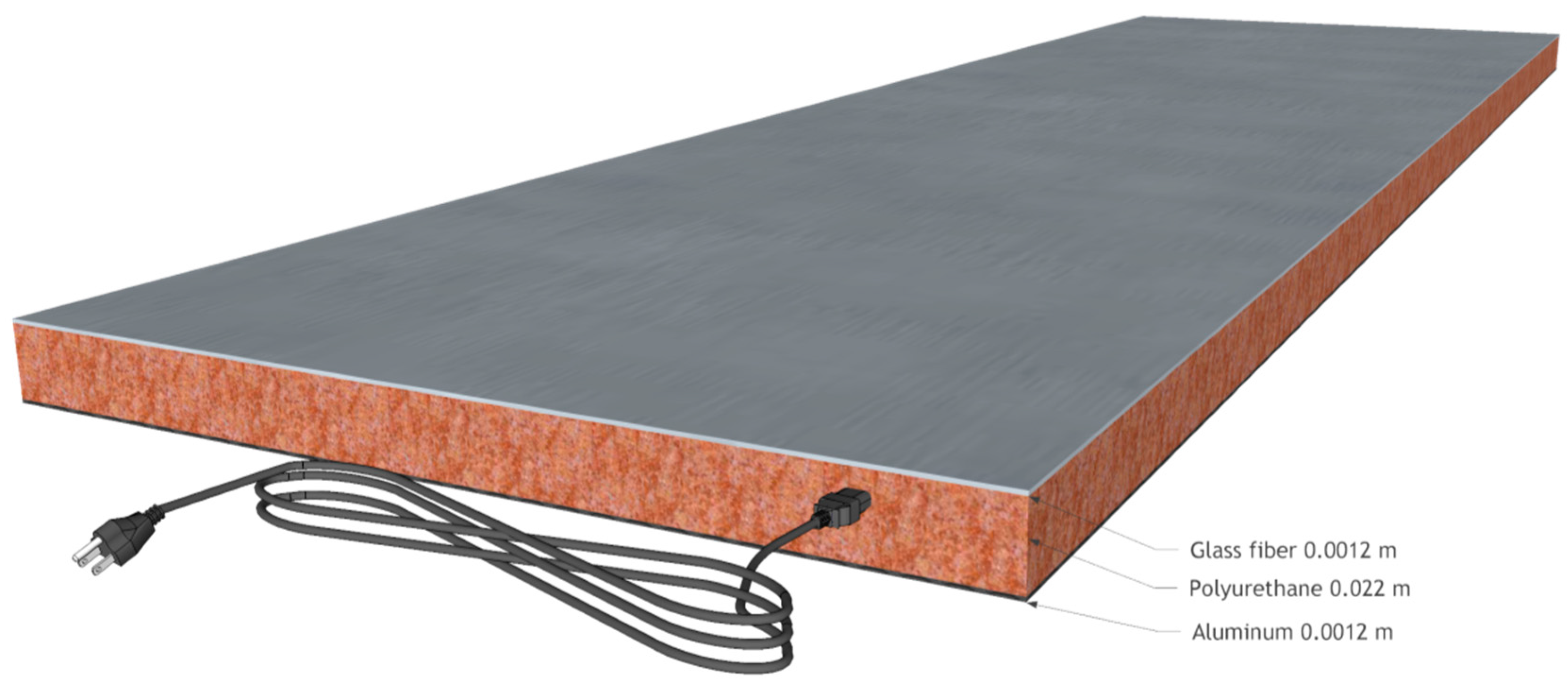
2.1. Radiant Heating Panel

The electric radiant heating panel works by Joule effect. The active part is essentially made of metallic materials through which the electric current flows. Given the electric resistance R of the metallic material and the electric current I, the heating power delivered by Joule effect is given by P = I2R [W]. The radiant surface is covered with an electrical insulating material, to avoid electrical shock, and it is characterized by a high emissivity in the infrared band. The other surface of the panel is thermally and electrically insulated from the active surface. In the new types of panel, the wiring is made in such a way as to minimize the magnetic field due to the Alternating Current (AC) supply.
An electric radiant heating consists normally of the following layers:
  • Surface coating
  • Electric heaters
  • Insulating layer
The panel can be equipped with a room thermostat, power cord, and plug, for a quick connection to the mains. Usually, the control around the set point is of the on/off type, although in some systems it is possible to choose from multiple power levels, thereby regulating the amount of heat to the heating requirements of the building in a way similar to what happens in hydronic systems. Different supply voltages are used depending on the manufacturer and the application. In housing a low voltage is generally used, through the use of a transformer. In this case, powers ranging from 30 to 80 W m−2 are delivered, while with AC voltages powers of 300 W m−2 and over can be furnished.
The system’s flexibility is a clear advantage of this equipment: the electrical panels are connected to the power grid only through a plug; therefore, they can also be moved from one room to another one and integrated by other panels in case of need of higher heating power. The aspect of the need for maintenance, which is essentially absent, should also be mentioned. In contrast, the transformation efficiency of the electrical energy to heat by the Joule effect cannot exceed the unit value (systems based on heat pumps are characterized by Coefficient of Performance easily exceeding 1), and it is impossible to use the system for cooling. In addition, a standard contract for the supply from the national grid (generally around 3 kW) could be not enough to satisfy the high demand of the electric radiant heating panels.
The electrical panel used for the tests are manufactured in Italy; the available power range is between 300 W and 900 W, depending on 5 different sizes: 63 cm × 53 cm, 33 cm × 103 cm, 63 cm × 103 cm, 33 cm × 188 cm, 60 × 150 cm. The model 33 cm × 103 cm, 300 W, has been used for testing.
Currently, there are no regulations or standards for the design, installation, and assessment of the performance of the electric radiant systems. The only regulation that must be followed is the one in use for residential electrical systems with regard to the safety of the plant.

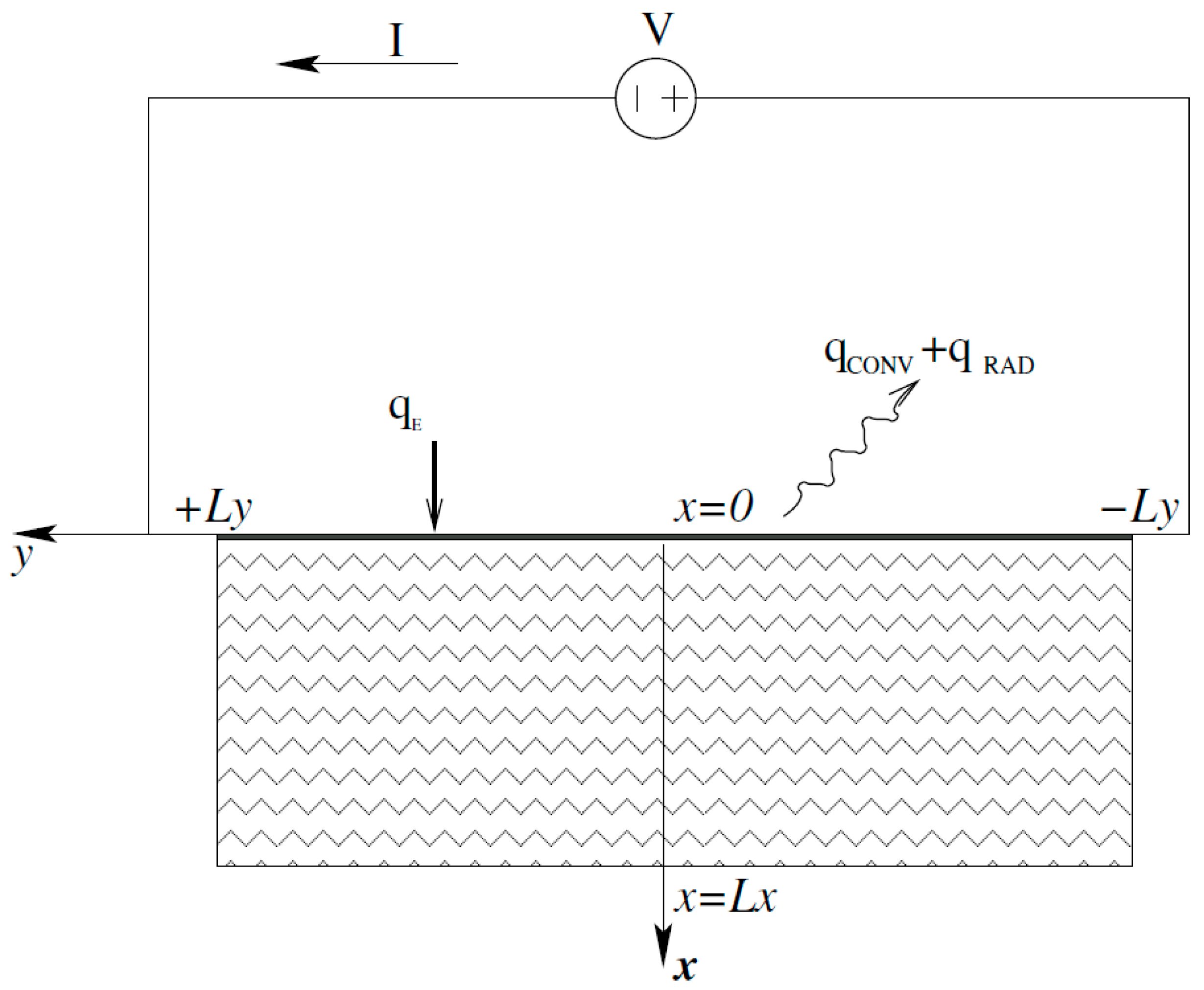
2.2. Mathematical Model

The electric radiant panel considered in the experiment is composed of a fiber glass layer on the front face, with embedded copper electrical conductors to provide heating by Joule effect, a polyurethane foam layer in the middle to limit the heat diffusion on the back, and an aluminum sheet on the rear side to guarantee mechanical strength and lightness at the panel. Scheme and dimensions of the panel are reported in Figure 1 and Table 1, respectively. In Table 1, the nominal values of the thermophysical properties of the different materials used in the panel are reported as well.
From the thermal point of view, the panel can be modeled as a hot plate of glass fiber with thickness Lx, adiabatic on the rear (due to the insulating layer of polyurethane), and extended on the plane yz with −Ly < y < Ly and −Lz < z < Lz, as shown in Figure 2. The panel is considered adiabatic on its lateral boundaries as well.
On its surface (the plane x = 0, y, z), a thin layer of a good electrical conductor is deposited with a negligible thickness. Heat is generated by Joule effect, uniformly distributed, in x = 0. The thickness of the glass fiber layer is small enough to consider negligible the characteristic time to propagate heat along the x direction in comparison with the dynamic of the whole system. Moreover, the temperature field is assumed to be uniform on the plane x = 0. It allows for the application a lumped formulation to solve the surface temperature variation as a function of time. The ordinary differential equation is [21]:
ρ c p L x d T d t = q E ( q C O N V + q R A D )
in which TT(t) is the temperature function of time t, ρ is density, and cp is specific heat at constant pressure. Initial conditions are as follows:
T = T 0 t = 0
in which:
  • the specific heat flux [Wm−2] generated on the surface by Joule effect is given by:
    q E = I 2 R 4 L y L z
    being I[A] the electric current and R[Ω] the electrical resistance;
  • the heat flux exchanged with the ambient at TAMB = T0 by convection is:
    q C O N V = h C O N V ( T ( x = 0 , t ) T 0 )
  • the heat flux exchanged with the ambient at TAMB = T0 by radiation is:
    q R A D = h R A D ( T ( x = 0 , t ) T 0 )
The last equation is the linearization of the well-known Stefan-Boltzmann equation according to the following scheme [22]:
q R A D = ϵ σ ( T 4 T 0 4 ) = ϵ σ ( T + T 0 ) ( T 2 + T 0 2 ) ( T T 0 ) = 2 ϵ σ ( T 2 + T 0 2 2 ) 4 ( T 2 + T 0 2 + 2 T T 0 2 T T 0 4 ) ( T T 0 ) = 8 ϵ σ T ¯ ( T 2 T T 0 2 ) ( T T 0 ) 4 ϵ σ T ¯ 3 ( T T 0 ) = h R A D ( T T 0 )
in which the following relations are applied:
T ¯ = T + T 0 2 ; T ¯ T T 0 T ¯ 3
With such a linearization the exchange coefficient by radiation, depending on the cube of the average value of the absolute temperature between the source and environment, is given by:
h R A D = 4 ϵ σ T ¯ 3
in which ε = [0, 1] is the emissivity of the emitting surface and σ = 5.67 × 10⁻⁸ [W m−2 K−4] is the Stefan-Boltzmann constant. For example, around room temperature (T average equal to 300 [K]) and with an emissivity value ε = 0.9, the exchange coefficient by radiation is hRAD = 5.5 [W m−2 K−1], while at T average equal to 373.15 [K], hRAD is equal to 10.6 [W m−2 K−1].
After switching on the radiant heating panel, a heat front starts to propagate along the x axis. Because the material has small thickness, heat reaches the other side of the layer almost immediately, and temperature increases according to Equation (1) [21]. It is then possible to write the ordinary differential equation:
θ + h C O N V + h R A D ρ c p L x θ = 0
in which:
θ = 1 ρ c p L x [ q E ( h C O N V + h R A D ) ( T T 0 ) ]
The solution is:
θ = q E ρ c p L x e h C O N V + h R A D ρ c p L x t
that could be rewritten as:
T ( t ) T 0 = q E h C O N V + h R A D [ 1 e h C O N V + h R A D ρ c p L x t ]
Two groups of parameters, α and τ, could be identified:
α = q E h C O N V + h R A D ; τ = ρ c p L x h C O N V + h R A D
The parameter τ is the time constant of the system. This value is of particular interest for the designers, as it defines the mode of operation of the panel and significantly contributes to establishing the thermal comfort in the rooms in which the panel is applied.

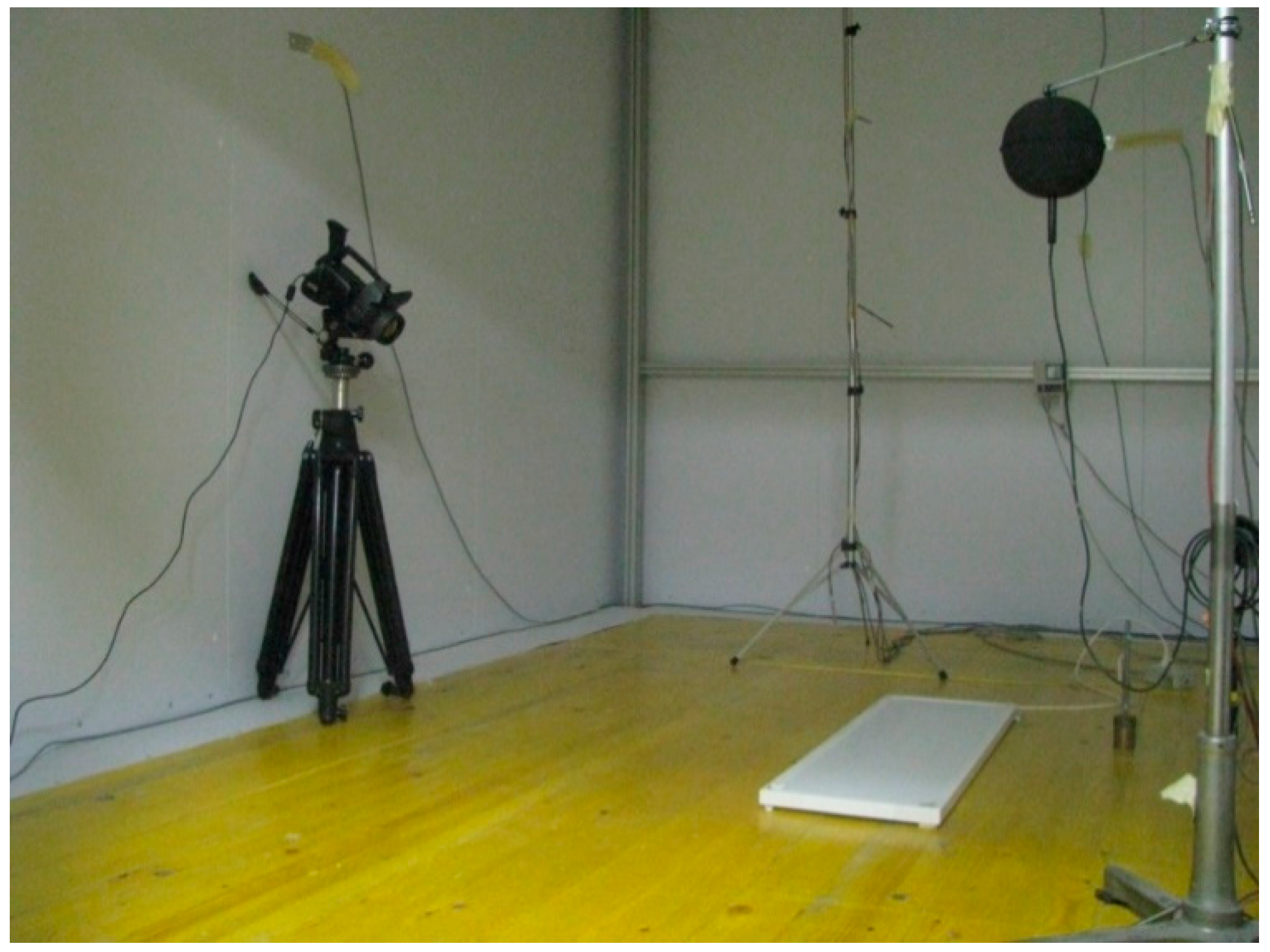
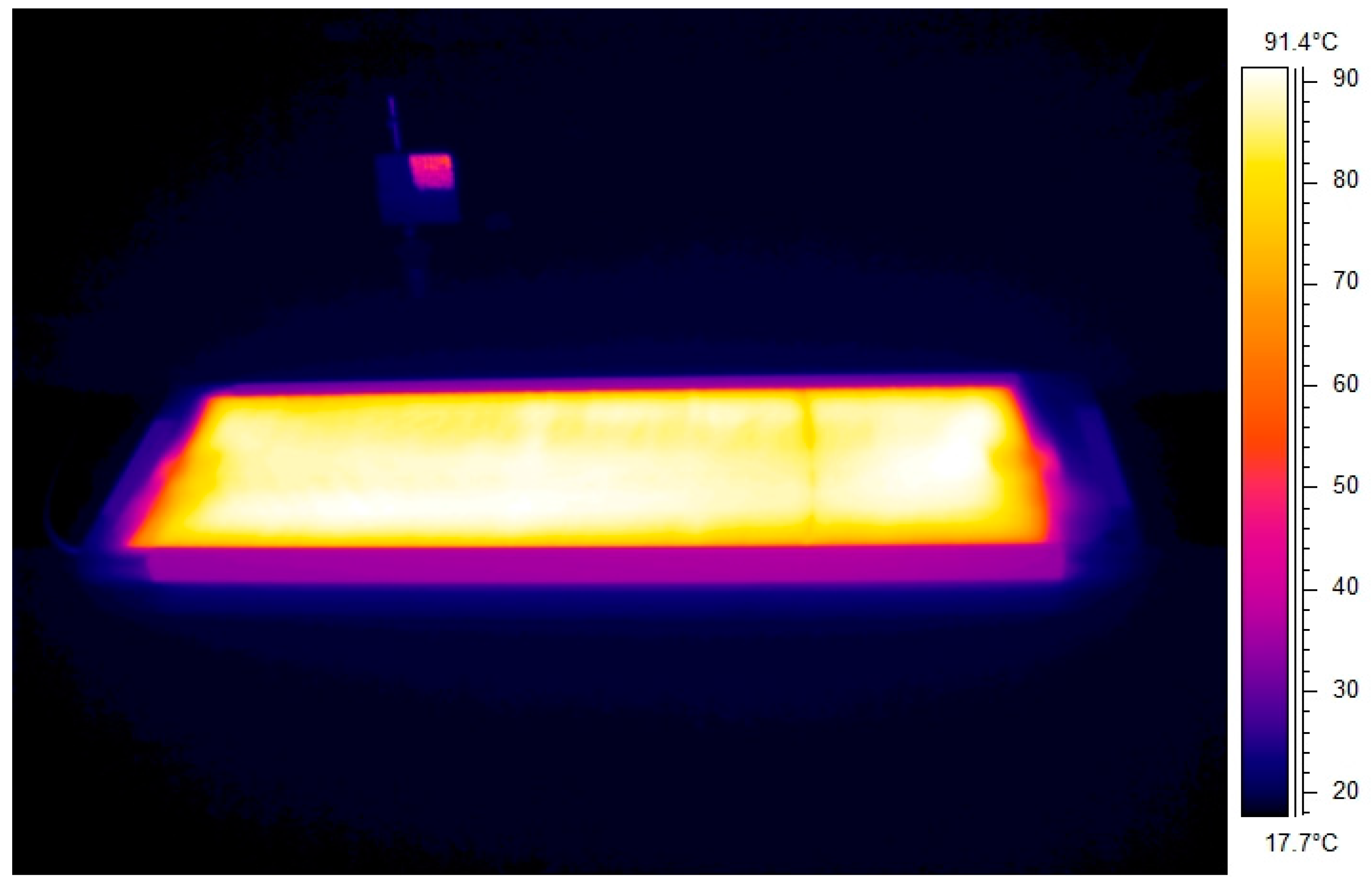
2.3. Experimental Layout–Thermal Testing

The European Committee for Standardization (CEN) and the International Organization for Standardization (ISO) propose detailed standards for testing and designing water heating and cooling panels both for floor and ceiling applications [23,24,25]. In this work, a commercial standalone electric radiant heating panel has been tested with the aim of being able to evaluate the performance in a controlled space. For this purpose, the climatic room of the Institute for Construction Technologies in Padova (Italy) has been utilized. The room is placed inside a building, and it is constituted by a thermally insulated chamber made of panels with a thickness of 5 cm and thermal conductivity of 0.04 W m−1 K−1. The internal dimensions are equal to 4.36 m × 8.42 m × 3.45 m: the floor surface is therefore equal to 36.71 m2, and the total volume is equal to 126.5 m3. The room is completely surrounded by an empty cavity in which air flows with a maximum flow rate value equal to 7000 m3 h−1: the air temperature is controlled by an air treatment unit. The air temperature in the cavity allows for the control of the conditions of the surface temperature of the test room. The air temperature inside the cavity is controlled in a continuous way around the setpoint to maintain a very stable internal operating temperature during the measurements: the distribution of surface temperature is in the range of ±0.3 °C. The air treatment unit is connected to a reversible heat pump that provides heating and cooling. The heat pump is a Carrier 30RH 005 model, 5.1 kW nominal cooling capacity, 5.7 kW nominal heating capacity, 2.02 kW power consumption for cooling, and 2.09 kW power consumption for heating.
Inside the climatic test room, an insulated chamber was installed above the existing floor. The new room was built with sandwich panels of expanded foam (polyurethane) and fiberglass-reinforced epoxy resin, white painted with medium-high emissivity varnish (0.75 in the long wave infrared band) on both inner and outer side. The polyurethane foam layer has a thickness of 70 mm and a thermal conductivity of 0.023 W m−1 K−1; the thermal transmittance is equal to 0.33 W m−1 K−1. The external dimensions of the room are equal to 3.34 m × 4.41 m × 3.15 m. The dimensions are therefore compatible with those provided by the standard UNI EN 14240 [25] for the test of radiant ceiling systems. Inside the chamber a water-radiant ceiling was installed, made by 6 modules connected in three parallel series of 2 modules each. The inlet and outlet pipes are connected to a system placed outside the cell, which delivers either hot or cold water.
The maintenance of the operating conditions and their measurement are obtained with a network of sensors and actuators and controlled by a real time system. This system is supervised by a computer through the internet network. The control and measurement software was developed in LabView platform. All the temperature sensors have been calibrated in the laboratory, while the flow sensors were verified after the installation of the electric radiant panel. Table 2 summarizes the type and number of sensors utilized in the hot/cold water generation system. Table 3 describes the sensors utilized inside and outside the test chamber.
More in detail, the temperature sensors for air and the wall were placed in the following way:
  • 4 contact temperature sensors for the walls, one for each of the four outer walls of the test chamber;
  • 4 air temperature sensors placed near the side of the entrance door of the test chamber at 0.1 m, 1.1 m, 1.7 m, and 2.5 m height;
  • 4 air temperature sensors placed near the opposite side of the entrance door of the test chamber at 0.1 m, 1.1 m, 1.7 m, and 2.5 m height;
  • 4 air temperature sensors placed in the climatic room that encloses the test chamber (one for each side of the cell);
  • 1 contact temperature sensor placed on the floor of the test chamber;
  • 2 temperature sensors placed on the radiant ceiling, one at the inlet of a series of panels, the other one in a point of the ceiling not occupied by panels;
  • 2 globe thermometers placed on the side of the entrance door of the test chamber and on the opposite side at the height of 1.1 m for the measurement of the average radiant temperature;
  • 3 temperature sensors placed in the space between the radiant ceiling and the ceiling of the room, one in contact with the ceiling of the cell, one in contact with the radiant ceiling, one that measures the temperature of the air in the cavity.
The electric radiant panel was installed in the middle of the floor inside the test chamber. Its nominal power is 300 W, and the dimensions are 103 by 33 cm. A picture of the experimental setup is shown in Figure 3.
The thermal camera used during the experiments is a FLIR SC660, having a spectral response 7.5 μm and 13.5 μm, a noise equivalent temperature difference (NETD) lower than 30 mK, a resolution equal to 640 × 480 pixel.

2.4. Measurement Procedure

The measurement procedure is different for the steady state and for the transient analysis. In the first case, the active ceiling is set on cooling mode and the panel is turned on. The electric radiant panel is controlled in order to generate the power required to balance the heat absorbed by the ceiling; in this way also, the internal temperature of the testing chamber is maintained constant. The time needed by the system to reach the steady state condition is higher than 24 h.
The transient test starts with the radiant panel switched off; its surface temperature is equal to the temperature of the chamber, which is defined as TENV. Successively, the panel is switched on at its nominal power (300 W) and the increase of its surface temperature is recorded with the thermal camera. The camera acquires an image of the panel every 10 s. A special infrared target, connected to a contact temperature probe, is placed inside the field of view of the camera: this allows both to correct the offset of the thermal camera on the absolute temperature measurement, and to estimate the air temperature variation and the reflected temperature [26].

3. Results

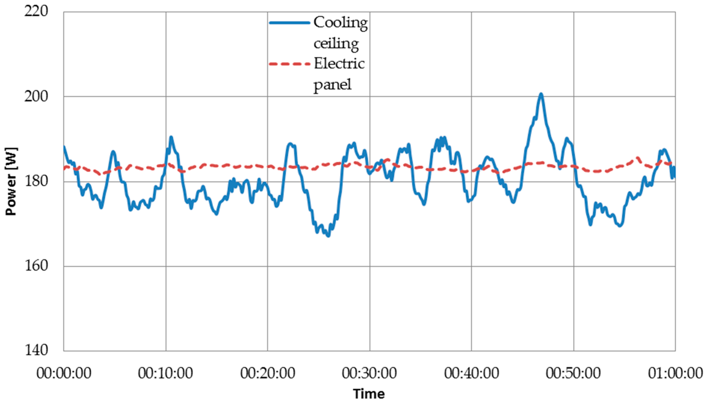
3.1. Steady State Thermal Conditions

Two measurements of the thermal efficiency of the panel were conducted by setting the maximum cooling power of the ceiling, which is about 235 W, and 60% of this value. The internal temperature of the room was kept approximately at 20 °C for both tests. The electric radiant panel was controlled in order to generate the power required to balance the heat absorbed by the ceiling. In this way, also the internal temperature of the cell was maintained constant.
Figure 4 shows the trend of the electrical power absorbed by the panel (energy input) and the thermal power absorbed by the ceiling (energy extraction) from the test room under steady state conditions. The collected data refer to one hour and are recorded after the period required for achieving steady state condition. It can be noted that the electrical power absorbed by the panel is slightly greater than the enthalpic power absorbed by the ceiling; this indication is confirmed by comparing the average values that are, respectively, 181 W and 183.4 W. The uncertainty values during the measurement for the two power values were, respectively, ±6 W and ±0.6 W, calculated as proposed in [27,28].
The relationship between the measured values makes it possible to estimate the emission efficiency of the panel, which is equal to 0.99 ± 0.03, a value comparable with the data available in the literature. It should be also noted that the upper limit of the emission efficiency is, by definition, equal to one. The energy losses of the heat emission system mainly depend on:
(a)
energy need for space heating (and as consequence from thermal properties of building envelope and indoor/outdoor boundary conditions);
(b)
non-uniform indoor air temperature distribution (i.e., due to stratification or plane radiant asymmetry);
The additional energy losses can be caused by increased internal temperature and heat transfer coefficient near windows, and by convection and radiation from the heat emission system through other outside surfaces. Furthermore, energy losses can be caused by additional transmission to the outside and apply to floor heating, ceiling heating, and wall heating systems and similar. However, this is only considered as a loss, when one side of the building part containing the embedded heating device is facing the outside, the ground, an unheated space, or a space belonging to another building unit. For each electrical device of the heat emission system, electrical power consumption, the duration of operation, and the part of the electrical energy converted to heat and emitted into the heated space shall be taken into account [29].

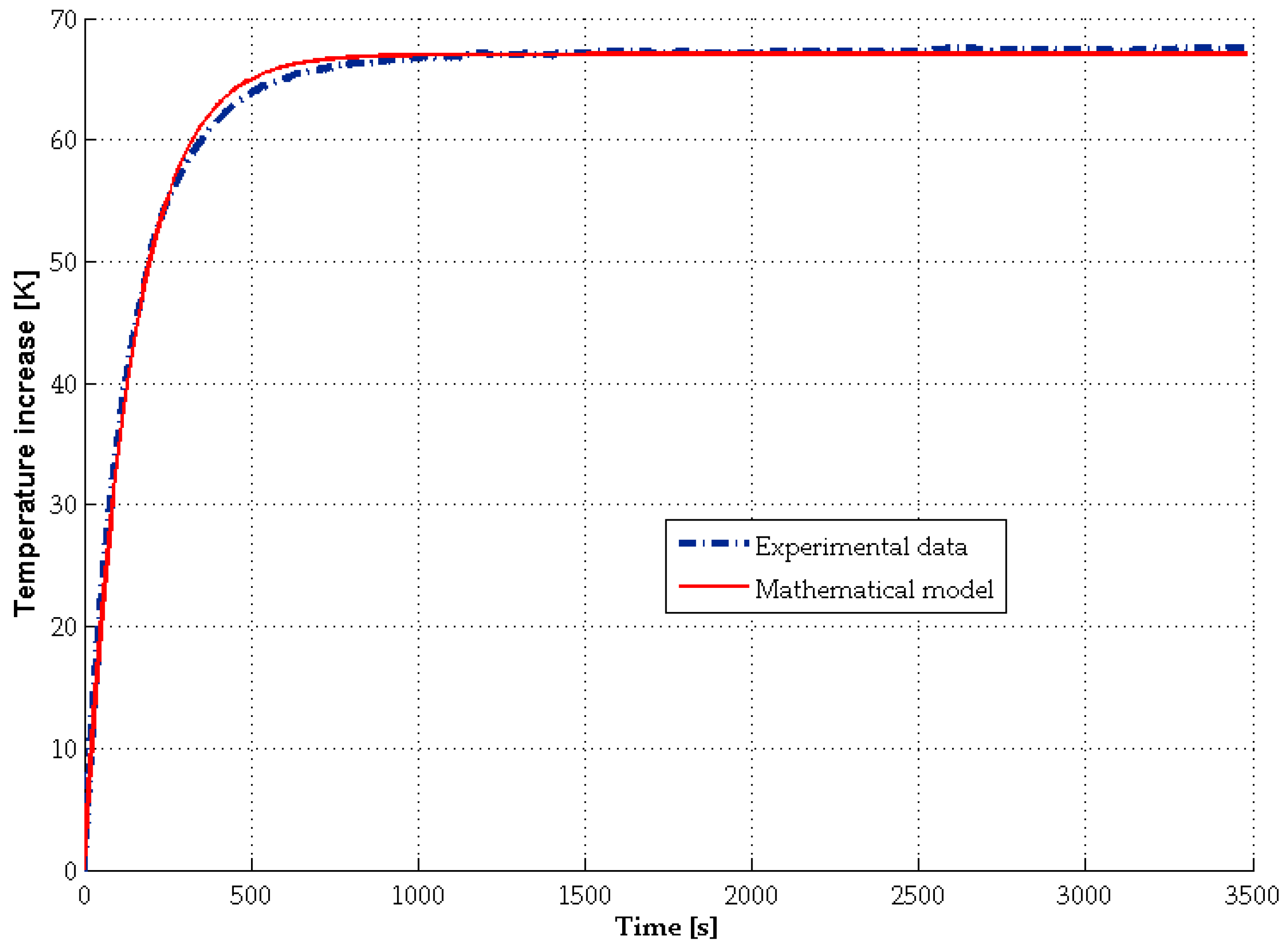
3.2. Transient Thermal Conditions

After the tests in steady condition, the dynamic behavior of the panel was investigated with a different testing procedure. The surface temperature of the panel increases rapidly until reaching a stable average value of 86 °C. Measuring the temperature increase with a contact temperature probe could have instead lead to underestimation or overestimation of the temperature. A contact probe is representative of a single point of the panel, but the heating, even on small panel, is not homogenous. Only the use of infrared thermography overcomes this issue, allowing the evaluation of the entire heating surface. Figure 5 shows the average temperature increase of the surface, taking into account the environment temperature recorded during the test, which was close to 18 °C. The experimental temperature profile is compared against the mathematical model, as described in Section 2.2. The curve is obtained fitting the measured data with the least square method. The root mean squared error of the fit is equal to 0.32 [K].
The model allows the estimation of the parameters α and τ described in Equation (13). The obtained values are, respectively, 67 K and 144 s. The α value, considering the declared power of the panel of 300 W, gives an estimated value close to 15 W m−2 K−1 for the total heat exchange coefficient, which is compatible with the mathematical model. Due to the nature of the electric panel, the value of the time constant τ value is lower than the ones calculated for several hydronic systems available in the literature [30].
Infrared measurement gives also information on the surface temperature distribution. From the thermal image (Figure 6) obtained at the end of the test, it is possible to note that some zones of the panel, in correspondence to the cabling system, differ from the average temperature.

4. Discussion

This work developed experimental procedures that allowed the measurement of the thermal performance of electric radiant heating panels. For the steady state measurement, the methods and the equipment are similar to the one applied for water based radiant systems; therefore, the results can be compared. The emission efficiency of these devices was found slightly lower than one, a value that is similar to the literature data for other systems and that is necessarily lower than the unit, due to heat transmission laws.
For the transient measurement, the data obtained during the test can be compared with those reported in the literature for other systems. The mathematical model allows for the quantitative evaluation of the thermal behavior of the system thanks to the definition of the α and τ parameters. It is possible to observe that a system with radiant electric panels could be more reactive than a standard hydronic system. This is due to the much lower thermal inertia of the electrical radiant panel compared to a typical hydronic system; as consequence, the electrical panel employs less time to reach a steady state condition. Great care should be taken when comparing the overall performance between electrical and water-based panels, as this analysis should always consider primary energy, and in several countries this has had a dramatic impact on the global evaluation.
The application of infrared thermography is particularly suited to the transient test, which, with some modifications, could be also performed on-site. Future work will investigate the practical feasibility of the on-site monitoring, as it would be a valuable tool for home inspectors and building designers.

Acknowledgments

This project was partially supported by the European Social Fund-Project 2122/1/12/1686/2012.

Author Contributions

G.F., P.B., F.P., and P.R. conceived and designed the experiments; G.F., S.F., and A.B. performed the experiments; S.F. and G.C. analyzed the data; P.B. contributed for the mathematical model; G.F., P.B. and P.R. wrote the paper.

Conflicts of Interest

The authors declare no conflict of interest.

Nomenclature

LxPanel thickness [m]
LyPanel half length [m]
LzPanel half width [m]
VVoltage [V]
PElectrical Power [W]
IElectric Current [A]
TTemperature [K]
ρDensity [kg m−3]
cpSpecific heat [J kg−1 K−1]
qEHeat flux given by Joule effect [W m−2]
qCONVConvective heat flux [W m−2]
qRADRadiant heat flux [W m−2]
tTime [s]
RElectrical resistance [Ω]
hCONVConvective heat coefficient [W m−2 K−1]
hRADRadiant heat coefficient [W m−2 K−1]
εEmissivity [a.u.]
σStefan-Boltzmann constant [W m−2 K−4]
T ¯ Temperature average [K]
θLaplace transform of the temperature
αPanel asymptotic temperature [K]
τTime constant of the system [s]
TENVTemperature of the environment [K]

References

  1. Bean, R.; Olesen, B.W.; Kim, W.W. History of Radiant Heating & Cooling Systems, Part 2. ASHRAE J. 2010, 52, 50–55. [Google Scholar]
  2. Lin, K.; Zhang, Y.; Xu, X.; Di, H.; Yang, R.; Qin, P. Experimental study of under-floor electric heating system with shape-stabilized PCM plates. Energy Build. 2005, 37, 215–220. [Google Scholar] [CrossRef]
  3. Seo, J.; Jeon, J.; Lee, J.-H.; Kim, S. Thermal performance analysis according to wood flooring structure for energy conservation in radiant floor heating systems. Energy Build. 2011, 43, 2039–2042. [Google Scholar] [CrossRef]
  4. Miriel, J.; Serres, L.; Trombe, A. Radiant ceiling panel heating–cooling systems: Experimental and simulated study of the performances, thermal comfort and energy consumptions. Appl. Therm. Eng. 2002, 22, 1861–1873. [Google Scholar] [CrossRef]
  5. Andrés-Chicote, M.; Tejero-González, A.; Velasco-Gómez, E.; Rey-Martínez, F.J. Experimental study on the cooling capacity of a radiant cooled ceiling system. Energy Build. 2012, 54, 207–214. [Google Scholar] [CrossRef]
  6. Khanna, A. Development and Demonstration of a Performance Test Protocol for Radiant Floor Heating Systems. Available online: http://theses.lib.vt.edu/theses/available/etd-01182006-011730/ (accessed on 20 November 2017).
  7. Diaz, N.F.; Lebrun, J.; André, P. Thermal modeling of the cooling ceiling systems as commissioning tool. In Proceedings of the 11th International Building Performance Simulation Association Building Simulation Conference, Glasgow, Scotland, 27–30 July 2009. [Google Scholar]
  8. Sattari, S.; Farhanieh, B. A parametric study on radiant floor heating system performance. Renew. Energy 2006, 31, 1617–1626. [Google Scholar] [CrossRef]
  9. De Carli, M.; Peron, F.; Romagnoni, P.C.; Zecchin, R. Computer simulation of ceiling radiant heating and cooling panels and comfort evaluation. In Proceedings of the International Congress Healthy Buildings, Espoo, Finland, 6–10 August 2000; Volume 2, pp. 623–628. [Google Scholar]
  10. Weitzmann, P.; Kragh, J.; Roots, P.; Svendsen, S. Modelling floor heating systems using a validated two-dimensional ground-coupled numerical model. Build. Environ. 2005, 40, 153–163. [Google Scholar] [CrossRef]
  11. De Carli, M.; Scarpa, M.; Tomasi, R.; Zarrella, A. DIGITHON: A numerical model for the thermal balance of rooms equipped with radiant systems. Build. Environ. 2012, 57, 126–144. [Google Scholar] [CrossRef]
  12. Cantavella, V.; Bannier, E.; Silva, G.; Muñoz, S.; Portolés, J.; Algora, E.; Garcia, M.A. Dynamics of thermal performance of an electric radiant floor with removable ceramic tiles. In Proceedings of the 2010 11th World Congress on Ceramic Tile Quality, Castellon, Spain, 15–16 February 2010. [Google Scholar]
  13. Samek, L.; De Maeyer-Worobiec, A.; Spolnik, Z.; Bencs, L.; Kontozova, V.; Bratasz, Ł.; Kozłowski, R.; Van Grieken, R. The impact of electric overhead radiant heating on the indoor environment of historic churches. J. Cult. Herit. 2007, 8, 361–369. [Google Scholar] [CrossRef]
  14. Camuffo, D.; Pagan, E.; Schellen, H.L.; Limpens-Neilen, D.; Kozlowski, R.; Bratasz, L.; Rissanen, S.; Van Grieken, R.; Spolnik, Z.; Bencs, L.; et al. Church Heating and Cultural Heritage Conservation: Guide to the Analysis of Pros and Cons of Various Heating Systems; Mondadori Electa: Milano, Italy, 2006; ISBN 978-88-370-5034-4. [Google Scholar]
  15. European Commission. Friendly Heating: Confortable to People and Compatible with Conservation of Art Works Preserved in Churches; FP5-EESD-EVK4-CT-2001-00067; European Commission: Brussels, Belgium, 2005. [Google Scholar]
  16. Ministero dello Sviluppo Economico. Decreto Interministeriale 26 Giugno 2015—Applicazione delle Metodologie di Calcolo delle Prestazioni Energetiche e Definizione delle Prescrizioni e dei Requisiti Minimi Degli Edifici; Ministero dello Sviluppo Economico: Rome, Italy, 2015.
  17. Meola, C. Infrared Thermography in the Architectural Field. Sci. World J. 2013, 2013, e323948. [Google Scholar] [CrossRef] [PubMed]
  18. Lucchi, E. Applications of the infrared thermography in the energy audit of buildings: A review. Renew. Sustain. Energy Rev. 2017, 82, 2077–3090. [Google Scholar] [CrossRef]
  19. Cadelano, G.; Bison, P.; Bortolin, A.; Ferrarini, G.; Peron, F.; Girotto, M.; Volinia, M. Monitoring of historical frescoes by timed infrared imaging analysis. Opto-Electron. Rev. 2015, 23, 102–108. [Google Scholar] [CrossRef]
  20. Ferrarini, G.; Bison, P.; Bortolin, A.; Cadelano, G. Thermal response measurement of building insulating materials by infrared thermography. Energy Build. 2016, 133, 559–564. [Google Scholar] [CrossRef]
  21. Arpaci, V.S. Conduction Heat Transfer; Addison-Wesley Pub. Co.: Boston, MA, USA, 1966. [Google Scholar]
  22. Jaeger, J.C. Conduction of heat in a solid with a power law of heat transfer at its surface. Math. Proc. Camb. Philos. Soc. 1950, 46, 634–641. [Google Scholar] [CrossRef]
  23. Italian Organization for Standards. UNI EN 1264—Water Based Surface Embedded Heating and Cooling Systems; Italian Organization for Standards: Milano, Italy, 2009. [Google Scholar]
  24. British Standards Institution. EN 14037 Free Hanging Heating and Cooling Surfaces for Water with a Temperature below 120 °C; British Standards Institution: London, UK, 2015. [Google Scholar]
  25. UNI EN 14240 Ventilation for Buildings—Chilled Ceilings—Testing and Rating Cooling Capacity; European Committee for Standardization: Brussels, Belgium, 2005.
  26. Grinzato, E. Humidity and air temperature measurement by quantitative infrared thermography. Quant. InfraRed Thermogr. J. 2010, 7, 55–72. [Google Scholar] [CrossRef]
  27. Bevington, P.R.; Robinson, D.K. Data Reduction and Error Analysis for the Physical Sciences, 3rd ed.; McGraw-Hill: New York, NY, USA, 2003. [Google Scholar]
  28. International Bureau of Weights and Measures. Evaluation of Measurement Data—Guide to the Expression of Uncertainty in Measurement; JCGM 100:2008; International Bureau of Weights and Measures: Breteuil, France, 2008. [Google Scholar]
  29. British Standards Institution. UNI EN 15316-2:2017. Energy Performance of Buildings. Method for Calculation of System Energy Requirements and System Efficiencies. Space Emission Systems (Heating and Cooling); British Standards Institution: London, UK, 2017. [Google Scholar]
  30. Ning, B.; Schiavon, S.; Bauman, F.S. A novel classification scheme for design and control of radiant system based on thermal response time. Energy Build. 2017, 137, 38–45. [Google Scholar] [CrossRef]
Figure 1. Sketch of the radiant panel.
Applsci 08 00206 g001
Figure 2. Thermal model of the panel. The z axis is not represented in the image.
Applsci 08 00206 g002
Figure 3. Experimental setup with the radiant panel, the air temperature probes, and the thermal camera.
Applsci 08 00206 g003
Figure 4. Experimental data of the steady state measurement. The heating power generated by the electrical panel (red dashed line) is balanced by the radiant ceiling (blue solid line).
Applsci 08 00206 g004
Figure 5. Average surface temperature increase of the panel during the transient testing.
Applsci 08 00206 g005
Figure 6. Thermal image obtained at the end of the transient measurement.
Applsci 08 00206 g006
Table 1. Stratigraphy of the electric radiant panel.
LayerMaterialThickness [mm]Density [kg m−3]Specific Heat [J kg−1 K−1]Thermal Conductivity [W m−1 K−1]
FrontGlass fiber1.225008001.1
MiddlePolyurethane foam22.04014800.03
RearAluminum metal sheet1.22700800170
Table 2. Sensors of the hot and cold water generation system.
Type of MeasurementInstrumentQuantity
Water temperatureResistance Temperature Detector Pt1004
Water FlowElectromagnetic flowmeter1
Electrical powerVolt-Ampere meter1
Table 3. Sensors positioned inside and outside the test chamber.
Type of MeasurementInstrumentQuantity
Wall temperatureResistance Temperature Detector Pt10013
Air temperatureResistance Temperature Detector Pt1009
Water temperatureResistance Temperature Detector Pt1002
Mean radiant temperatureGlobe thermometer2
Heat fluxHeat flux meter1

