Article

Relationship between ISO 230-2/-6 Test Results and Positioning Accuracy of Machine Tools Using LaserTRACER

Center for Measurement Standards, Industrial Technology Research Institute, Hsinchu 30011, Taiwan
*
Author to whom correspondence should be addressed.
These authors contributed equally to this work.
Appl. Sci. 2016, 6(4), 105; https://doi.org/10.3390/app6040105
Submission received: 30 December 2015 / Revised: 27 March 2016 / Accepted: 29 March 2016 / Published: 12 April 2016
(This article belongs to the Special Issue Selected Papers from the 2015 International Conference on Inventions)

Abstract

:
To test the positioning accuracy and repeatability of the linear axes of machine tools, ISO (International Standards Organization) 230-2 and ISO 230-6 are usually adopted. Auto-tracking laser interferometers (ATLI) can perform the testing for the positioning accuracy and the repeatability including x-, y- and z-axes according to ISO 230-2 as well as xy, xz, yz, and xyz diagonal lines following ISO 230-6. LaserTRACER is a kind of ATLI. One of the steps of the ISO 230-2 and -6 tests using LaserTRACER is to determine the coordinate of the LaserTRACER with respect to the home point of the machine tool. Positioning accuracy of the machine tool causes the coordinate determined error, which might influence the test result. To check on this error, this study performs three experiments. The experiment results show that the positioning error appears on the testing results.

1. Introduction

There are 21 terms of error motion effecting spatial positioning accuracy of machine tools [1]. To improve the positioning accuracy and repeatability of machine tools, calibration and geometric error compensation are necessary. However, it is time consuming, and not all controllers suppose geometric error compensation, such as squareness, straightness, angular error motion and so on. The most basic CNC (computer (or computerized) numerical control) controller only provides linear positioning error compensation for machine tool performance improvement, but the improvement is limited. The procedure and method for linear axis positioning accuracy and repeatability measurement can be referred to ISO 230-2 and ISO 230-6 [2,3]. According to the ISO 230-2 and -6 standards, the linear positioning accuracy and the repeatability of x-, y- and z-axes as well as xy, xz, yz and xyz diagonal lines can be found. Note that we called the above-mentioned test the “seven lines test” in this study.
To perform the seven lines test, two instruments are preferred, a laser interferometer and an auto-tracking laser interferometer (ATLI). For the seven lines test, the spending time by means of a laser interferometer is about three times that of ATLI. To reduce the time required, multi-DOF (degree of freedom) measurement systems could be considered [4]. Although multi-DOF measurement systems can distinctly decrease the test time, the measurable range is usually smaller than a meter. Laser Tracker [5,6] and LaserTRACER [7,8,9] both belong to a kind of ATLI. The comparison of the measurement accuracy/uncertainty for different types of ATLIs is shown in Table 1. From the table, we can see that LaserTRACER is more suitable to apply to positioning accuracy and repeatability measurements for machine tools than others because of its smaller measurement uncertainty and smaller ranging errors [10]. For LaserTRACER, the target spatial position can be determined by multilateration [3,11,12]. To perform multilateration, multiple LaserTRACERs are needed. Combined with time sharing method [13] single LaserTRACER can also perform multilateration. Although the measurable distance of LaserTRACER (15 m) is smaller than Laser Tracker (over than 20 m), it is currently sufficient for general machine tools test. There are some other auto-tracking spatial measurement methods, such as that proposed by Lee et al. [14] using a Kinect to tracking a human body, as well as triangulation measurement method with dual modulated laser diodes and single detector [15,16]. Based on the concept of sphere surface refection, Lee et al. [17] propose a steel sphere center alignment device according to Michelson interference fringe deviation.
Figure 1 shows illustration of the basic structure of LaserTRACER. As seen in the figure, the laser beam is focused on the center of the steel sphere after passing through the lens and reflected by the steel sphere surface. The difference between Laser Tackers and LaserTRACER are as follows:
(1)
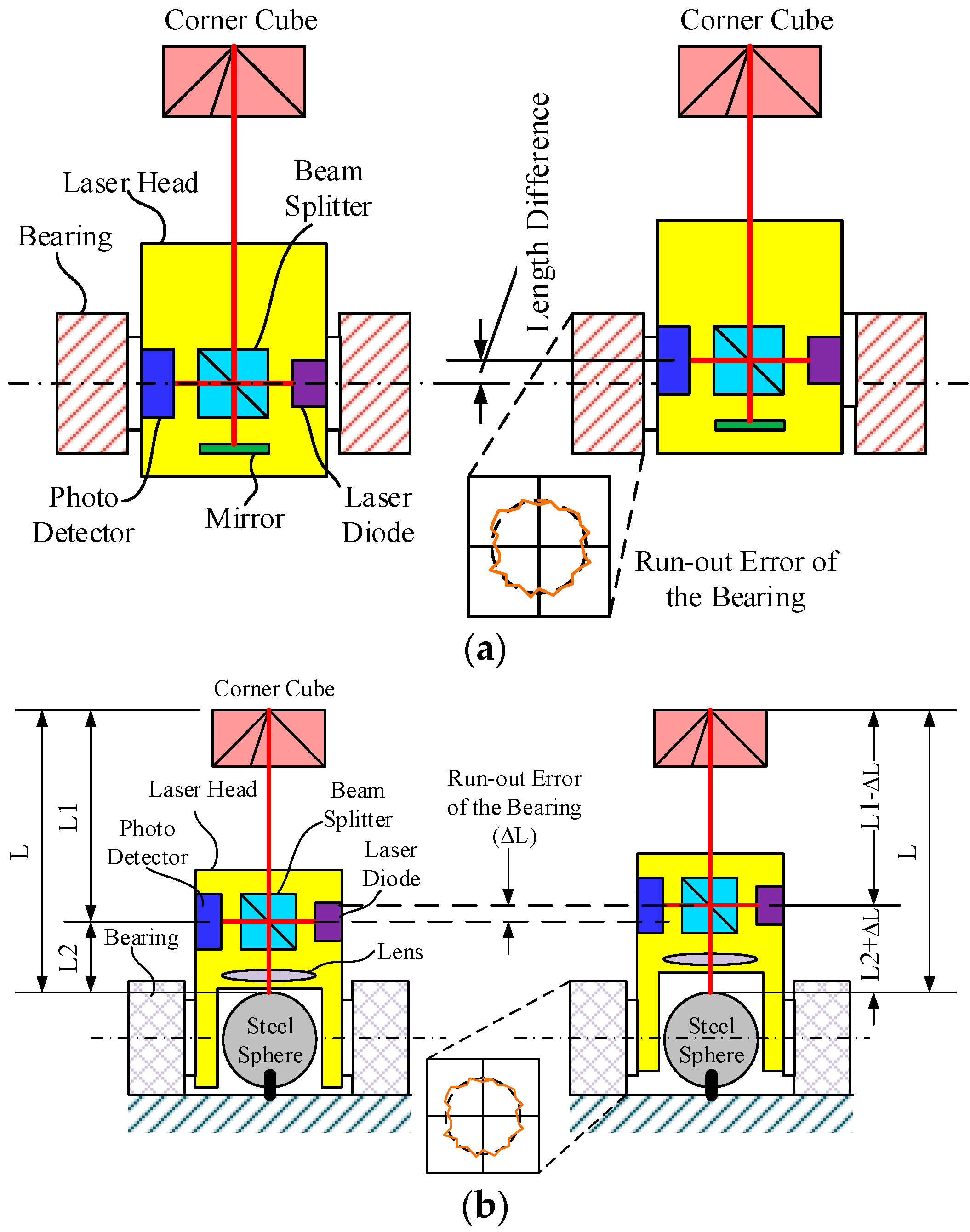
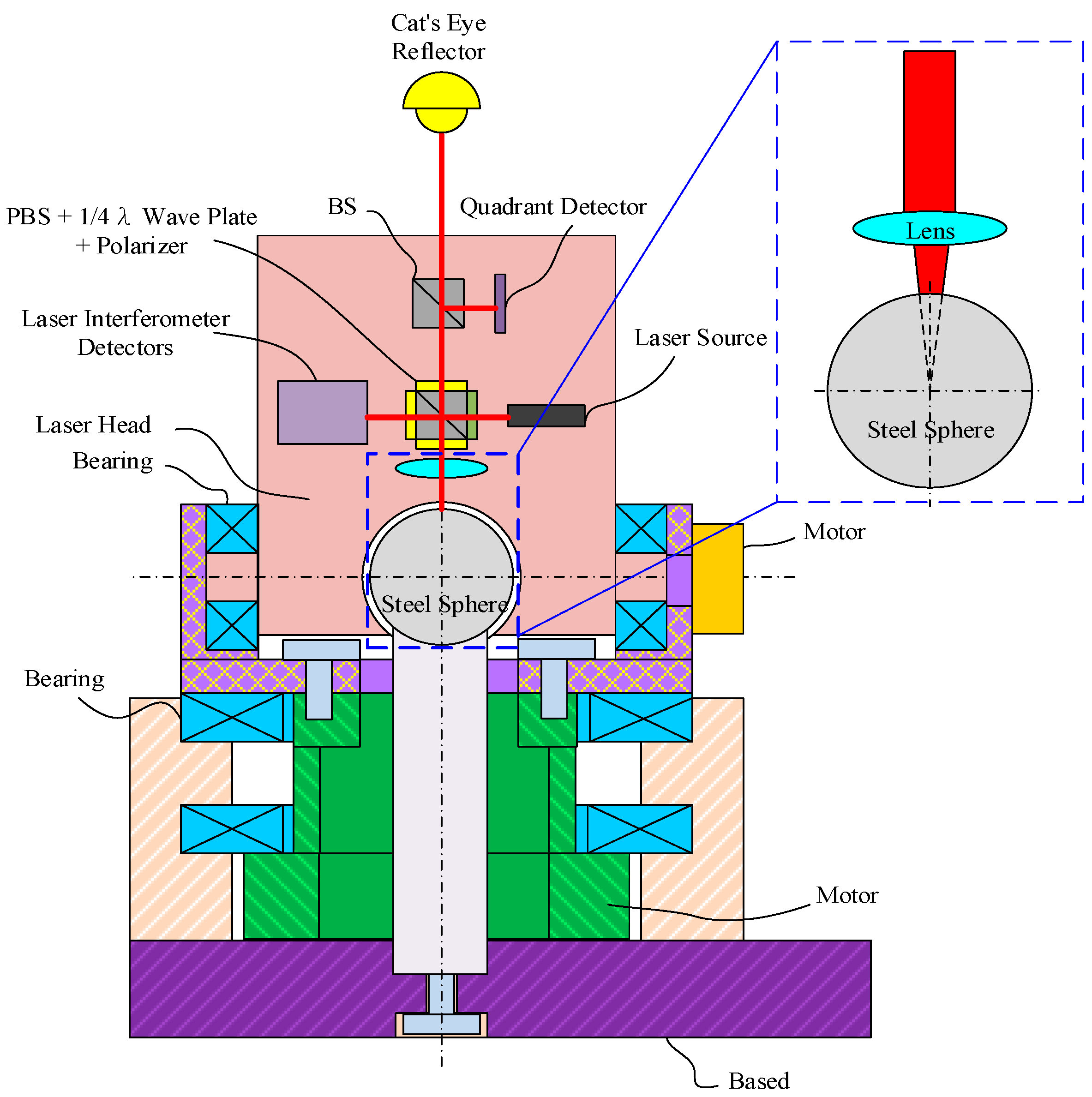
To reduce the measurement error due to bearing run-out error and mirror offset, LaserTRACER uses a steel sphere instead [18]. As seen in Figure 2a, when the laser head is rotated, the bearing run-out error affects the length difference. When a lens and a steel sphere are used instead, the run-out error can be eliminated, as shown in Figure 2b.
(2)
The target spatial coordinate, which is measured by Laser Tracker, is determined by the following Equation [19]:
{ d x + Δ x = ( d + Δ d ) cos ( β + Δ β ) cos ( α + Δ α ) d y + Δ y = ( d + Δ d ) cos ( β + Δ β ) sin ( α + Δ α ) d z + Δ z = ( d + Δ d ) sin ( β + Δ β )
where d represents the measured distance between the target and the Laser Trackers; α and β represent the angular position of θz and θy, respectively; and Δd, Δα and Δβ represent the deviations of d, α and β (i.e., the error sources), respectively.
(3)
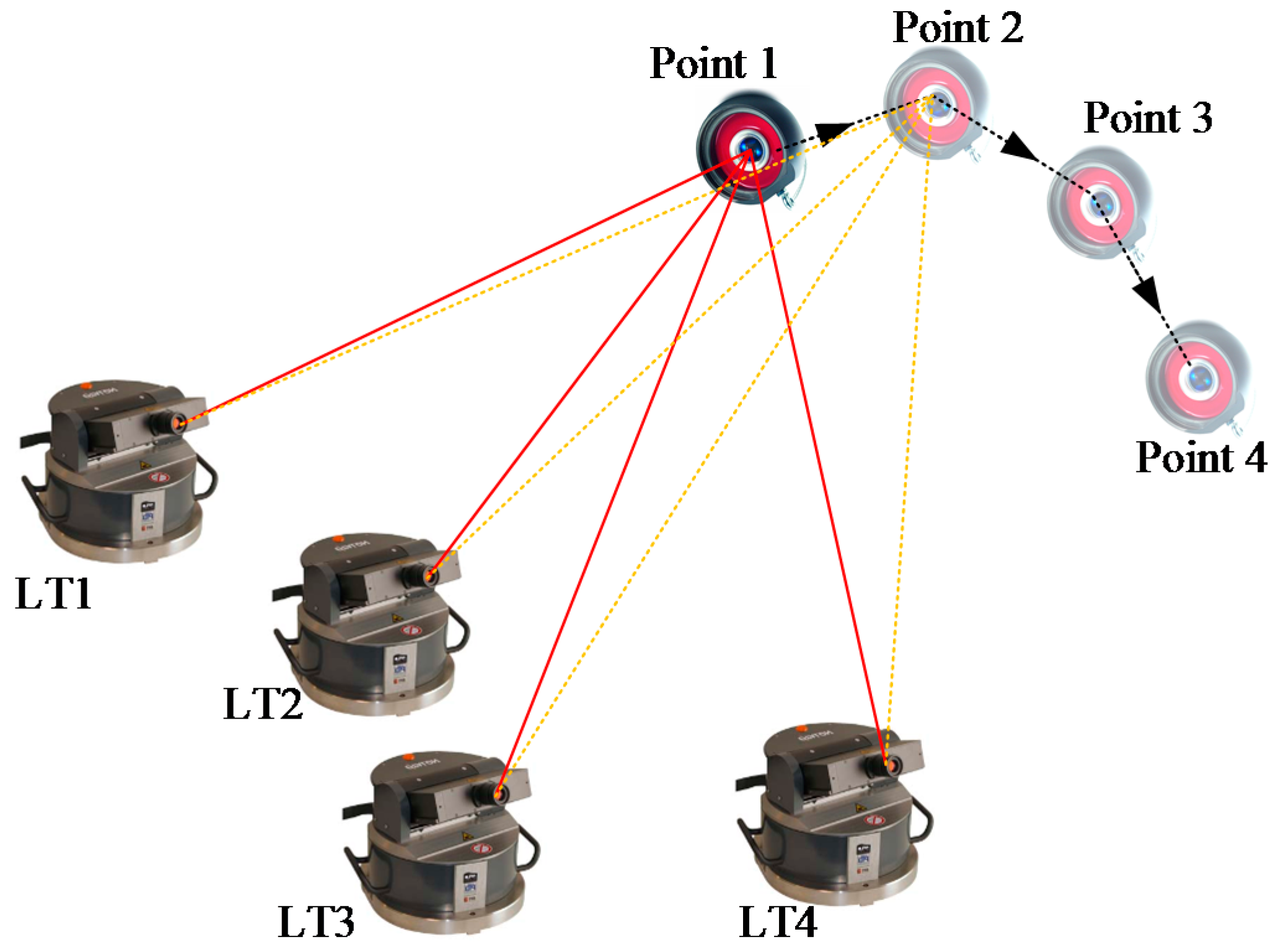
LaserTRACER adopts multilateration for spatial coordinate measuring, as shown in Figure 3. The measurement equation is as below [12]:
l ij + l oj + w ij = s j ( x i x 0 j ) 2 + ( y i y 0 j ) 2 + ( z i z 0 j ) 2
where ( x i , y i , z i ) is the coordinate of the i-th measurement point; ( x 0 j , y 0 j , z 0 j ) is the position of the j-th LaserTRACER; l i j is the measured length when the target stops at the i-th measurement point; l 0 j is the initial distance between the target and the j-th LaserTRACER; s j is the scale factor for j-th LaserTRACER, which can be determined through calibration; and w i j is the residual error.
The error terms of machine tool can be measured by multilateration combined with error model (or error mapping) of the machine tool [20,21]. There is a condition that should be stratified for using multilateration and LaserTRACER to measure the spatial coordinate of the target [13,22]:
5 × m + 3 × n m × n
where m represented the number of used LaserTRACER and n represented the number of the measurement points. From Equation (3), we can know that the equation can be solved if and only if m ≥ 4 and n ≥ 20. Please note that the measurement points should be independent of each other.
ISO 230-2 states that the test result should be corrected according to the measurement uncertainty. ISO 230-9 also shows a detailed explanation and ISO 230-2 gives two examples. The measurement uncertainties come from the measuring instrument, the compensation of the machine tool temperature, the environmental temperature variation error, and the misalignment of the measuring instrument. For example, if the traveling range of the axis is up to 2000 mm, the expanded measurement uncertainty (k = 2) of the mean positioning deviation is [3]:
U ( M ) = U instrument 2 + U misalignment 2 + U m , machine 2 + U m , instrument 2 + U e , machine 2 + U e , instrument 2 + 1 10 U EVE 2
where U instrument is the expanded uncertainty due to measuring instrument, which can be determined by measurement instrument calibration; U misalignment is the misalignment of measuring instrument to machine axis under test; U m , machine and U m , instrument are the expanded uncertainty due to measurement of temperature of the machine tool and the instrument, respectively; U e , machine and U e , instrument are the expanded uncertainty due to expansion coefficient for the machine tool and the measurement instrument, respectively; and U EVE and U m , instrument is the expanded uncertainty due to environmental variation error (e.g., drifting). Note that U m , instrument can be zero if U instrument includes the uncertainty due to the temperature measurement of the measurement instrument. Generally, misalignment of laser interferometer is smaller than 1 mm. Thus, if the machine axis under test is over than 300 mm, the measurement uncertainty of misalignment can almost be ignored.
LaserTRACER can work on two modes calibration and ISO test. Calibration mode uses more than four LaserTRACERs or one LaserTRACER with time sharing (i.e., multilateration method) and error mapping to compute the 21 terms of error motion compensation for three-axis machine tools [20,23]. Moreover, LaserTRACER can be applied to calibrate the rotary axes of machine tools [24] and can be applied to extra-small machine tool volumetric error compensation [25]. When LaserTRACER operated in ISO test mode, positioning accuracy of the machine tool causes measurement uncertainty because of misalignment. Since the behavior of misalignment of LaserTRACER is different than laser interferometers, for instance the angle between measurement axis and laser light is a function of measurement length for LaserTRACER, this study was performing three experiments to evaluating the influence of the test results due to misalignment which is caused by positioning accuracy of the machine tools.

2. Experiments

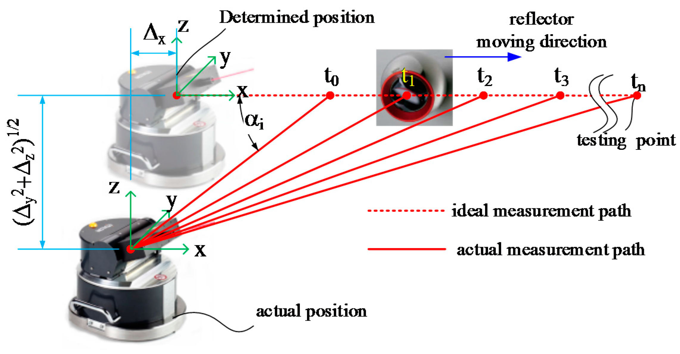
2.1. To Simulate the Error Motion

In section of SO 230-2 and ISO 230-6 Tests Using LaserTRACER, we show that the LaserTRACER (etalon AG, Braunschweig, Germany) coordinate determined error causes measurement length difference when the measured point is very closing to the LaserTRACER. In this section, our question is, could the positioning error of machine tools be found by ISO 230-2 and -6 tests even though the positioning error causes the LaserTRACER coordinate determined error. Thus, we performed the next three experiments. To decrease the influence of error motion of the tested machine tool, these experiments were carried out by means of a CMM (coordinate measuring machine).

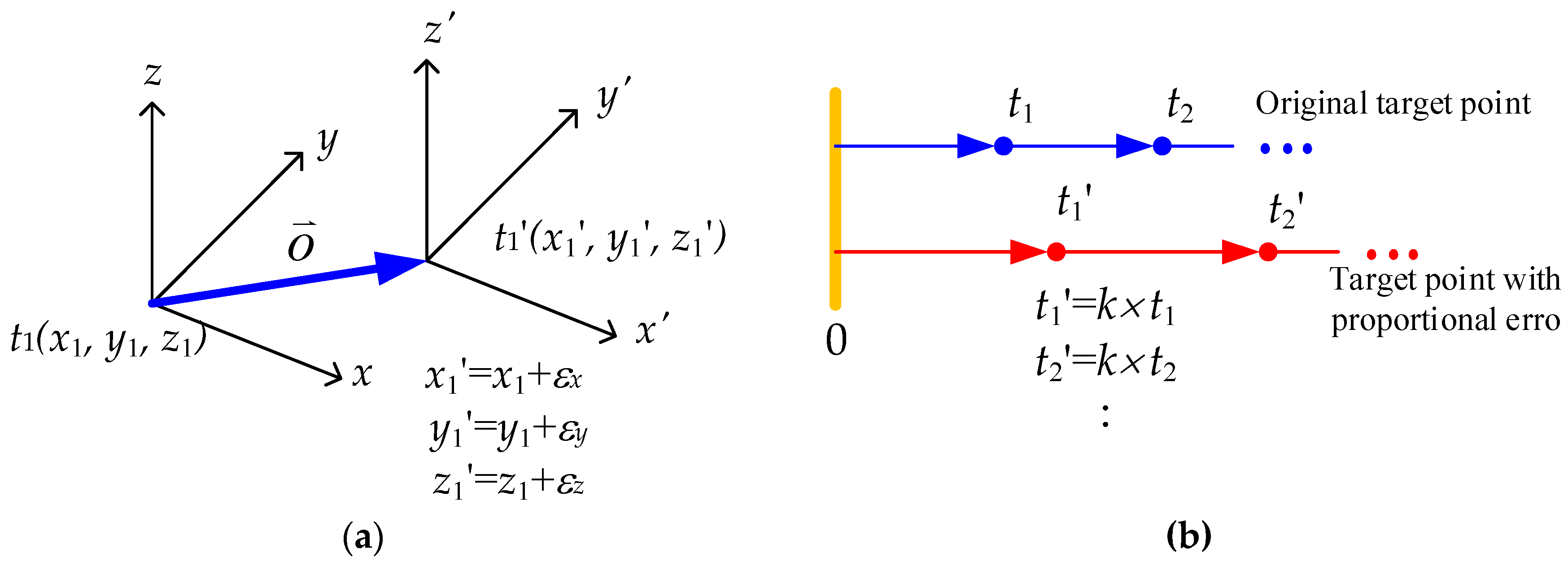
2.2. Coordinate Offset

The first experiment is to simulate the machine tool moved with a fixed (constant) positioning error. To simulate this situation, we give all measurement points of a constant offset, as seen in Figure 4a, where εx, εy and εz represent the amounts of the given coordinate offset. To easily observe the effect, we gave a large offset value for all points. For example, as seen in Table 2, we gave −1 mm offset for z-axis denoted of “z-axis, −1 mm”. The original coordinate of the LaserTRACER is (653.60, −27.13, 262.18) in unit of mm. After we gave the non-zero coordinate offset to different axes, the determined coordinate differences are listed in Table 2. From the results, we can see that the coordinate differences are almost exactly equal to the offset values that were given.
Because the coordinate difference is the negative of the given offset value, the coordinate offset can be cancelled. For example, assuming the actual position of the LaserTRACER is (100, 50, 30) mm, and the determined coordinate is (99, 50, 30) mm, when we give “z-axis, +1 mm”, the target points for x-axis testing will be:
( 99 + k × Δ s + s x + ε x + σ x , 50 , 30 ) ,
where k (= 1, 2, …, n, n represents the number of target points that is to be measured) denote the measurement point number, and; Δs denotes the interval distance of each point; sx denotes an offset distance along x-axis that was applied to avoid the reflector crashing the ATLI; εx represents the coordinate offset error (εx = 1); and σx represents the positioning error, including the repeatability. Thus, the measurement difference for each point is:
( 99 + k × Δ s + s x + ε x + σ x , 50 , 30 ) ( 100 + k × Δ s + s x , 50 , 30 ) = ( σ x , 0, 0 )
Assuming the testing axis yield the y-axis, the measurement points will be:
( 99 + ε x , 50 + k × Δ s + s y + σ y , 30 )
Thus, the measurement difference for each point is:
( 99 + ε x , 50 + k × Δ s + s y + σ y , 30 ) ( 100, 50 + k × Δ s + s y , 30 ) = ( 0, σ y , 0 )
From the results we can know that although the constant offset of the machine tool causes coordinate determined error, it does not affect the ISO 230-2 and -6 test results as well as the positioning error and repeatability of the testing axis can still be observed.

2.3. Proportional Error

To further check is the positioning accuracy cab be fully observed from the ISO 230-2 and -6 tests, the second experiment was performed. The second experiment was to give a proportional error for the target points, as seen in Figure 4b. Note that the proportional error is to simulate, as an example, the lead error of ball screw (assuming the ball screw has no backlash and hysteresis) in this study. The proportional error means that the actual position equals target position multiplying a constant (e.g., t = k × t ). There are two examples that we give:
(i)
Assuming the target point is (100, 50, 30.2) mm and the given proportional error for z-axis is 1.01, thus, the command position will be (100, 50, 30.804) mm.
(ii)
Assuming the target point is (82.55, 50, 30.2) mm and the given proportional error for z-axis is 0.99 for x-axis, the command position will be on (81.725, 50, 30.2) mm.
The experimental results are shown in Table 3. We can see that the coordinate determined error not only occurs on the axis that was giving the proportional error, but also appears in other axes. For instance, the actual and the determined coordinates of the LaserTRACER, respectively, locate at (100, 50, 30) and (100.60, 49.90, 29.99) mm of the experiment “x-axis, 1.01”. The measurement difference of x-axis test for each point is:
( 100 .60 + k × Δ s × p x + s x + σ x , 49 .9, 29 .99 ) ( 100 + k × Δ s + s x , 50 , 30 ) = ( 0 .60 + σ x + k × Δ s x × ( p x 1 ) , 0 . 10 , 0 .01 ) ,
where px represents the given proportional error. If the testing axis is y-axis, the measurement difference for k-th measurement point will be:
( 100 .60, 49 .9 + k × Δ s × p y + s y + σ y , 29 .99 ) ( 100, 50 + k × Δ s + s y , 30 ) = ( 0 .60, 0.10 + σ y + k × Δ s × ( p y 1 ) , 0 .01 )
From the experimental results, we can see that the measurement results included an error, as shown in Figure 5, and the proportional error could be observed.

2.4. ISO 230 Test with Proportional Error

To check whether the proportional error can be found from the ISO 230-2 and -6 tests, we performed ISO 230-2 and -6 tests for y-axis and xyz diagonal line. The testing results before we gave a proportional error are shown in Figure 6a. In Figure 6, the vertical axis represents the deviation value in unit of mm and the horizontal axis represents measurement length in unit of mm. Slop of δy is about −0.003% after curve fitting. After we gave a proportional error of 100.01% for y-axis, slop of δy is increasing to +0.007%, as shown in Figure 6b. To compare Figure 6a,b we can see that the amount of the slop deviation exactly equals to the proportional error that is we giving, and the shape of δxyz is also changed. The testing results also show the proportional error could be compensated by multiplying a constant.

3. ISO 230-2 and ISO 230-6 Tests Using LaserTRACER
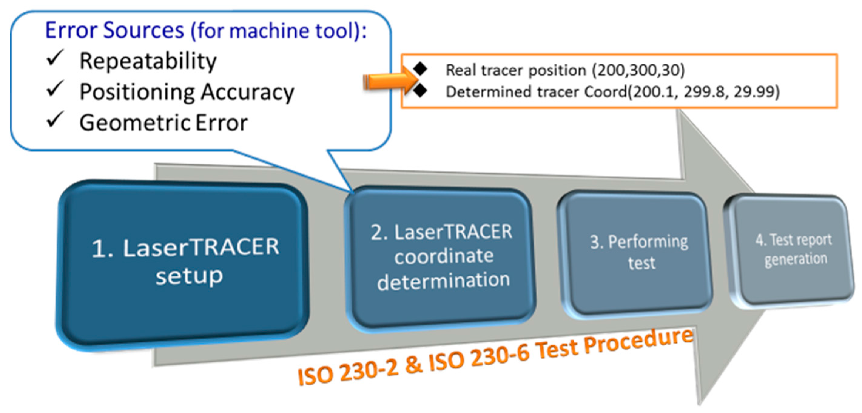
3.1. Test Procedure

Figure 7 shows the procedure of ISO 230-2 and -6 tests. For ISO 230-2 and -6 tests [2,3], one ATLI is used. The first step is to place and fix the LaserTRACER on the carriage of the machine tool. There are seven lines to be tested, namely δx, δy, δz, δxy, δxz, δyz and δxyz, as shown in Figure 8. Note that, for instance, δx and δxy represent the measured moving straight line of the machine tool along x-axis, and xy diagonal line, respectively. The next step is to determine the position of the ATLI related to the home/reference point of the machine tool. When the position of the LaserTRACER is determined, the measurement points for each test line will be computed and the NC (Numerical Control) code is generated. After users import the NC code to the machine tool, the seven lines testing can be performed. After test and data analysis are completed, the test report is generated.

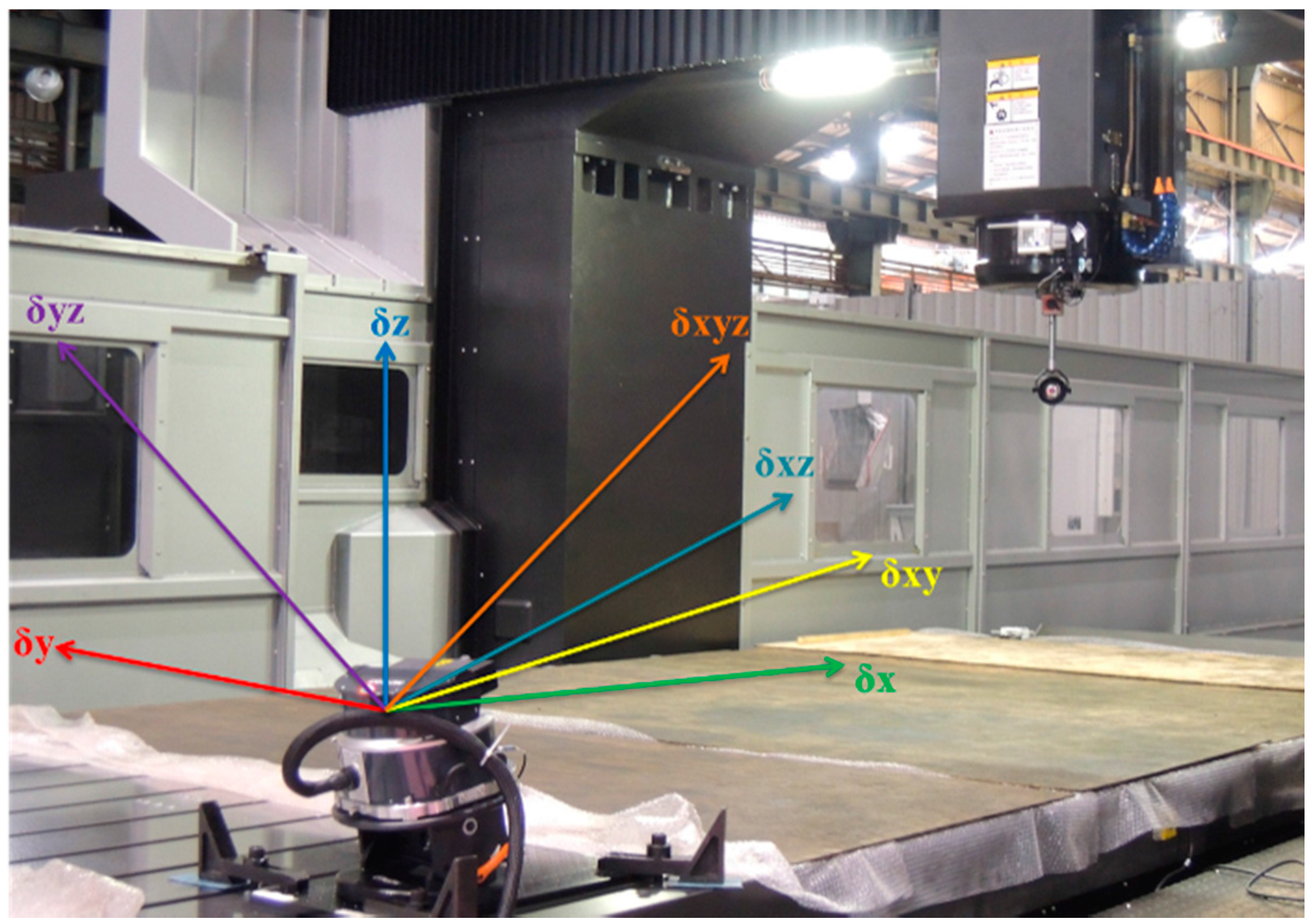
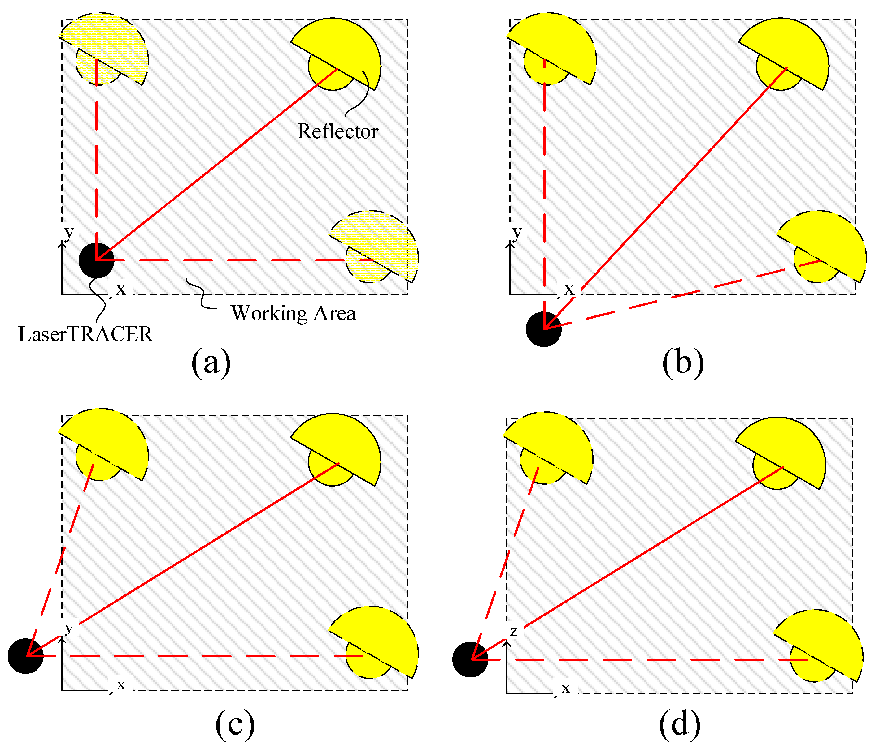
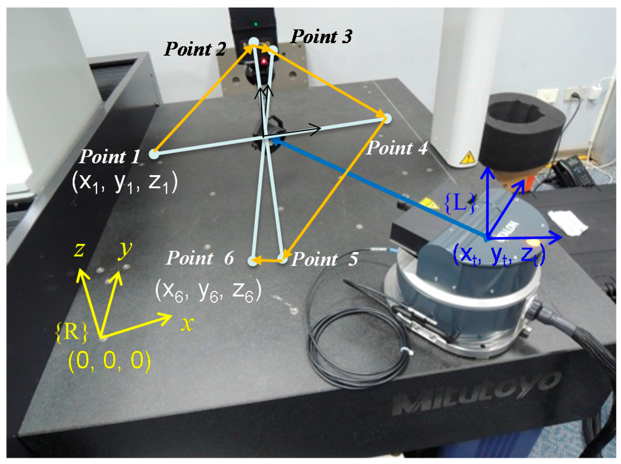
3.2. The Working Space

For machine tools calibration by means of LaserTRACER and multilateration (or time sharing), LaserTRACER can be placed out of the range of working area of the machine tool. To perform the seven lines testing, if the LaserTRACER is placed on the wrong position, some lines might be not measured. For instance, Figure 9 shows some situations in the x-y and x-z planes: (a) when the LaserTRACER placed inside of the working area, δx and δy can be performed; (b) when the LaserTRACER placed outside of the working area along y-axis, δx test cannot be carried out; (c) when the LaserTRACER placed outside of the working area along x-axis, δy test cannot be carried out; and (d) when the LaserTRACER placed outside of the working area along x-axis, δz test cannot be carried out. That is, the seven lines could be tested according to ISO 230-2 and -6 if and only if the LaserTRACER is placed inside of the working area of the machine tool in 3D space. Otherwise, some straight lines testing would be not performed.

3.3. LaserTRACER Coordinate Determination

The coordinate of the LaserTRACER on the machine tool is determined through six-point measurement, as seen in Figure 10, and the following Equations:
{ ( x 1 x t ) 2 + ( y 1 y t ) 2 + ( z 1 z t ) 2 = ( L 0 + Δ L 1 ) 2 ( x 2 x t ) 2 + ( y 2 y t ) 2 + ( z 2 z t ) 2 = ( L 0 + Δ L 2 ) 2 ( x 3 x t ) 2 + ( y 3 y t ) 2 + ( z 3 z t ) 2 = ( L 0 + Δ L 3 ) 2 ( x 4 x t ) 2 + ( y 4 y t ) 2 + ( z 4 z t ) 2 = ( L 0 + Δ L 4 ) 2 ( x 5 x t ) 2 + ( y 5 y t ) 2 + ( z 5 z t ) 2 = ( L 0 + Δ L 5 ) 2 ( x 6 x t ) 2 + ( y 6 y t ) 2 + ( z 6 z t ) 2 = ( L 0 + Δ L 6 ) 2 ,
Δ L i = L i L 0 , i = 1 , 2 , , 6 ,
where (xi yi zi) is the six stop points of the cat’s eye reflector, and these points are independent and should be given; (xt yt zt) is the coordinate of the LaserTRACER, which is to be determined; L0 is the initial distance from the LaserTRACER to the cat’s eye reflector, which is an unknown value; and ∆Li is the measured distance deviation from the LaserTRACER. Thus, the coordinate of the ATLI related to {R} can be determined by moving the reflector of six individual spatial points. If we define a symbol Ψ as below:
ψ = x t 2 + y t 2 + z t 2 L 0 2 ,
and then Equation (11) can be linearized and written in a matrix form as below:
[ x t y t z t L 0 ψ ] = [ 2 x 1 2 y 1 2 z 1 2 Δ L 1 1 2 x 2 2 y 2 2 z 2 2 Δ L 2 1 2 x 3 2 y 3 2 z 3 2 Δ L 3 1 2 x 4 2 y 4 2 z 4 2 Δ L 4 1 2 x 5 2 y 5 2 z 5 2 Δ L 5 1 2 x 6 2 y 6 2 z 6 2 Δ L 6 1 ] + [ x 1 2 + y 1 2 + z 1 2 Δ L 1 2 x 2 2 + y 2 2 + z 2 2 Δ L 2 2 x 3 2 + y 3 2 + z 3 2 Δ L 3 2 x 4 2 + y 4 2 + z 4 2 Δ L 4 2 x 5 2 + y 5 2 + z 5 2 Δ L 5 2 x 6 2 + y 6 2 + z 6 2 Δ L 6 2 ]
where the symbol “+” represents the pseudo inverse operator. Equation (14) can be simply described as following equation:
s = M + p ,

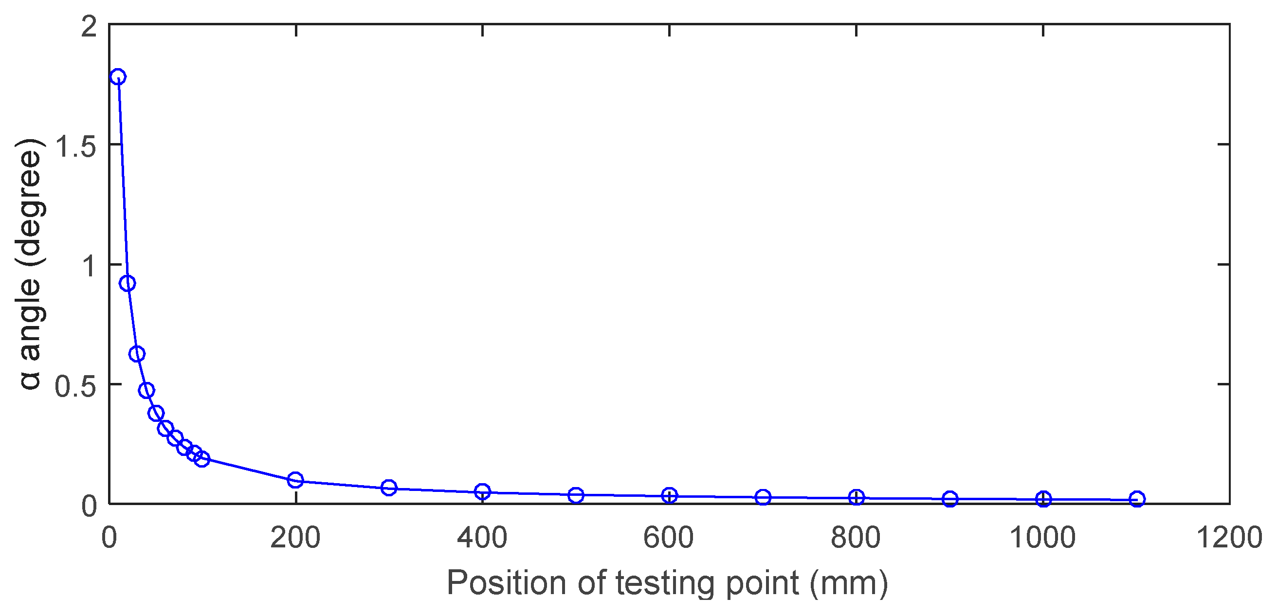
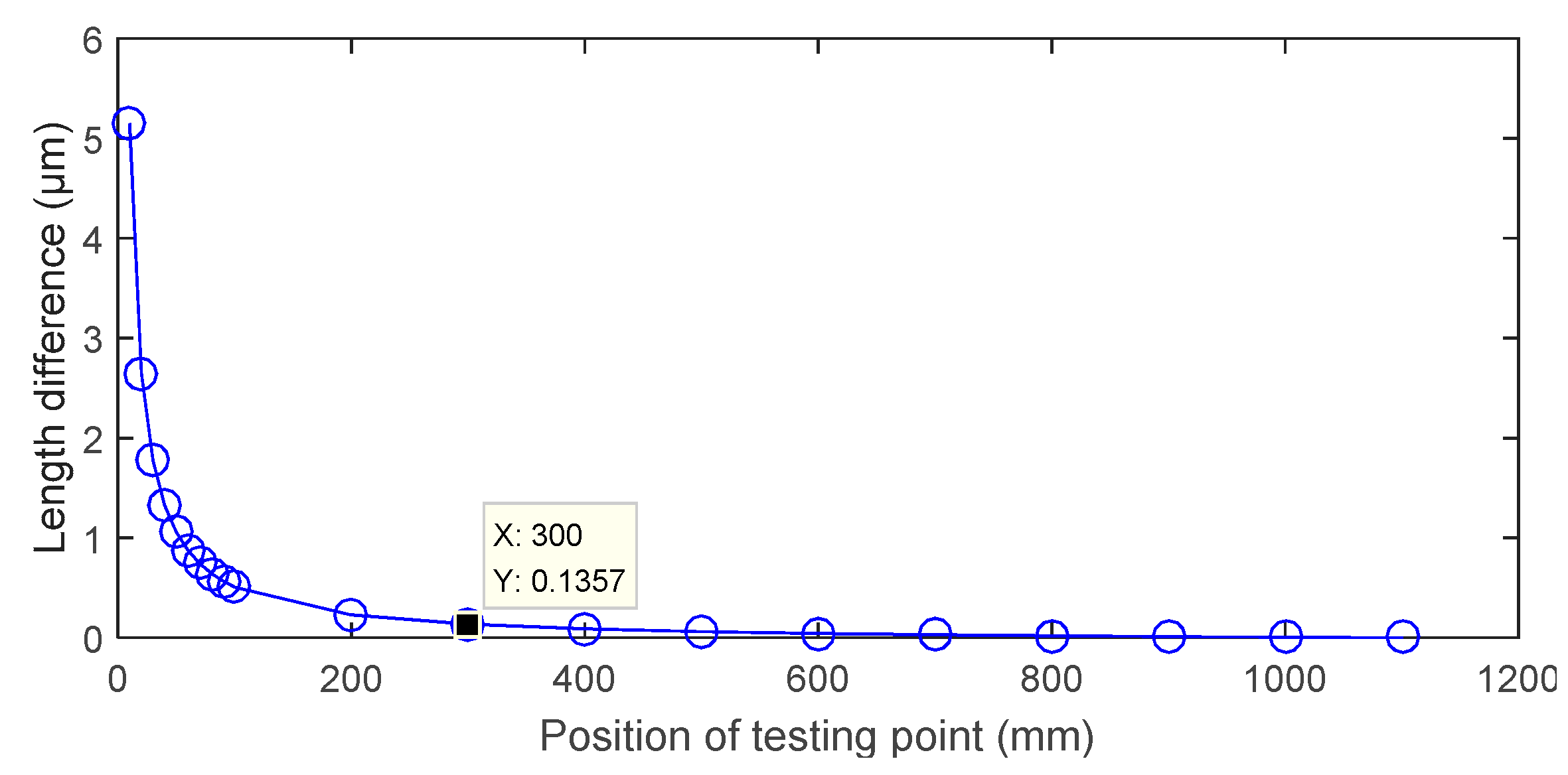
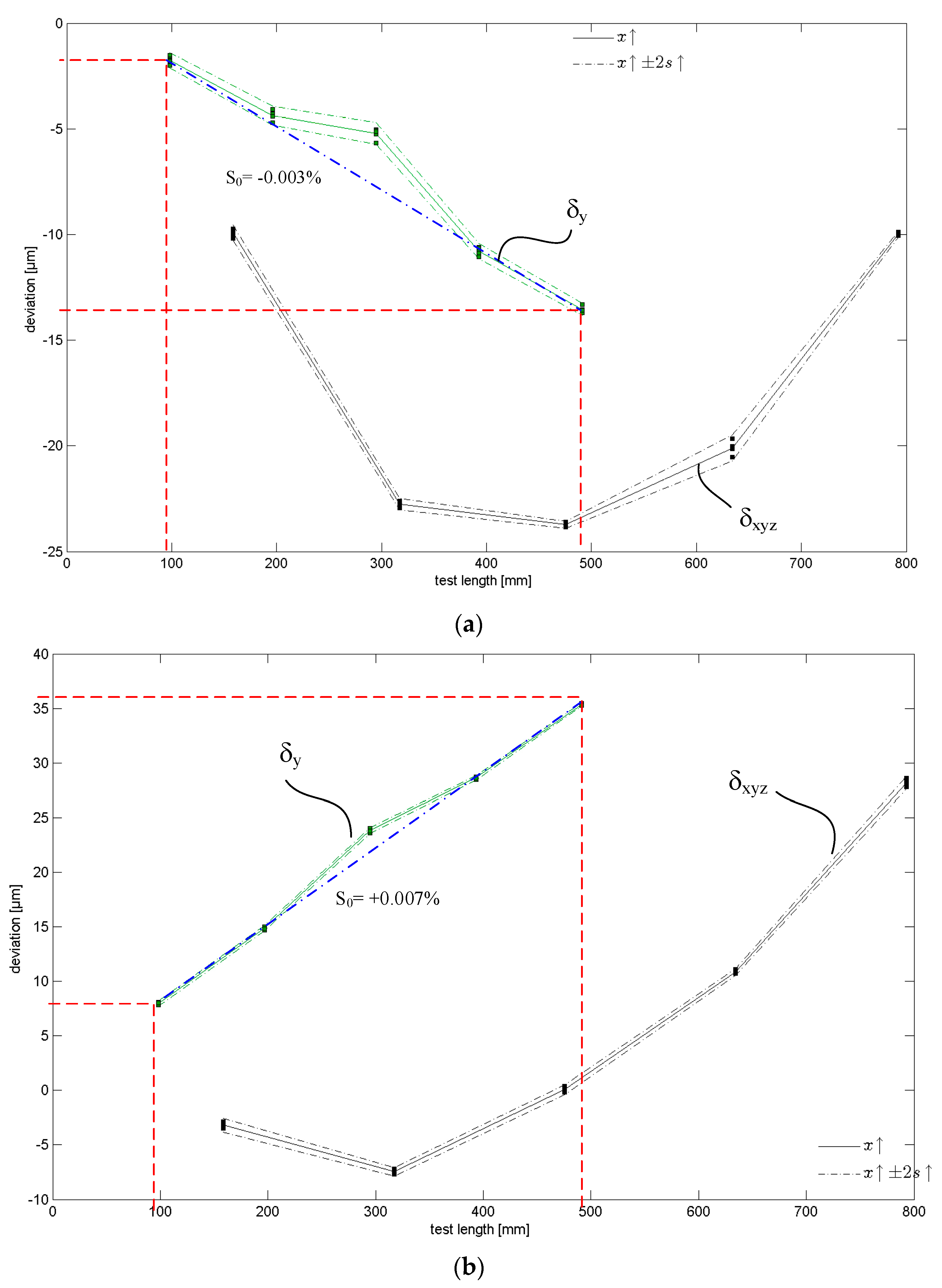
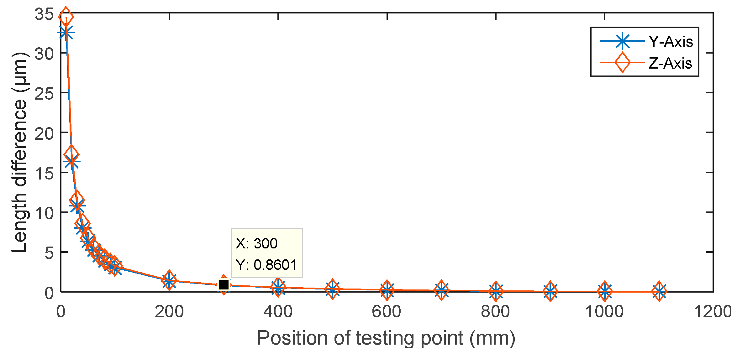
4. Effect of Positioning Accuracy

Effect of Length Difference

As previously mentioned, there are 21 terms of error motion in three-axis machine tool movement. The error motion causes low positioning accuracy. Assume the coordinate of the i-th target position (i.e., the stop point) is denoted (xi yi zi) and the actual position is denoted ( x ^ i y ^ i z ^ i ). The coordinate determined error between determined and the actual coordinates are as follows:
{ Δ x i = x i x ^ i Δ y i = y i y ^ i Δ z i = z i z ^ i
If the determined coordinate and actual position of the LaserTRACER are different, the α error is involved which is caused by misalignment. Please notice that the essence of misalignment of LaserTRACER is different to laser interferometer since the α error is a function of measurement length. As seen in Figure 5, Δx, Δy and Δz represent the determined LaserTRACER coordinate error in x-, y- and z-direction, respectively. Measuring length difference between the ideal path (represented d[k]) and the actual path (represented d ^ [ k ] ) for k-th target point of x-axis test is:
d [ k ] = d ^ [ k ] cos α [ k ] Δ x ,
α [ k ] = tan 1 ( Δ y 2 + Δ z 2 Δ x + d [ k ] ) ,
Δ d [ k ] = ( d ^ [ k ] d ^ [ n ] ) ( d [ k ] d [ n ] ) = d ^ [ n ] ( cos α [ n ] 1 ) + d ^ [ k ] ( 1 cos α [ k ] ) ,
in which k = 1, 2, …, n, n is the number of the target points, and d[n] and d ^ [ n ] are the distance from LaserTRACER to n-th target point (i.e., tn). Since ISO 230-2 and -6 results are calculated by the relative change in distance, and α changes convergence (far smaller than 1 degree) following measurement distance becoming far away from the origin point (as seen in Figure 11), which means the measurement length difference also becomes small, measurement length difference can be computed by Equation (19). Here, we can see that the effect of ∆x has been eliminated. Combined with Equations (17) and (18), Equation (19) can be rewritten as:
Δ d x [ k ] = d ^ x [ n ] [ Δ x + d x [ n ] ( Δ x + d x [ n ] ) 2 + Δ y 2 + Δ z 2 1 ] d ^ x [ k ] [ 1 Δ x + d x [ k ] ( Δ x + d x [ k ] ) 2 + Δ y 2 + Δ z 2 ]
The simulation results for length difference in different measuring lengths are shown in Figure 12 and Figure 13. In this simulation, we let Δx, Δy and Δz, respectively, be 0.7978, 0.2715 and 0.1965 mm (these values have no any meaning and are not very important, we just use these values to perform the evaluation), in which the measurement length differences in y- and z-axis are computed by:
Δ d y [ k ] = d ^ y [ n ] [ Δ y + d y [ n ] Δ x 2 + ( Δ y + d y [ n ] ) 2 + Δ z 2 1 ] d ^ y [ k ] [ 1 Δ y + d y [ k ] Δ x 2 + ( Δ y + d y [ k ] ) 2 + Δ z 2 ]
Thus, the total measurement length difference is:
Δ d z [ k ] = d ^ z [ n ] [ Δ z + d z [ n ] Δ x 2 + Δ y 2 + ( Δ z + d z [ n ] ) 2 1 ] d ^ z [ k ] [ 1 Δ z + d z [ k ] Δ x 2 + Δ y 2 + ( Δ z + d z [ k ] ) 2 ]
Δ d [ k ] = Δ d x 2 [ k ] + Δ d y 2 [ k ] + Δ d z 2 [ k ]
In Figure 12 and Figure 13, we can see that the measurement length difference could be ignored when the measurement length is farther than 300 mm. In this simulation, the distances between the target points and the reference sphere of LaserTRACER are 10, 20, …, 90, 100, 200, 300, …, 1100 mm (these lengths are absolute distance from the reference sphere of LaserTRACER to the target points). After setting the lengths and Δx, Δy and Δz, the measurement line angle α can be computed. Therefore, according to Equations (20)–(22), the length difference can be computed. The simulation result is similar to the result that descripted in ISO 230-2. The total measurement length difference becomes smaller with decreasing Δx, Δy and Δz. Thus, our inference in this section is that: (1) the α error due to misalignment can be ignored for testing the positioning performance of a high accuracy machine tool because the coordinate determined error of the LaserTRACER is very small; and (2) measurement length difference due to misalignment can be ignored when the measurement length is farther than 300 mm for a larger coordinate determined error.

5. Conclusions

To test the positioning accuracy and repeatability of a machine tool according to ISO 230-2 and -6, four steps should be executed when using a LaserTRACER as the measurement instrument: (1) setup; (2) determining the coordinate related to the machine tool; (3) performing ISO 230-2 and -6 tests; and (4) testing report generation. In step 2, since the coordinate of the LaserTRACER is determined by six independent points, positioning accuracy of the machine tool causes LaserTRACER coordinate determined error. To evaluate the influence of positioning accuracy of the machine tool with respect to the ISO 230-2 and -6 test results, three experiments were performed, coordinate offset simulation, proportional error simulation and ISO 230-2 and -6 tests with proportional error. Some conclusions are made in this study from observing the experiment results:
(1)
Positioning accuracy of the machine tool causes LaserTRACER coordinate determined error;
(2)
The coordinate determined error because of coordinate offset error exactly equals the given value;
(3)
The coordinate offset error does not affect the ISO 230-2 and -6 test results;
(4)
Although the proportional error, in an example simulation of the ball screw lead difference, causes the coordinate determined error, it does not affect the ISO 230-2 and -6 test results;
(5)
Positioning accuracy and repeatability can be achieved through ISO 230-2 and -6 tests using a LaserTRACER.

Acknowledgments

This study is supported by BIPM (Bureau of Standards, Metrology & Inspection), Taiwan (F407EQ2100).

Author Contributions

Hau-Wei Lee is the project leader who designs the experiments and performs simulation, write the manuscript, derives the equations and is the corresponding author; Jr-Rung Chen performs experiments, equations checking, manuscript proofreading and manuscript revising; Shan-Peng Pan and Hua-Chung Liou help for performing experiments and results checking; and Po-Er Hsu help for manuscript proofreading/revising and the simulation results checking.

Conflicts of Interest

The authors declare no conflict of interest.

References

  1. Zhang, G.; Ouyang, R.; Lu, B.; Hocken, R.; Veale, R.; Donmez, A. A Displacement method for machine geometry calibration. CIRP Ann. Manuf. Technol. 1988, 37, 515–518. [Google Scholar] [CrossRef]
  2. International Organization for Standardization. 230: Test code for machine tools. In Part 6: Determination of Positioning Accuracy on Body and Face Diagonals (Diagonal Displacement Tests); ISO: Geneva, Switzerland, 2002. [Google Scholar]
  3. International Organization for Standardization. 230: Test code for machine tools. In Part 2: Determination of Accuracy and Repeatability of Positioning Numerically Controlled Axes; ISO: Geneva, Switzerland, 2012. [Google Scholar]
  4. Liu, C.H.; Jywe, W.Y.; Hsu, C.C.; Hsu, T.H. Development of a laser-based high-precision six-degrees-of-freedom motion errors measuring system for linear stage. Rev. Sci. Instrum. 2005, 76. [Google Scholar] [CrossRef]
  5. Lau, K.; Hocken, R.J.; Haight, W.C. Automatic laser tracking interferometer system for robot metrology. Precis. Eng. 1986, 8, 3–8. [Google Scholar] [CrossRef]
  6. Muralikrishnan, B.; Phillips, S.; Sawyer, D. Laser trackers for large-scale dimensional metrology: A review. Precis. Eng. 2016, 44, 13–28. [Google Scholar] [CrossRef]
  7. Physikalisch-Technische Bundesanstalt. Nachführbares Interferometer Mit Mechanisch und Thermisch Entkoppeltem, Metrologischem Referenzelement (TRACER); PTB: Braunschweig, Germany, 2004. [Google Scholar]
  8. Hughes, E.B. Tracking System. US Patent 6147748, 14 November 2000. [Google Scholar]
  9. Hughes, E.B.; Wilson, A.; Peggs, G.N. Design of a high-accuracy CMM based on multi-lateration techniques. CIRP Ann. Manuf. Technol. 2000, 49, 391–394. [Google Scholar] [CrossRef]
  10. Bala, M.; Lee, V.; Blackburn, C.; Sawyer, D.; Phillips, S.; Ren, W.; Hughes, B. Assessing ranging errors as a function of azimuth in laser trackers and tracers. Meas. Sci. Technol. 2013, 24. [Google Scholar] [CrossRef]
  11. Toshiyuki, T.; Goto, M.; Kurosawa, T.; Tanimura, Y.; Koseki, Y. The first measurement of a three-dimensional coordinate by use of a laser tracking interferometer system based on trilateration. Meas. Sci. Technol. 1998, 9, 38–41. [Google Scholar]
  12. Wendt, K.; Franke, M.; Härtig, F. Measuring large 3D structures using four portable tracking laser interferometers. Measurement 2012, 45, 2339–2345. [Google Scholar] [CrossRef]
  13. Wang, J.; Guo, J.; Zhou, B.; Xiao, J. The detection of rotary axis of NC machine tool based on multi-station and time-sharing measurement. Measurement 2012, 45, 1713–1722. [Google Scholar] [CrossRef]
  14. Lee, H.W.; Liu, C.H.; Chu, K.T.; Tseng, H.C. Kinect who’s coming—Applying kinect to human body height measurement to improve character recognition performance. Smart Sci. 2015, 3, 117–121. [Google Scholar]
  15. Lee, H.W.; Chen, C.L. Applying dual-laser spot positions measurement technology on a two-dimensional tracking measurement system. Meas. Sci. Technol. 2009, 20. [Google Scholar] [CrossRef]
  16. Lee, H.W.; Chen, C.L.; Liu, C.H. Development of an optical three-dimensional laser tracker using dual modulated laser diodes and a signal detector. Rev. Sci. Instrum. 2011, 82. [Google Scholar] [CrossRef] [PubMed]
  17. Lee, H.W.; Liu, C.H. Development of a steel ball center alignment device based on Michelson interference concept. Rev. Sci. Instrum. 2014, 85. [Google Scholar] [CrossRef] [PubMed]
  18. Bundesrepublik Deutschland, vertr. d.d.; Bundesministerium für Wirtschaft und Arbeit, dieses vertr. d.d.; Präsidenten der Physikalisch-Technischen Bundesanstalt. Laser Interferometer for Spacing Measurement Has Reference Sphere Positioned on Post and Base Plate Made of Thermally Invariant Material. German Patent DE202004007647, 16 September 2004. (In German)[Google Scholar]
  19. Ouyang, J.F.; Liu, W.L.; Yan, Y.G.; Sun, D.X. Angular error calibration of laser tracker system. Proc. SPIE Adv. Laser Technol. 2005, 6344. [Google Scholar] [CrossRef]
  20. Linares, J.M.; Chaves-Jacob, J.; Schwenke, H.; Longstaff, A.; Fletcher, S.; Flore, J.; Uhlmann, E.; Wintering, J. Impact of measurement procedure when error mapping and compensating a small CNC machine using a multilateration laser interferometer. Precis. Eng. 2014, 38, 578–588. [Google Scholar] [CrossRef]
  21. Zhang, G.; Veale, R.; Charlton, T.; Borchardt, B.; Hocken, R. Error compensation of coordinate measuring machines. CIRP Ann. Manuf. Technol. 1985, 34, 445–448. [Google Scholar] [CrossRef]
  22. Wang, J.; Guo, J.; Zhang, G.; Guo, B.; Wang, H. The technical method of geometric error measurement for multi-axis NC machine tool by laser tracker. Meas. Sci. Technol. 2012, 23, 45003–45013. [Google Scholar] [CrossRef]
  23. Schwenke, H.; Franke, M.; Hannaford, J.; Kunzmann, H. Error mapping of CMMs and machine tools by a single tracking interferometer. CIRP Ann. Manuf. Technol. 2005, 54, 475–478. [Google Scholar] [CrossRef]
  24. Schwenke, H.; Schmitt, R.; Jatzkowski, P.; Warmann, C. On-the-fly calibration of linear and rotary axes of machine tools and CMMs using a tracking interferometer. CIRP Ann. Manuf. Technol. 2009, 58, 477–480. [Google Scholar] [CrossRef]
  25. Ezedine, F.; Linares, J.M.; Sprauel, J.M.; Chaves-Jacob, J. Smart sequential multilateration measurement strategy for volumetric error compensation of an extra-small machine tool. Precis. Eng. 2016, 43, 178–186. [Google Scholar] [CrossRef]
Figure 1. Illustration of the basic structure of LaserTRACER in which the reflected light is focused on the sphere center by the lens. (Note: BS = Beam Splitter; PBS = Polarizing Beam Splitter).
Applsci 06 00105 g001
Figure 2. Illustration for optical path difference because of run-out error of bearing: (a) Laser Tracker uses a mirror to reflect the laser beam; and (b) LaserTRACER uses a steel sphere to reflect the laser beam.
Applsci 06 00105 g002
Figure 3. Multilateration requires more than four LaserTRACERs for target spatial position computing, where Point 1 to Point 4 represent the target points 1 to 4, LT1 to LT4 represent the position of the LaserTRACER No. 1 to No. 4.
Applsci 06 00105 g003
Figure 4. Illustration of the simulation for machine tool moved with positioning error: (a) coordinate offset; and (b) proportional error. (Note: vector o = [ o x o y o z ] T represents the coordinate offset vector; t i represents the i-th target point; k represents the proportional value; and t i represents the i-th target point with coordinate offset or proportional error).
Applsci 06 00105 g004
Figure 5. If the actual and determined positions of the ATLI are different, the measurement difference becomes smaller over the measurement distance. In the figure, t0 to tn represent the number of target point to be tested.
Applsci 06 00105 g005
Figure 6. Experiment results for x-axis and xyz diagonal line test. (a) Original test result; (b) test result after proportional error given.
Applsci 06 00105 g006
Figure 7. ISO 230-2 and ISO 230-6 test procedure for testing the machine linear axes positioning accuracy and repeatability.
Applsci 06 00105 g007
Figure 8. Illustration of the positioning accuracy and repeatability test according to ISO 230-2 and-6 for machine tools.
Applsci 06 00105 g008
Figure 9. The ATLI must be placed inside the working area of machine tools: (a) the ATLI placed inside the working area (xy plane view); (b) when ATLI placed outside of the working area in y-direction (xy plane view); (c) the ATLI placed outside of the working area in x-direction (xy plane view); and (d) the ATLI placed outside of the working area in x-direction (xz plane view).
Applsci 06 00105 g009
Figure 10. The coordinate of the LaserTRACER located on the machine is determined by six-point measurement, in which {R} represents the reference coordinate system (i.e., the reference point); {L} represents the coordinate system of the LaserTRACER; and {T} represents the coordinate system of the cat’s eye reflector.
Applsci 06 00105 g010
Figure 11. The deviation of the α angle following measurement distance changes when Δx, Δy and Δz are 0.7978, 0.2715 and 0.1965 mm, respectively.
Applsci 06 00105 g011
Figure 12. Simulation result of measurement length difference (x-axis).
Applsci 06 00105 g012
Figure 13. Simulation result of measurement length difference (y- and z-axis).
Applsci 06 00105 g013
Table 1. Comparison of measurement uncertainty for different auto-tracking laser interferometers (ATLIs) (the value is from manufacturer catalogs). (Note: ADM = Absolute Distance Measurement; IFM = Interferometer; AIFM = Absolute Distance Measurement + Interferometer).
ModeWorking Range (m)Angular AccuracyDistance Accuracy
ADMIFM
Leica AT96040/160±15 μm + 6 μm/m±0.5 μm/m (AIFM)
Leica AT930160±15 μm + 6 μm/m
Leica AT90150/160±15 μm + 6 μm/m±10 μm±0.4 μm + 0.3 μm/m
Leica AT402320±15 μm + 6 μm/m±10 μm-
Leica AT401320±15 μm + 6 μm/m±10 μm-
Leica LTD60040±25 μm±25 μm±10 μm ±0.5 μm/m
API Tracker330/80/> 1203.5 μm/m±15 μmwhthin ±0.5 μm/m
API Radian40/100/> 1603.5 μm/m±10 μmwhthin ±0.5 μm/m
API Omnitrac2160/2003.5 μm/m±15 μm-
FARO ION30/40/5520 μm + 5 μm/m16 μm + 0.8 μm/m4 μm + 0.8 μm/m
FARO Vantage30/60/8020 μm + 5 μm/m16 μm + 0.8 μm/m-
Etalon LaserTRACER0.2–20--0.2 μm + 0.3 μm/m (Measuring Uncertainty, k = 2)
Table 2. Experiment results of the coordinate offset simulation. (Unit: mm).
Offset ValueCoordinate Difference
xyz
x-axis, +1 mm−1.000.000.00
x-axis, −1 mm1.000.000.00
y-axis, +1 mm0.00−1.000.00
y-axis, −1 mm0.001.010.01
z-axis, +1 mm0.000.00−0.99
z-axis, −1 mm0.010.001.00
x- and y-axis, +1 mm−1.00−1.000.01
x- and y-axis, −1 mm1.001.000.01
x- and z-axis, +1 mm−1.000.00−0.99
x- and z-axis, −1 mm1.000.001.01
y- and z-axis, +1 mm0.01−1.00−1.00
y- and z-axis, −1 mm0.001.001.01
Table 3. Experiment results of proportional error simulation. (Unit: mm).
Proportional ValueCoordinate Difference
xyz
x-axis, 1.010.06−0.10−0.01
x-axis, 0.99−0.060.100.02
y-axis, 1.010.15−0.25−0.03
y-axis, 0.99−0.140.240.04
z-axis, 1.010.01−0.01−0.04
z-axis, 0.99−0.020.030.40
x- and y-axis, 1.010.21−0.35−0.04
x- and y-axis, 0.99−0.200.350.05
x- and z-axis, 1.010.06−0.11−0.05
x- and z-axis, 0.99−0.060.110.06
y- and z-axis, 1.010.15−0.25−0.07
y- and z-axis, 0.99−0.140.250.08

