
Study of a Microfluidic Chip Integrating Single Cell Trap and 3D Stable Rotation Manipulation


Abstract
:
1. Introduction
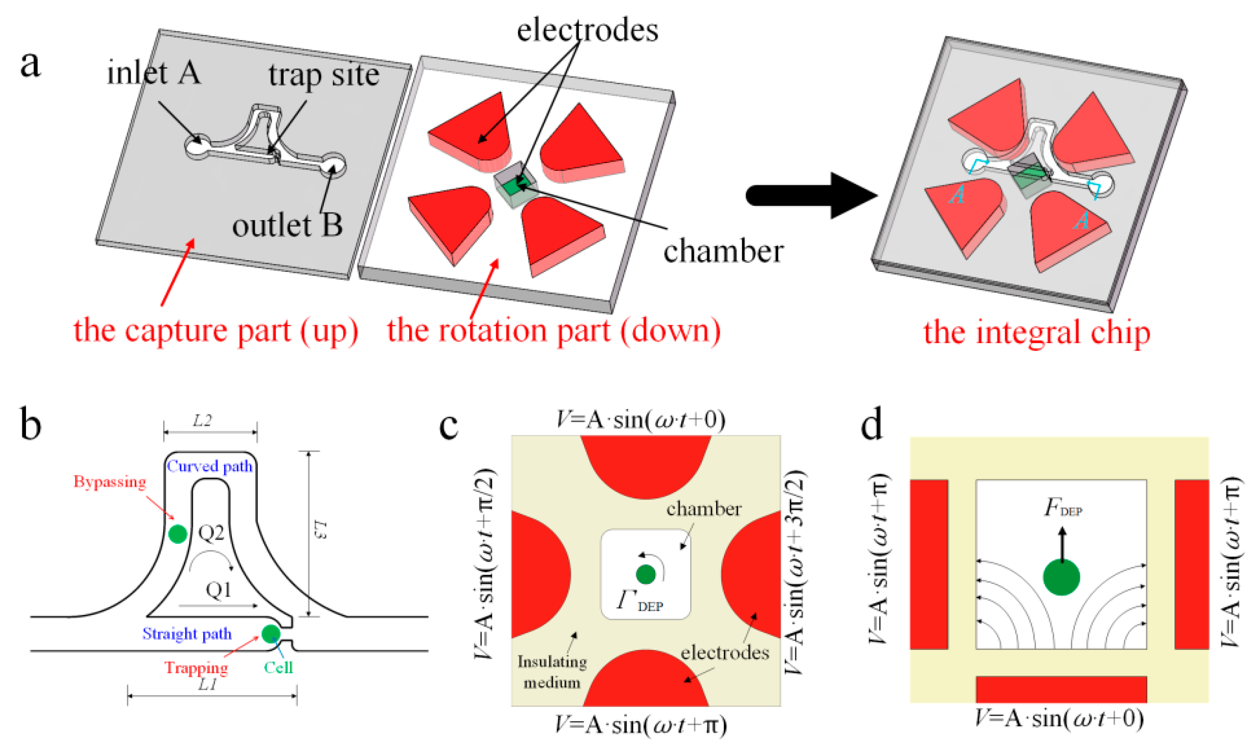
2. Chip Design
3. Simulation and Results
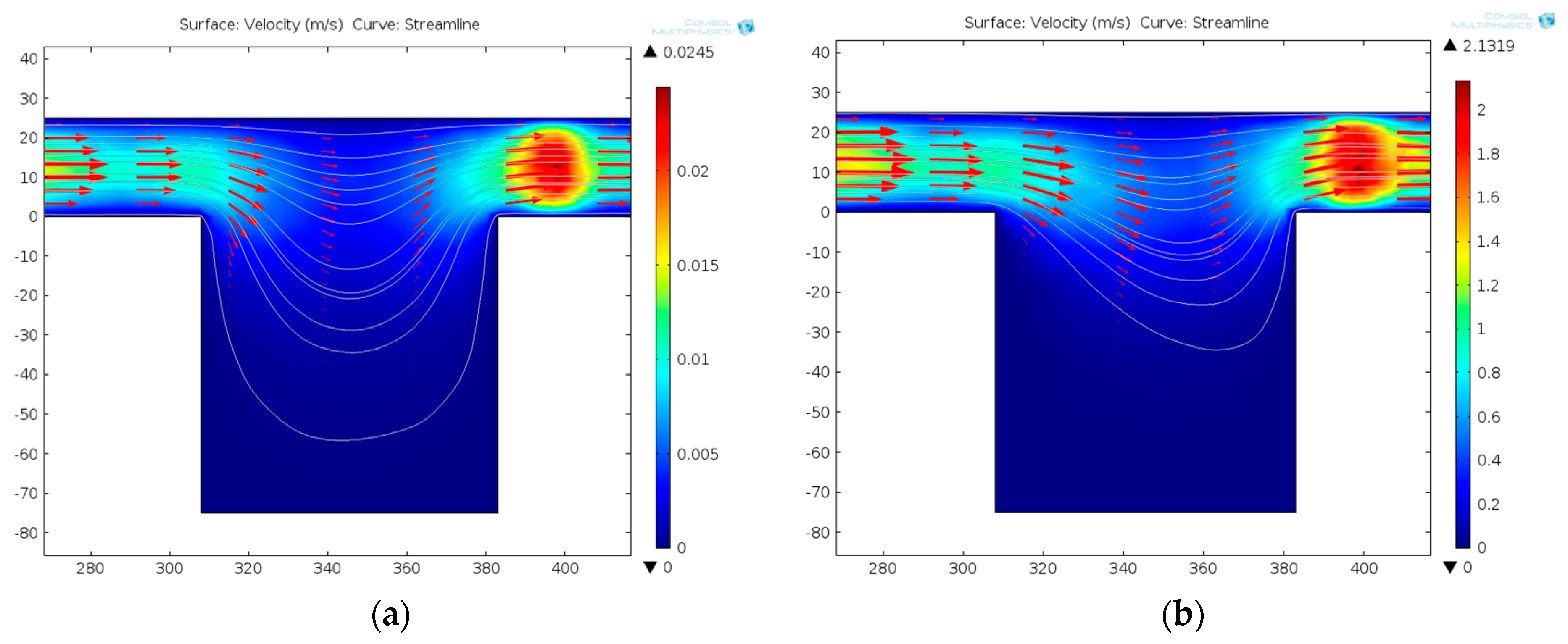
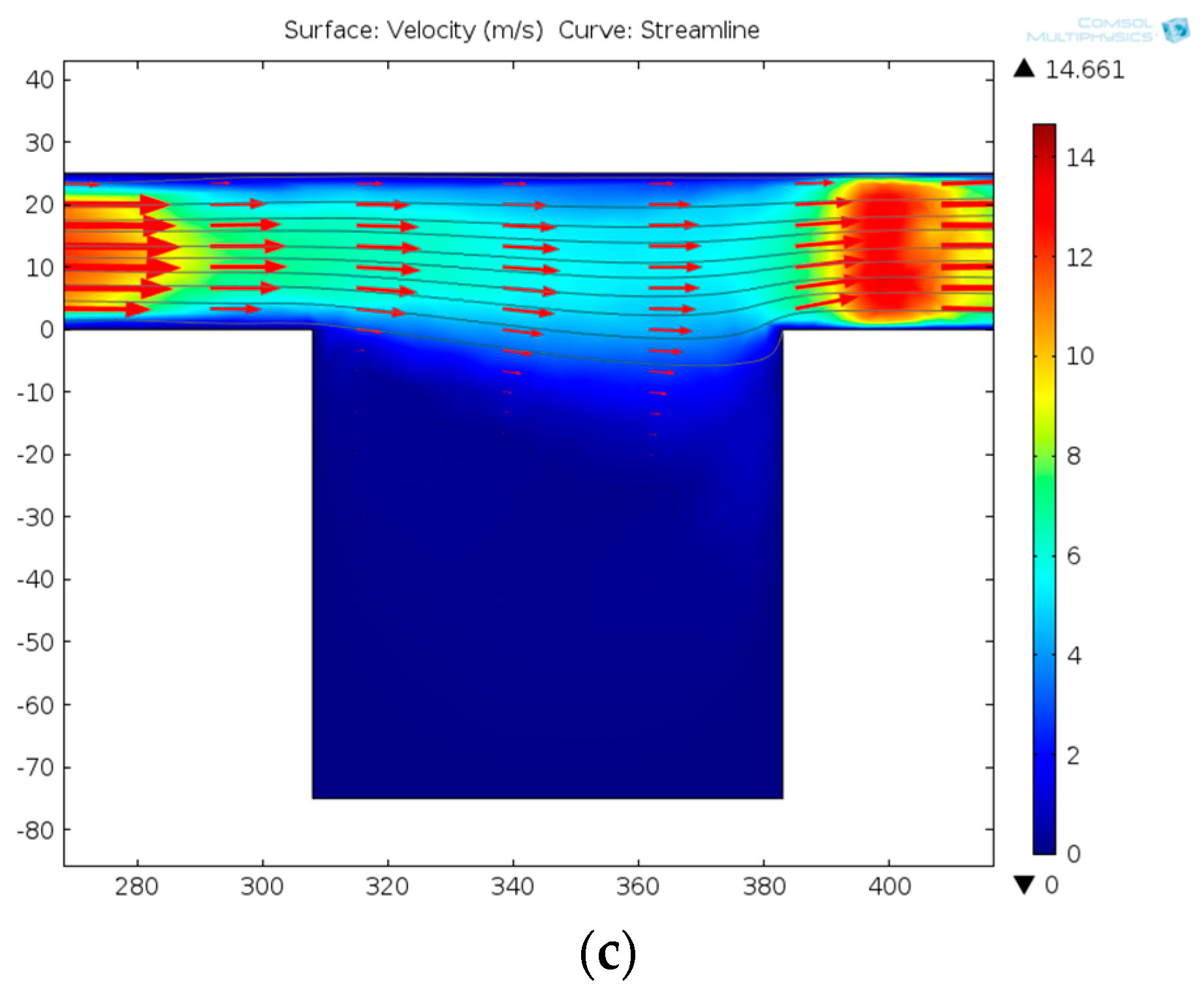
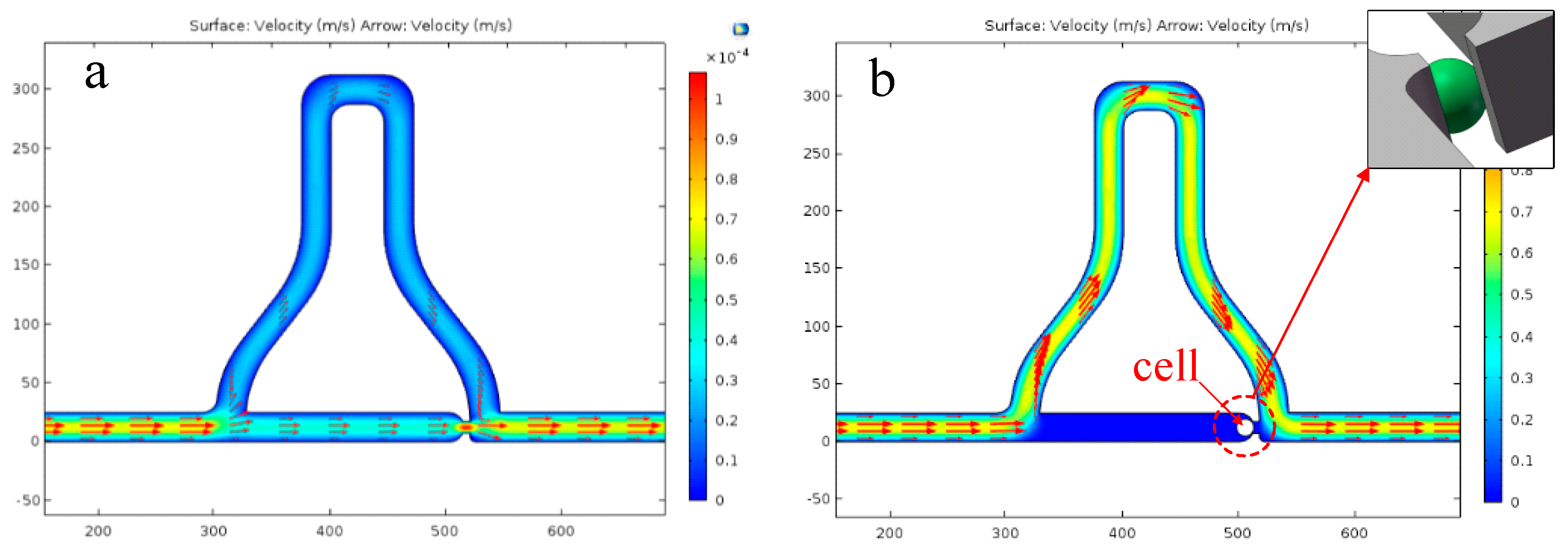
3.1. The Placement of a Single Cell in the Rotation Chamber
3.2. Making Cell Have Stable 3D Rotations
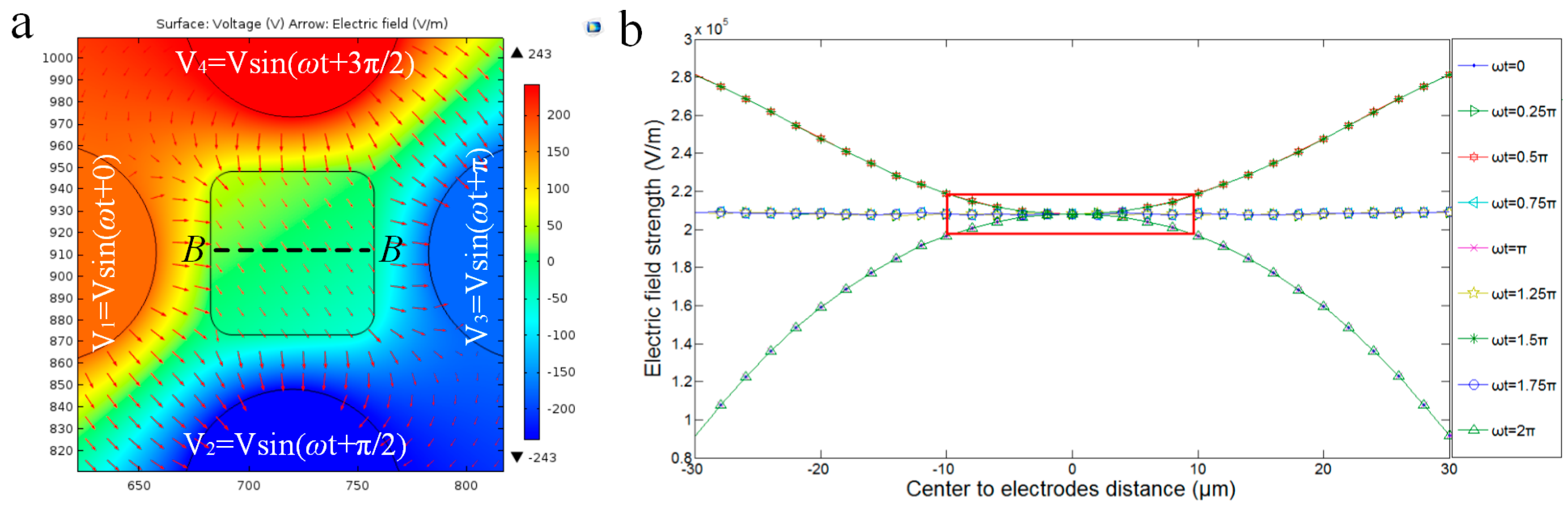
3.2.1. Dynamic Central Position Adjustment for a Self-Adapted Cell
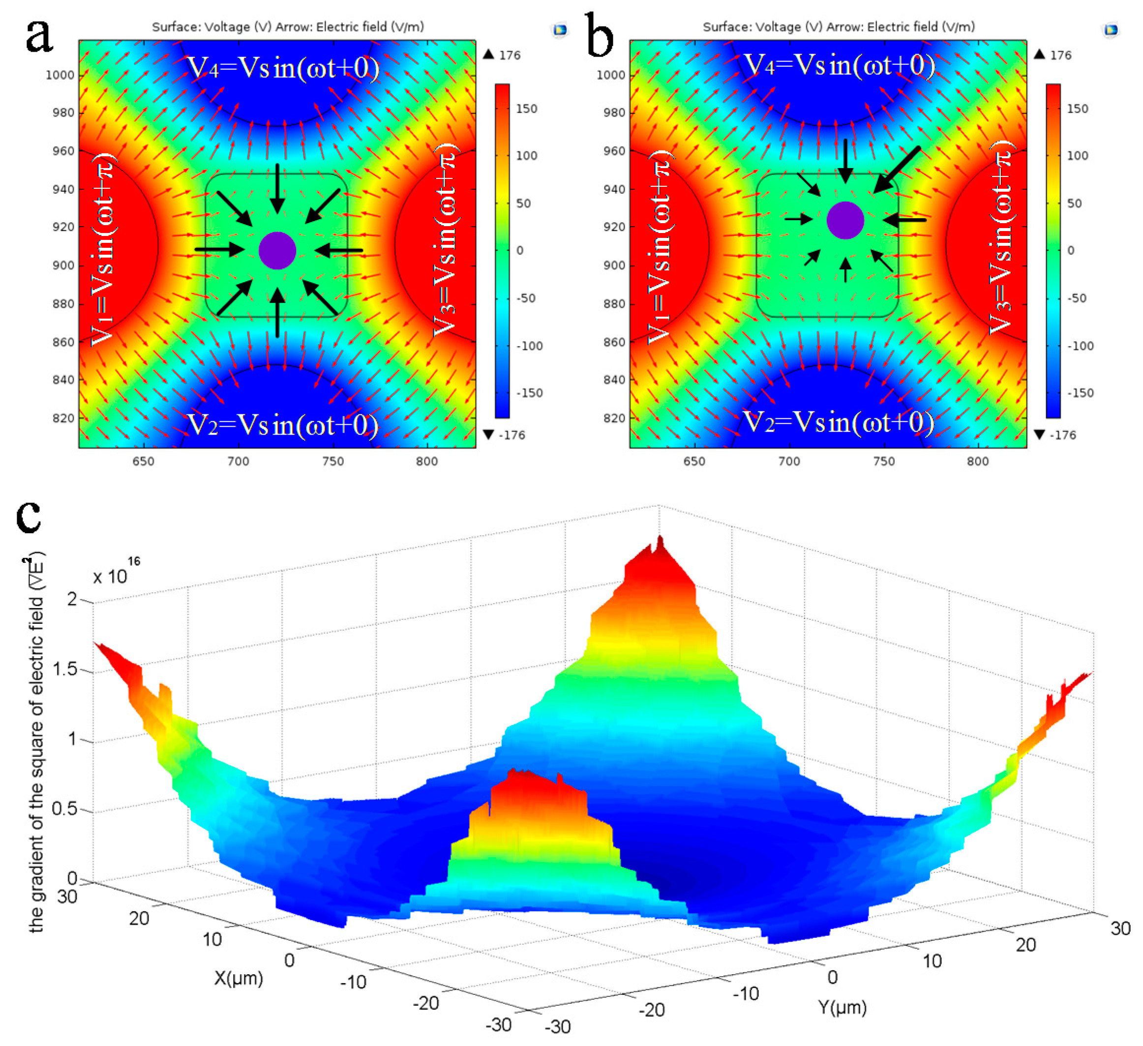
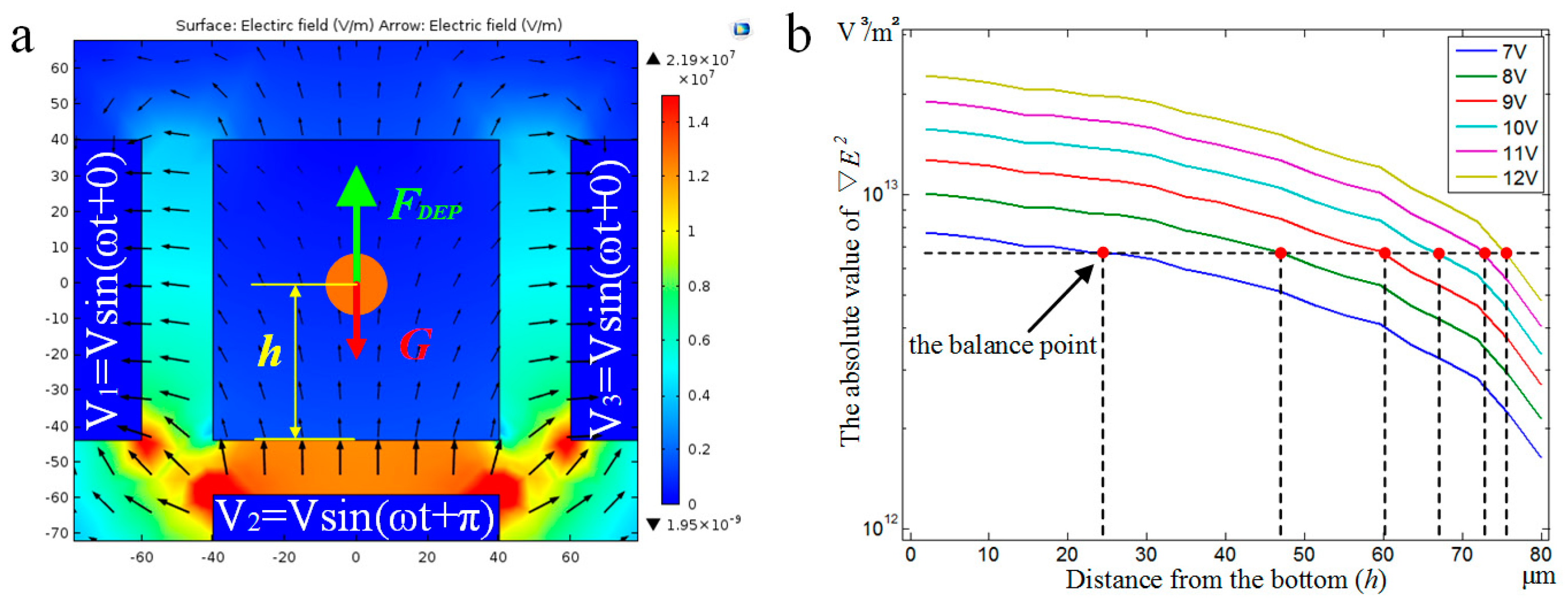
3.2.2. DEP Force Analysis for Balancing Gravity
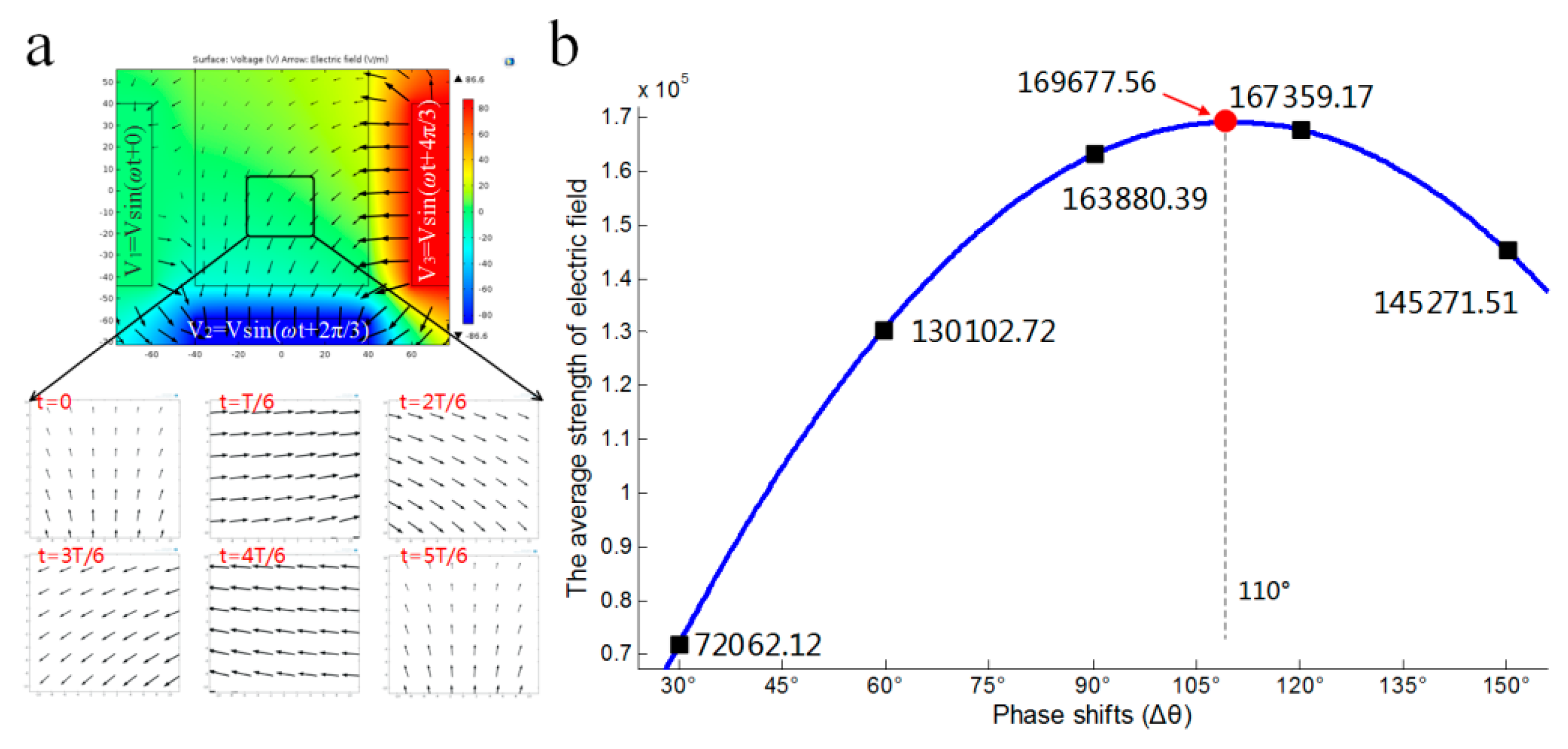
3.2.3. Electric Field Analysis for Pitch Rotation of Cell
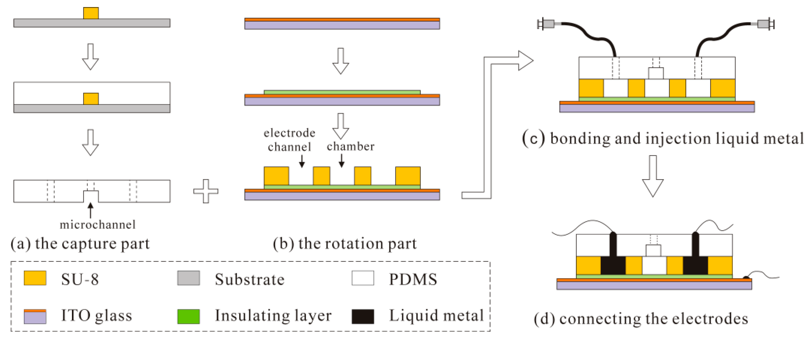
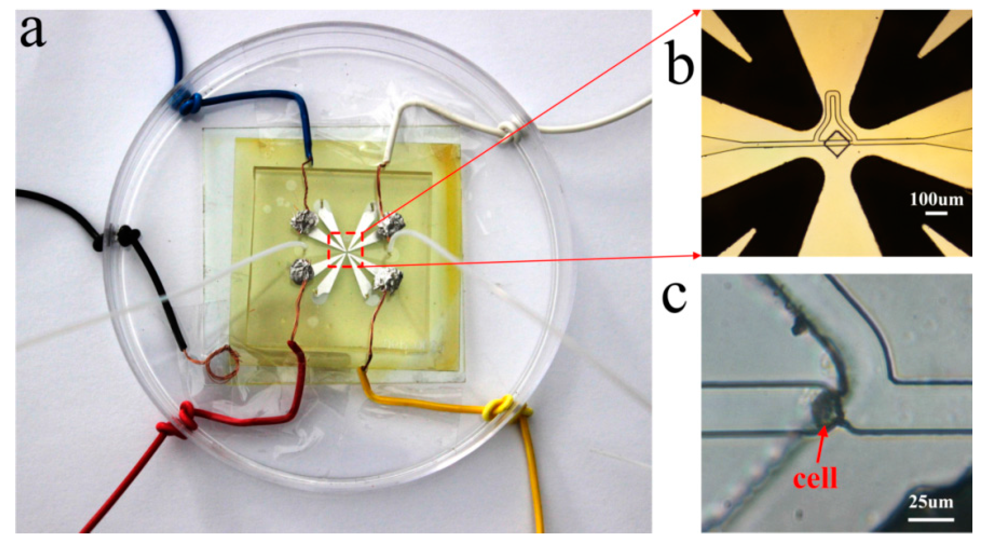
4. Fabrication of the Device
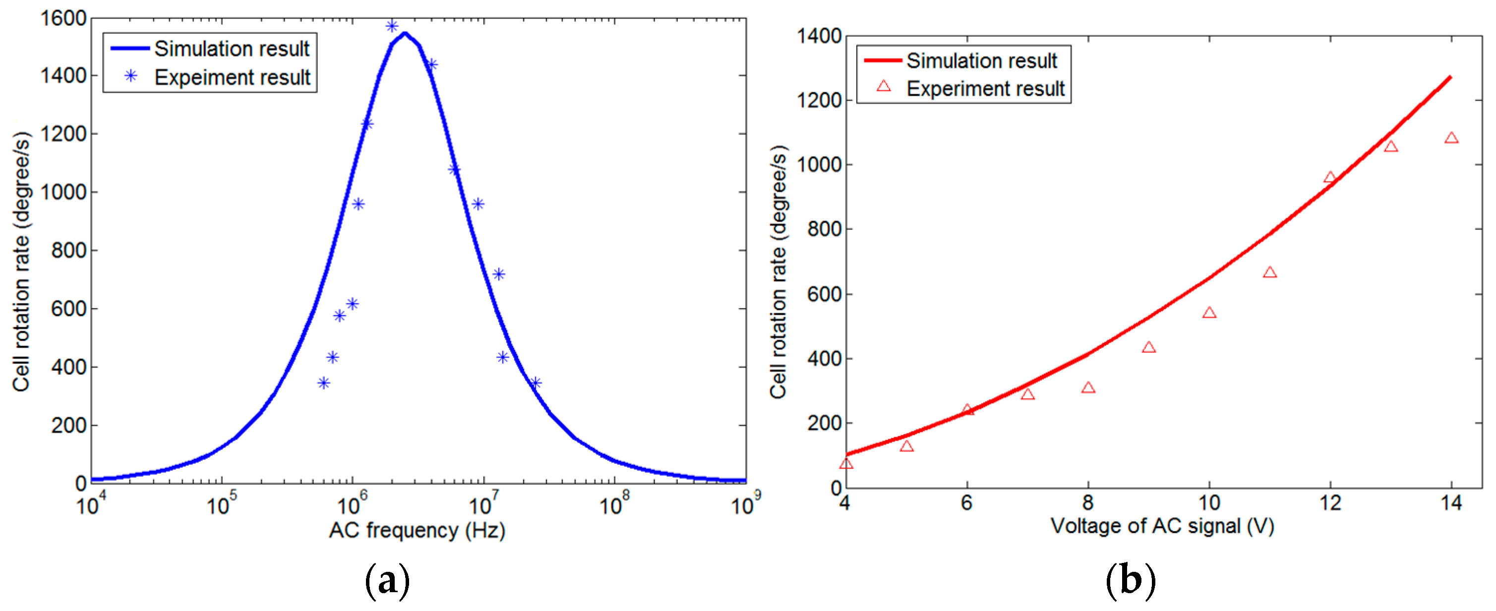
5. Experimental Demonstration and Discussion
- Driving the solution into the capture part, and cells prefer to go through the straight line.
- One cell is captured at the trap site and the following cells flow into the curved path bypass though the straight path.
- Back and low rate flow drives the cell into the chamber.
- Apply AC signals to make the cell self-adapt to the central position and suspend.
- Apply another signals configuration to make the cell perform a 3D rotation.
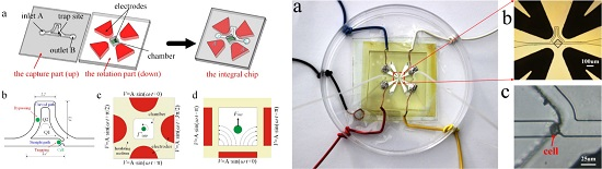
- Levitate and recycle the cell. Figure 9c is a picture of one single cell captured at the trap site.
6. Conclusions
Acknowledgments
Author Contributions
Conflicts of Interest
References
- Soffe, R.; Tang, S.; Baratchi, S.; Nahavandi, S.; Nasabi, M.; Cooper, J.M.; Mitchell, A.; Khoshmanesh, K. Controlled rotation and vibration of patterned cell clusters using dielectrophoresis. Anal. Chem. 2015, 87, 2389–2395. [Google Scholar] [CrossRef] [PubMed]
- Jo, Y.; Shen, F.; Hahn, Y.; Park, J.; Park, J. Magnetophoretic sorting of single Cell-Containing microdroplets. Micromachines 2016, 7, 56–65. [Google Scholar] [CrossRef]
- Gascoyne, P.; Shim, S. Isolation of circulating tumor cells by dielectrophoresis. Cancers 2014, 6, 545–579. [Google Scholar] [CrossRef] [PubMed]
- Rao, L.; Cai, B.; Wang, J.; Meng, Q.; Ma, C.; He, Z.; Xu, J.; Huang, Q.; Li, S.; Cen, Y.; et al. A microfluidic electrostatic separator based on pre-charged droplets. Sens. Actuators B Chem. 2015, 210, 328–335. [Google Scholar] [CrossRef]
- Yasukawa, T.; Yamada, J.; Shiku, H.; Mizutani, F.; Matsue, T. Positioning of cells flowing in a fluidic channel by negative dielectrophoresis. Sens. Actuators B Chem. 2013, 186, 9–16. [Google Scholar] [CrossRef]
- Han, S.; Joo, Y.; Han, K. An electrorotation technique for measuring the dielectric properties of cells with simultaneous use of negative quadrupolar dielectrophoresis and electrorotation. Analyst 2013, 138, 1529–1537. [Google Scholar] [CrossRef] [PubMed]
- Liang, Y.L.; Huang, Y.P.; Lu, Y.S.; Hou, M.T.; Yeh, J.A. Cell rotation using optoelectronic tweezers. Biomicrofluidics 2010, 4, 043003. [Google Scholar] [CrossRef] [PubMed]
- Cen, E.G.; Dalton, C.; Li, Y.; Adamia, S.; Pilarski, L.M.; Kaler, K.V.I.S. A combined dielectrophoresis, traveling wave dielectrophoresis and electrorotation microchip for the manipulation and characterization of human malignant cells. J. Microbiol. Meth. 2004, 58, 387–401. [Google Scholar] [CrossRef] [PubMed]
- Hosseini, S.M.; Hajian, M.; Moulavi, F.; Asgari, V.; Forouzanfar, M.; Nasr-Esfahani, M.H. Cloned sheep blastocysts derived from oocytes enucleated manually using a pulled pasteur pipette. Cell. Reprogr. 2013, 15, 15–23. [Google Scholar]
- Hosseini, S.M.; Moulavi, F.; Asgari, V.; Shirazi, A.; Abazari-Kia, A.H.; Ghanaei, H.R.; Nasr-Esfahani, M.H. Simple, fast, and efficient method of manual oocyte enucleation using a pulled Pasteur pipette. In Vitro Cell. Dev. Biol. Anim. 2013, 49, 569–575. [Google Scholar] [CrossRef] [PubMed]
- Kirkham, G.R.; Britchford, E.; Upton, T.; Ware, J.; Gibson, G.M.; Devaud, Y.; Ehrbar, M.; Padgett, M.; Allen, S.; Buttery, L.D.; et al. Precision assembly of complex cellular microenvironments using holographic optical tweezers. Sci. Rep. 2015, 5, 8577. [Google Scholar] [CrossRef] [PubMed]
- Blomqvist, C.; Dinér, P.; Grøtli, M.; Goksör, M.; Adiels, C. A Single-Cell study of a highly effective Hog1 inhibitor for in situ yeast cell manipulation. Micromachines 2014, 5, 81–96. [Google Scholar] [CrossRef]
- Vergucht, E.; Brans, T.; Beunis, F.; Garrevoet, J.; De Rijcke, M.; Bauters, S.; Deruytter, D.; Vandegehuchte, M.; Van Nieuwenhove, I.; Janssen, C.; et al. In vivo X-ray elemental imaging of single cell model organisms manipulated by laser-based optical tweezers. Sci. Rep. 2015, 5, 9049. [Google Scholar] [CrossRef] [PubMed]
- Chen, L.; Offenhäusser, A.; Krause, H. Magnetic tweezers with high permeability electromagnets for fast actuation of magnetic beads. Rev. Sci. Instrum. 2015, 4, 044701. [Google Scholar] [CrossRef] [PubMed]
- Ebrahimian, H.; Giesguth, M.; Dietz, K.J.; Reiss, G.; Herth, S. Magnetic tweezers for manipulation of magnetic particles in single cells. Appl. Phys. Lett. 2014, 104, 063701. [Google Scholar] [CrossRef]
- Phurimsak, C.; Tarn, M.; Pamme, N. Magnetic particle Plug-Based assays for biomarker analysis. Micromachines 2016, 5, 77–95. [Google Scholar] [CrossRef]
- Adhikari, A.S.; Chai, J.; Dunn, A.R. Multiplexed single-molecule force proteolysis measurements using magnetic tweezers. J. Vis. Exp. 2012, 65, 3520. [Google Scholar] [CrossRef] [PubMed]
- Liang, W.; Wang, S.; Dong, Z.; Lee, G.; Li, W.J. Optical spectrum and electric field waveform dependent optically-induced dielectrophoretic (ODEP) micro-manipulation. Micromachines 2012, 3, 492–508. [Google Scholar] [CrossRef]
- Wang, L.; Flanagan, L.A.; Jeon, N.L.; Monuki, E.; Lee, A.P. Dielectrophoresis switching with vertical sidewall electrodes for microfluidic flow cytometry. Lab Chip 2007, 7, 1114–1120. [Google Scholar] [CrossRef] [PubMed]
- Tang, S.; Yi, P.; Soffe, R.; Nahavandi, S.; Shukla, R.; Khoshmanesh, K. Using dielectrophoresis to study the dynamic response of single budding yeast cells to Lyticase. Anal. Bioanal. Chem. 2015, 407, 3437–3448. [Google Scholar] [CrossRef] [PubMed]
- Menad, S.; Franqueville, L.; Haddour, N.; Buret, F.; Frenea-Robin, M. NDEP-driven cell patterning and bottom-up construction of cell aggregates using a new bioelectronic chip. Acta. Biomater. 2015, 17, 107–114. [Google Scholar] [CrossRef] [PubMed]
- Zhang, P.; Ren, L.; Zhang, X.; Shan, Y.; Wang, Y.; Ji, Y.; Yin, H.; Huang, W.E.; Xu, J.; Ma, B. Raman-Activated cell sorting based on dielectrophoretic Single-Cell trap and release. Anal. Chem. 2015, 87, 2282–2289. [Google Scholar] [CrossRef] [PubMed]
- Graham, D.M.; Messerli, M.A.; Pethig, R. Spatial manipulation of cells and organelles using single electrode dielectrophoresis. Biotechniques 2012, 52, 39–43. [Google Scholar] [PubMed]
- Benhal, P.; Chase, J.G.; Gaynor, P.; Oback, B.; Wang, W.H. AC electric field induced dipole-based on-chip 3D cell rotation. Lab Chip 2014, 14, 2717–2727. [Google Scholar] [CrossRef] [PubMed]
- Tan, W.H.; Takeuchi, S. A trap-and-release integrated microfluidic system for dynamic microarray applications. Proc. Natl. Acad. Sci. USA 2007, 104, 1146–1151. [Google Scholar] [CrossRef] [PubMed]
- Jin, D.; Deng, B.; Li, J.X.; Cai, W.; Tu, L.; Chen, J.; Wu, Q.; Wang, W.H. A microfluidic device enabling high-efficiency single cell trapping. Biomicrofluidics 2015, 9, 014101. [Google Scholar] [CrossRef] [PubMed]
- Jones, T.B.; Jones, T.B. Electromechanics of particles; Cambridge University Press: Cambridge, UK, 2005. [Google Scholar]


| Item | Relative Permittivity (ε) | Conductivity (σ) S/m |
|---|---|---|
| Insulating material | 2.55 | 3 × 10⁻¹² |
| Cell | 70 | 0.5 |
| Buffer medium (DI water) | 78 | 5.5 × 10⁻³ |
© 2016 by the authors. Licensee MDPI, Basel, Switzerland. This article is an open access article distributed under the terms and conditions of the Creative Commons Attribution (CC-BY) license ( http://creativecommons.org/licenses/by/4.0/).
Share and Cite
Huang, L.; Tu, L.; Zeng, X.; Mi, L.; Li, X.; Wang, W. Study of a Microfluidic Chip Integrating Single Cell Trap and 3D Stable Rotation Manipulation. Micromachines 2016, 7, 141. https://doi.org/10.3390/mi7080141
Huang L, Tu L, Zeng X, Mi L, Li X, Wang W. Study of a Microfluidic Chip Integrating Single Cell Trap and 3D Stable Rotation Manipulation. Micromachines. 2016; 7(8):141. https://doi.org/10.3390/mi7080141
Chicago/Turabian StyleHuang, Liang, Long Tu, Xueyong Zeng, Lu Mi, Xuzhou Li, and Wenhui Wang. 2016. "Study of a Microfluidic Chip Integrating Single Cell Trap and 3D Stable Rotation Manipulation" Micromachines 7, no. 8: 141. https://doi.org/10.3390/mi7080141