
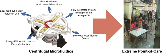
Challenges in the Use of Compact Disc-Based Centrifugal Microfluidics for Healthcare Diagnostics at the Extreme Point of Care


Abstract
: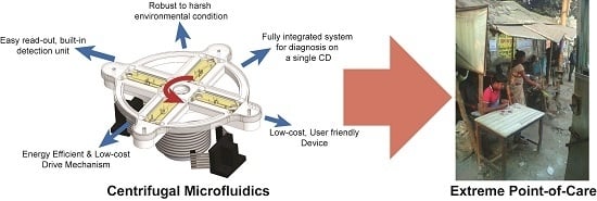
1. Introduction
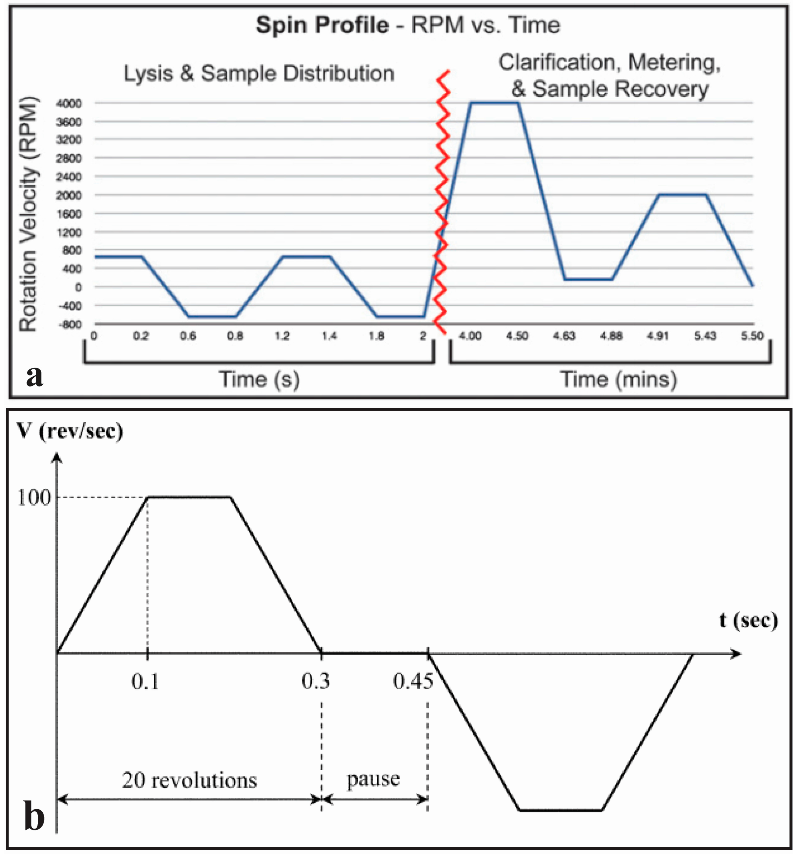
2. Fluid Actuation
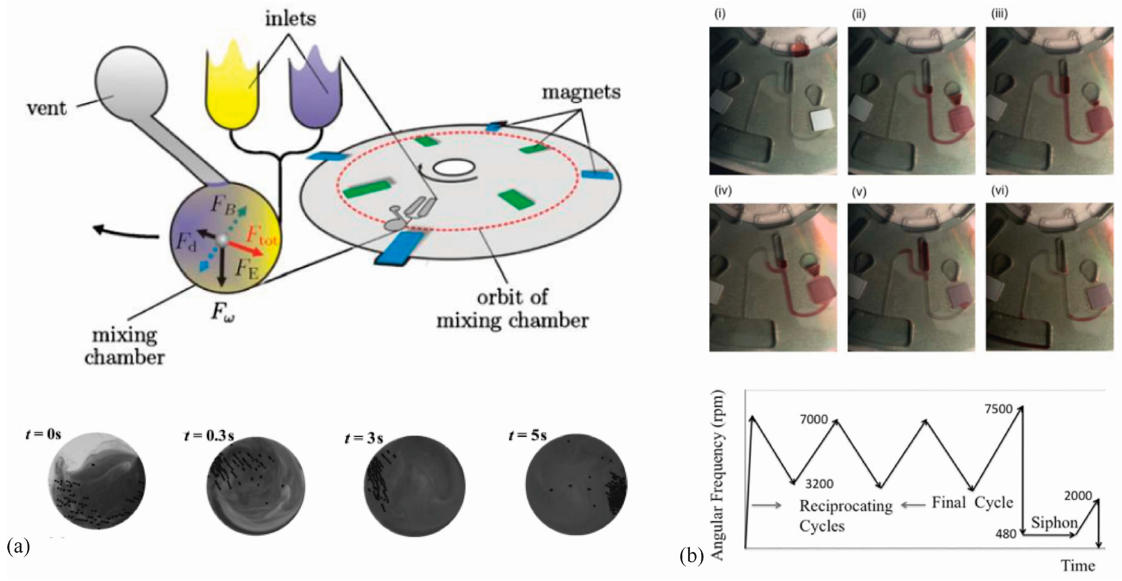
2.1. Fluid Mixing
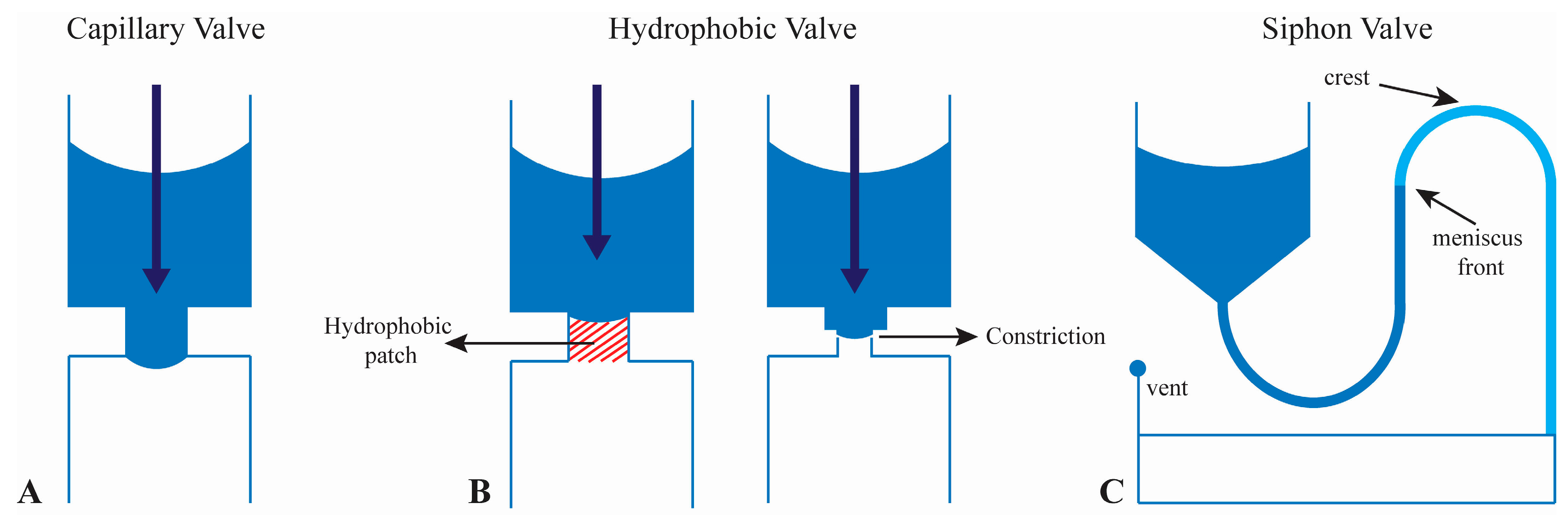
2.2. Valving
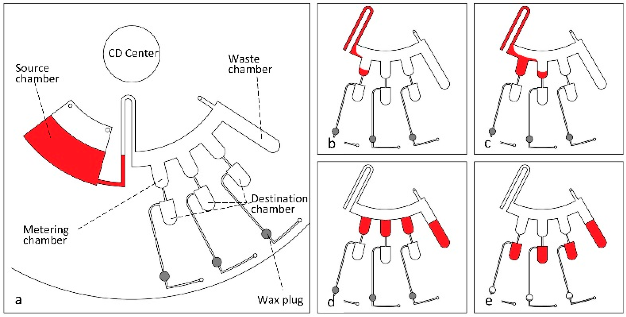
2.3. Volume Definition (Metering)
2.4. Multidirectional Actuation
2.5. Fluid Actuation: Challenges, and Recommendations for the Extreme POC
3. Drive Mechanisms
Drive Mechanisms: Challenges, and Recommendations for the Extreme POC
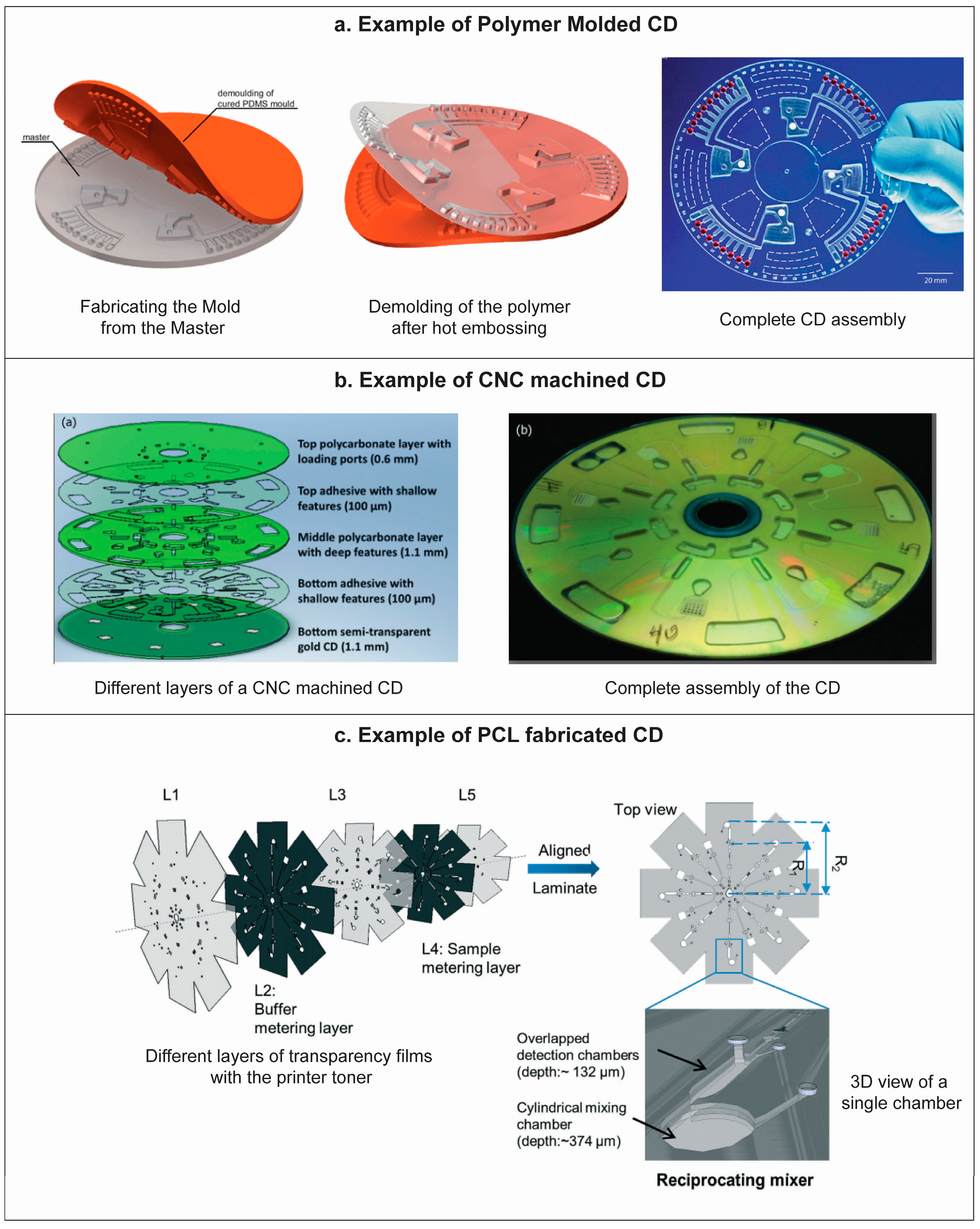
4. Manufacturing
Manufacturing: Challenges and Recommendations for the Extreme POC
5. Assays and Reagent Compatibility
5.1. Biological Fluids
5.2. Assay Reagents
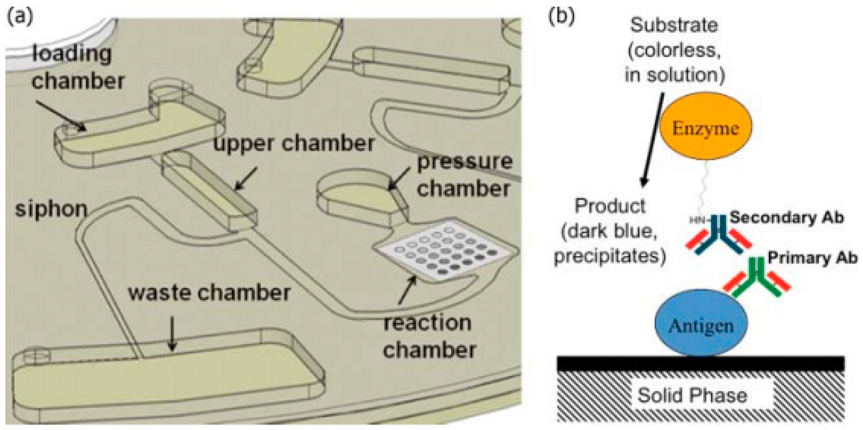
5.2.1. ELISA Reagents
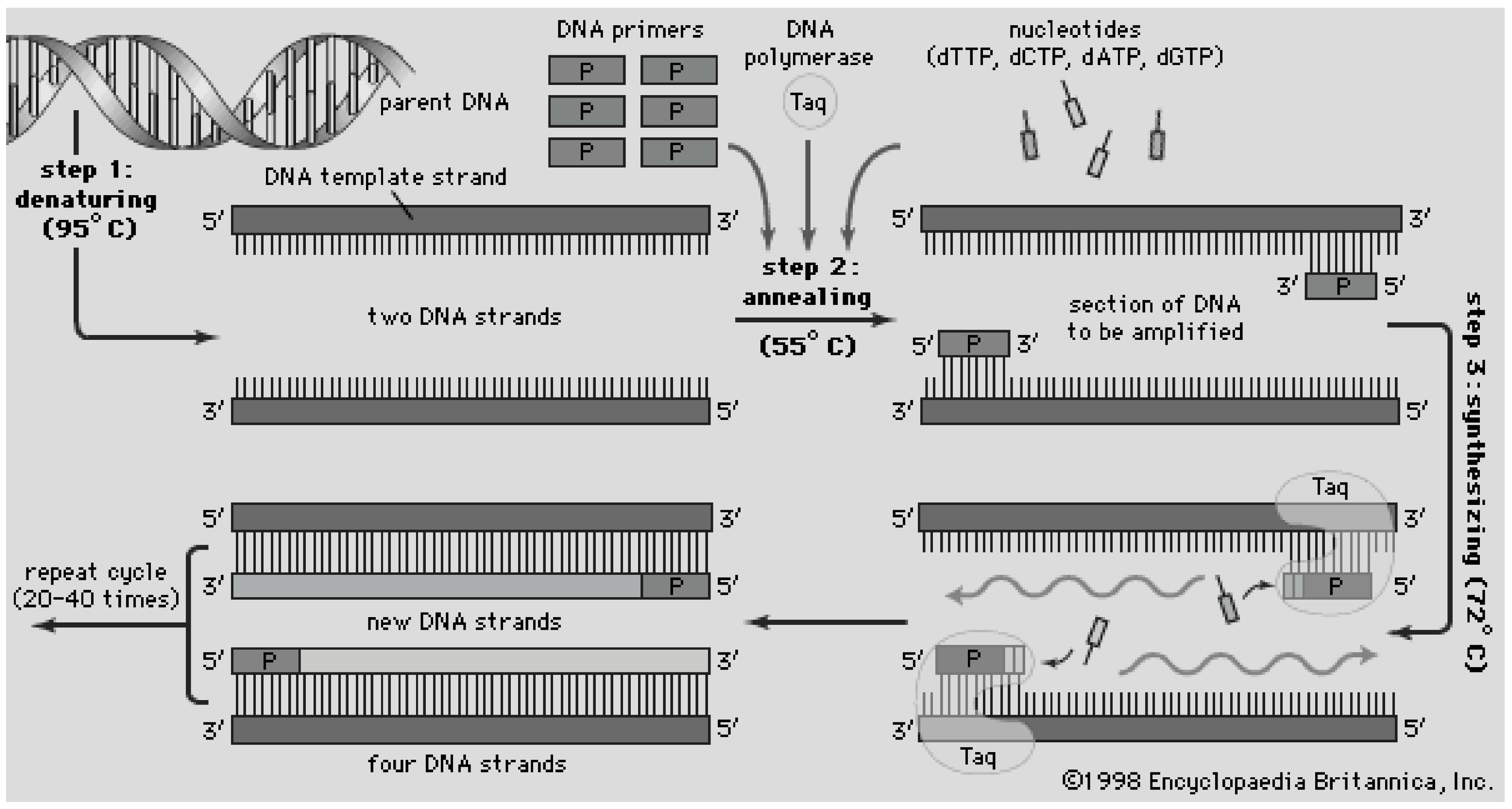
5.2.2. RT-PCR Reagents
5.2.3. Protein Assays
5.3. Assays and Reagent Compatibility: Challenges and Recommendation for the Extreme POC
6. Detection
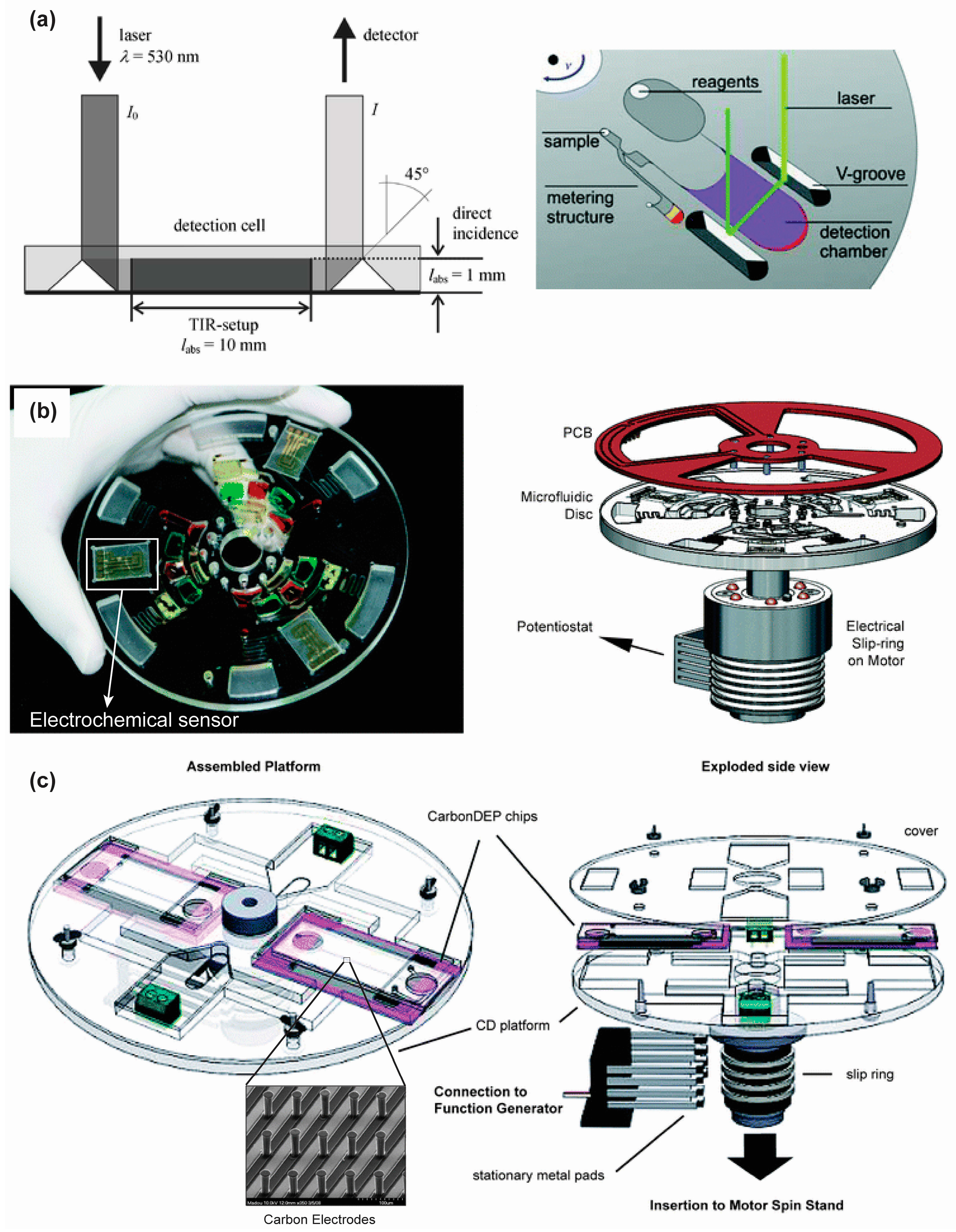
6.1. Optical Detection
6.1.1. Fluorescence Detection
6.1.2. Absorbance Detection
6.1.3. Chemiluminescence Detection
6.2. Electrochemical Detection
6.3. Detection: Challenges and Recommendations for the Extreme POC
7. Multiplexing or Multi-Directional Flow-Several Patients at Once, or One Full Assay on Disc per Patient
Multiplexing: Applications, Challenges and Recommendations for the Extreme POC
8. Disposal—An Important Consideration for the Extreme POC
9. Conclusions
- Development of fluid actuation schemes, i.e., mixing and valving, that do not require the manufacturing of complex microfluidic channel designs and complex spinning protocols;
- Development of technology to manufacture inexpensive, robust, and completely biodegradable discs for reliable transportation, storage, and easy and safe disposal of contaminated components;
- Development of temperature-independent and robust reagents, and storage schemes to avoid contamination and degradation of assay components over long periods of time;
- An assay result that is binary and can be unambiguously read by a broad audience regardless of their cultural or technical background;
- Minimize the need for sample preparation, complex equipment, expertise, and controlled environmental conditions to decrease the likelihood of experimental errors and contamination.
Acknowledgments
Author Contributions
Conflicts of Interest
References
- Peeling, R.W.; Mabey, D. Point-of-care tests for diagnosing infections in the developing world. Clin. Microbiol. Infect. 2010, 16, 1062–1069. [Google Scholar] [CrossRef] [PubMed]
- Dungchai, W.; Chailapakul, O.; Henry, C.S. Electrochemical detection for paper-based microfluidics. Anal. Chem. 2009, 81, 5821–5826. [Google Scholar] [CrossRef] [PubMed]
- Lankelma, J.; Nie, Z.; Carrilho, E.; Whitesides, G.M. Paper-based analytical device for electrochemical flow-injection analysis of glucose in urine. Anal. Chem. 2012, 84, 4147–4152. [Google Scholar] [CrossRef] [PubMed]
- Martinez, A.W.; Phillips, S.T.; Carrilho, E.; Thomas, S.W.; Sindi, H.; Whitesides, G.M. Simple telemedicine for developing regions: Camera phones and paper-based microfluidic devices for real-time, off-site diagnosis. Anal. Chem. 2008, 80, 3699–3707. [Google Scholar] [CrossRef] [PubMed]
- Heller, A.; Feldman, B. Electrochemical glucose sensors and their applications in diabetes management. Chem. Rev. 2008, 108, 2482–2505. [Google Scholar] [CrossRef] [PubMed]
- Vella, S.J.; Beattie, P.; Cademartiri, R.; Laromaine, A.; Martinez, A.W.; Phillips, S.T.; Mirica, K.A.; Whitesides, G.M. Measuring markers of liver function using a micropatterned paper device designed for blood from a fingerstick. Anal. Chem. 2012, 84, 2883–2891. [Google Scholar] [CrossRef] [PubMed]
- Cheng, C.-M.; Martinez, A.W.; Gong, J.; Mace, C.R.; Phillips, S.T.; Carrilho, E.; Mirica, K.A.; Whitesides, G.M. Paper-based ELISA. Angew. Chem. Int. Ed. Engl. 2010, 49, 4771–4774. [Google Scholar] [CrossRef] [PubMed]
- Liu, H.; Crooks, R.M. Three-dimensional paper microfluidic devices assembled using the principles of origami. J. Am. Chem. Soc. 2011, 133, 17564–17566. [Google Scholar] [CrossRef] [PubMed]
- Apilux, A.; Ukita, Y.; Chikae, M.; Chailapakul, O.; Takamura, Y. Development of automated paper-based devices for sequential multistep sandwich enzyme-linked immunosorbent assays using inkjet printing. Lab Chip 2013, 13, 126–135. [Google Scholar] [CrossRef] [PubMed]
- Hu, J.; Wang, S.; Wang, L.; Li, F.; Pingguan-Murphy, B.; Lu, T.J.; Xu, F. Advances in paper-based point-of-care diagnostics. Biosens. Bioelectron. 2014, 54, 585–597. [Google Scholar] [CrossRef] [PubMed]
- Martinez, A.W.; Phillips, S.T.; Whitesides, G.M.; Carrilho, E. Diagnostics for the developing world: Microfluidic paper-based analytical devices. Anal. Chem. 2010, 82, 3–10. [Google Scholar] [CrossRef] [PubMed]
- Li, X.; Ballerini, D.R.; Shen, W. A perspective on paper-based microfluidics: Current status and future trends. Biomicrofluidics 2012, 6, 011301. [Google Scholar] [CrossRef] [PubMed]
- Piccolo express. 2015. Available online: http://www.piccoloxpress.com/products/piccolo/overview/ (accessed on 15 December 2015).
- Gyrolab CDs. 2015. Available online: http://www.gyros.com/products/gyrolab-cds/#sthash.KKASrtMe.dpbs (accessed on 15 December 2015).
- Chin, C.; Linder, V.; Sia, S. Commercialization of microfluidic point-of-care diagnostic devices. Lab. Chip. 2012, 12, 2118–2134. [Google Scholar] [CrossRef] [PubMed]
- Gubala, V.; Harris, L.F.; Ricco, A.J.; Tan, M.X.; Williams, D.E. Point of care diagnostics: status and future. Anal. Chem. 2012, 84, 487–515. [Google Scholar] [CrossRef] [PubMed]
- Yetisen, A.K.; Akram, M.S.; Lowe, C.R. Paper-based microfluidic point-of-care diagnostic devices. Lab Chip 2013, 13, 2210–2251. [Google Scholar] [CrossRef] [PubMed]
- Chin, C.D.; Laksanasopin, T.; Cheung, Y.K.; Steinmiller, D.; Linder, V.; Parsa, H.; Wang, J.; Moore, H.; Rouse, R.; Umviligihozo, G. Microfluidics-based diagnostics of infectious diseases in the developing world. Nat. Med. 2011, 17, 1015–1019. [Google Scholar] [CrossRef] [PubMed]
- Madou, M.; Zoval, J.; Jia, G.; Kido, H.; Kim, J.; Kim, N. Lab on a CD. Annu. Rev. Biomed. Eng. 2006, 8, 601–628. [Google Scholar] [CrossRef] [PubMed]
- Ducrée, J.; Haeberle, S.; Lutz, S. The centrifugal microfluidic Bio-Disk platform. J. Micromech. Microeng. 2007, 17, S103. [Google Scholar] [CrossRef]
- Gorkin, R.; Park, J.; Siegrist, J.; Amasia, M.; Lee, B.S.; Park, J.-M.; Kim, J.; Kim, H.; Madou, M.; Cho, Y.-K. Centrifugal microfluidics for biomedical applications. Lab Chip 2010, 10, 1758–1773. [Google Scholar] [CrossRef] [PubMed]
- Smith, S.; Mager, D.; Perebikovsky, A.; Shamloo, E.; Kinahan, D.; Mishra, R.; Delgado, S.T.; Kido, H.; Saha, S.; Ducrée, J.; et al. CD-Based Microfluidics for Primary Care in Extreme Point-of-Care Settings. Micromachines 2016, 7, 22. [Google Scholar] [CrossRef]
- Burtis, C.A.; Johnson, W.F.; Mailen, J.C.; Overton, J.B.; Tiffany, T.O.; Watsky, M.B. Development of an Analytical System Based Around a Miniature Fast Analyzer. Clin. Chem. 1973, 19, 895–903. [Google Scholar] [PubMed]
- Grumann, M.; Geipel, A.; Riegger, L.; Zengerle, R.; Ducrée, J. Batch-mode mixing on centrifugal microfluidic platforms. Lab Chip 2005, 5, 560–565. [Google Scholar] [CrossRef] [PubMed]
- Kim, D.S.; Lee, I.H.; Kwon, T.H.; Cho, D.W. A novel chaotic micromixer: Barrier embedded Kenics micromixer. In Proceedings of the 7th International Conference on Miniaturized Chemical and Biochemical Analysts Systems , Squaw Valley, CA, USA, 5–9 October 2003; pp. 73–76.
- Ducrée, J.; Brenner, T.; Glatzel, T.; Zengerle, R. A Coriolis-based split-and-recombine laminator for ultrafast mixing on rotating disks. In Proceedings of the 7th International Conference on Micro Total Analysis Systems, Squaw Valley, CA, USA, 5–9 October 2003; pp. 603–606.
- Rida, A.; Lehnert, T.; Gijs, M. Microfluidic mixer using magnetic beads. In Proceedings of the 7th International Conference on Miniaturized Chemical and Biochemical Analysis Systems, Squaw Valley, CA, USA, 5–9 October 2003; pp. 579–582.
- Rong, R.; Choi, J.; Ahn, C. A novel magnetic chaotic mixer for in-flow mixing of magnetic beads. In Proceedings of the 7th International Conference on Micro Total Analysis Systems (µTAS 2003), Squaw Valley, CA, USA, 5–9 October 2003.
- Noroozi, Z.; Kido, H.; Peytavi, R. Centrifugal fluidic system for enhanced mixing and reducing incubation times during protein microarray processing. In Proceedings of the 14th International Conference on Miniaturised Systems for Chemistry and Life Sciences, Groningen, The Netherlands, 3–7 October 2010.
- Noroozi, Z.; Kido, H.; Peytavi, R.; Nakajima-Sasaki, R.; Jasinskas, A.; Micic, M.; Felgner, P.L.; Madou, M.J. A multiplexed immunoassay system based upon reciprocating centrifugal microfluidics. Rev. Sci. Instrum. 2011, 82, 064303. [Google Scholar] [CrossRef] [PubMed] [Green Version]
- Siegrist, J.; Gorkin, R.; Clime, L.; Roy, E.; Peytavi, R.; Kido, H.; Bergeron, M.; Veres, T.; Madou, M. Serial siphon valving for centrifugal microfluidic platforms. Microfluid. Nanofluid. 2010, 9, 55–63. [Google Scholar] [CrossRef]
- Cho, H.; Kim, H.; Kang, J.; Kim, T. How the capillary burst microvalve works. J. Colloid Interface Sci. 2007, 306, 379–385. [Google Scholar] [CrossRef] [PubMed]
- Chen, J.; Huang, P.; Lin, M. Analysis and experiment of capillary valves for microfluidics on a rotating disk. Microfluid. Nanofluid. 2008, 4, 427–437. [Google Scholar] [CrossRef]
- Siegrist, J.; Gorkin, R.; Bastien, M.; Stewart, G.; Peytavi, R.; Kido, H.; Bergeron, M.; Madou, M. Validation of a centrifugal microfluidic sample lysis and homogenization platform for nucleic acid extraction with clinical samples. Lab Chip 2010, 10, 363–371. [Google Scholar] [CrossRef] [PubMed]
- Beebe, D. Physics and applications of microfluidics in biology. Annu. Rev. Biomed. Eng. 2002, 4, 261–286. [Google Scholar] [CrossRef] [PubMed]
- Tiensuu, A.; Öhman, O. Hydrophobic valves by ink-jet printing on plastic CDs with integrated microfluidics. In Proceedings of the Micro Total Analysis Systems 2000 Symposium, Enschede, The Netherlands, 14–18 May 2000; pp. 575–578.
- Kido, H.; Micic, M.; Smith, D.; Zoval, J. A novel, compact disk-like centrifugal microfluidics system for cell lysis and sample homogenization. Colloids Surf B Biointerfaces 2007, 48, 44–51. [Google Scholar] [CrossRef] [PubMed]
- Beaulieu, I.; Geissler, M.; Mauzeroll, J. Oxygen plasma treatment of polystyrene and zeonor: Substrates for adhesion of patterned cells. Langmuir 2009, 25, 7169–7176. [Google Scholar] [CrossRef] [PubMed]
- Larsson, A.; Dérand, H. Stability of polycarbonate and polystyrene surfaces after hydrophilization with high intensity oxygen RF plasma. J. Colloid Interface Sci. 2002, 246, 214–221. [Google Scholar] [CrossRef] [PubMed]
- Abi-Samra, K.; Hanson, R.; Madou, R.G.M., III. Infrared controlled waxes for liquid handling and storage on a CD-microfluidic platform. Lab Chip 2011, 11, 723–726. [Google Scholar] [CrossRef] [PubMed]
- Haeberle, S.; Schmitt, N.; Zengerle, R.; Ducrée, J. Centrifugo-magnetic pump for gas-to-liquid sampling. Sens. Actuators A Phys. 2007, 135, 28–33. [Google Scholar] [CrossRef]
- Gorkin, R., III; Clime, L.; Madou, M.; Kido, H. Pneumatic pumping in centrifugal microfluidic platforms. Microfluid. Nanofluid. 2010, 9, 541–549. [Google Scholar] [CrossRef]
- Al-Faqheri, W.; Ibrahim, F.; Thio, T. Vacuum/compression valving (VCV) using parrafin-wax on a centrifugal microfluidic CD platform. PLoS ONE 2013, 8, e58523. [Google Scholar]
- Honda, N.; Lindberg, U.; Andersson, P.; Hoffmann, S.; Takei, H. Simultaneous multiple immunoassays in a compact disc-shaped microfluidic device based on centrifugal force. Clin. Chem. 2005, 51, 1955–1961. [Google Scholar] [CrossRef] [PubMed]
- Steigert, J.; Grumann, M.; Dube, M.; Streule, W.; Riegger, L.; Brenner, T.; Koltay, P.; Mittmann, K.; Zengerle, R.; Ducrée, J. Direct hemoglobin measurement on a centrifugal microfluidic platform for point-of-care diagnostics. Sens. Actuators A Phys. 2006, 130–131, 228–233. [Google Scholar] [CrossRef]
- Riegger, L.; Steigert, J.; Grumann, M. Disk-based parallel chemiluminescent detection of diagnostic markers for acute myocardial infarction. In Proceedings of the 10th International Conference on Miniaturized System for Chemisty and Life Sciences, Tokyo, Japan, 5–9 November 2006.
- Riegger, L.; Grumann, M.; Steigert, J.; Lutz, S.; Steinert, C.P.; Mueller, C.; Viertel, J.; Prucker, O.; Rühe, J.; Zengerle, R.; et al. Single-step centrifugal hematocrit determination on a 10-$ processing device. Biomed. Microdevices 2007, 9, 795–799. [Google Scholar] [CrossRef] [PubMed]
- Potyrailo, R.A.; Morris, W.G.; Leach, A.M.; Sivavec, T.M.; Wisnudel, M.B.; Boyette, S. Analog signal acquisition from computer optical disk drives for quantitative chemical sensing. Anal. Chem. 2006, 78, 5893–5899. [Google Scholar] [CrossRef] [PubMed]
- Date, A.; Pasini, P.; Daunert, S. Integration of spore-based genetically engineered whole-cell sensing systems into portable centrifugal microfluidic platforms. Anal. Bioanal. Chem. 2010, 398, 349–356. [Google Scholar] [CrossRef] [PubMed]
- Johnson, R.D.; Badr, I.H.A.; Barrett, G.; Lai, S.; Lu, Y.; Madou, M.J.; Bachas, L.G. Development of a Fully Integrated Analysis System for Ions Based on Ion-Selective Optodes and Centrifugal Microfluidics. Anal. Chem. 2001, 73, 3940–3946. [Google Scholar] [CrossRef] [PubMed]
- Ibrahim, F.; Jahanshahi, P.; Rahman, N.A.; Madou, M.; Nozari, A.A.; Soin, N.; Samra, K.A. Analysis and experiment of centrifugal force for microfluidic ELISA CD platform. In Proceedings of the 2010 IEEE EMBS Conference on Biomedical Engineering and Sciences (IECBES), Kuala Lumpur, Malaysia, 30 November–2 December 2010; pp. 466–470.
- Puckett, L.; Dikici, E.; Lai, S. Investigation into the applicability of the centrifugal microfluidics platform for the development of protein-ligand binding assays incorporating enhanced green fluorescent protein as a fluorescent reporter. Anal. Chem. 2004, 76, 7263–7268. [Google Scholar] [CrossRef] [PubMed]
- Brown, J.; Theis, L.; Kerr, L.; Zakhidova, N.; O’Connor, K.; Uthman, M.; Oden, Z.M.; Richards-Kortum, R. A hand-powered, portable, low-cost centrifuge for diagnosing anemia in low-resource settings. Am. J. Trop. Med. Hyg. 2011, 85, 327–332. [Google Scholar] [CrossRef] [PubMed]
- Wong, A.P.; Gupta, M.; Shevkoplyas, S.S.; Whitesides, G.M. Egg beater as centrifuge: Isolating human blood plasma from whole blood in resource-poor settings. Lab Chip 2008, 8, 2032–2037. [Google Scholar] [CrossRef] [PubMed]
- Kim, J.; Jang, S.H.; Jia, G.; Zoval, J.V.; da Silva, N.A.; Madou, M.J. Cell lysis on a microfluidic CD (compact disc). Lab Chip 2004, 4, 516–522. [Google Scholar] [CrossRef] [PubMed]
- Madou, M.J.; Lee, L.J.; W, K.K.; Sylvia, D.; Lai, S.; Koh, C.G.; Yi-Je, J.; Yu, L.; Lu, Y. Design and fabrication of polymer microfluidic platforms for biomedical applications. In Proceedings of the SPE 59th ANTEC, Dallas, TX, USA, 6–10 May 2001; pp. 2534–2538.
- Islam, M.; Natu, R.; Martinez-Duarte, R. A study on the limits and advantages of using a desktop cutter plotter to fabricate microfluidic networks. Microfluid. Nanofluid. 2015, 19, 973–985. [Google Scholar] [CrossRef]
- Thompson, B.L.; Ouyang, Y.; Duarte, G.R.M.; Carrilho, E.; Krauss, S.T.; Landers, J.P. Inexpensive, rapid prototyping of microfluidic devices using overhead transparencies and a laser print, cut and laminate fabrication method. Nat. Protoc. 2015, 10, 875–886. [Google Scholar] [CrossRef] [PubMed]
- Ouyang, Y.; Li, J.; Phaneuf, C.; Riehl, P.S.; Forest, C.; Begley, M.; Haverstick, D.M.; Landers, J.P. Multilevel fluidic flow control in a rotationally-driven polyester film microdevice created using laser print, cut and laminate. Lab Chip 2016, 16, 377–387. [Google Scholar] [CrossRef] [PubMed]
- Focke, M.; Stumpf, F.; Faltin, B.; Reith, P.; Bamarni, D.; Wadle, S.; Müller, C.; Reinecke, H.; Schrenzel, J.; Francois, P.; et al. Microstructuring of polymer films for sensitive genotyping by real-time PCR on a centrifugal microfluidic platform. Lab Chip 2010, 10, 2519–2526. [Google Scholar] [CrossRef] [PubMed]
- Haeberle, S.; Brenner, T.; Zengerle, R.; Ducrée, J. Centrifugal extraction of plasma from whole blood on a rotating disk. Lab Chip 2006, 6, 776–781. [Google Scholar] [CrossRef] [PubMed]
- Steigert, J.; Brenner, T.; Grumann, M.; Riegger, L.; Zengerle, R.; Ducree, J. Design and Fabrication of a Centrifugally Driven Microfluidic Disk for Fully Integrated Metabolic Assays on Whole Blood. In Proceedings of the 19th IEEE International Conference on Micro Electro Mechanical Systems, Istanbul, Turkey, 22–26 January 2006; pp. 418–421.[Green Version]
- Linares, A.; Gorkin, R., III; Glynn, B.; Godino, N.; Miller, N.; Kerin, M.; Ducrée, J. Purification of miRNA from whole blood by chemical lysis and phase separation in a centrifugo-pneumatic micro-homogenizer. In Proceedings of the 15th International Conference on Miniaturized Systems for Chemistry and Life Sciences, Seattle, WA, USA, 2–6 October 2011; pp. 1460–1462.
- Burger, R.; Kurzbuch, D.; Gorkin, R.; Kijanka, G.; Glynn, M.; McDonagh, C.; Ducrée, J. An integrated centrifugo-opto-microfluidic platform for arraying, analysis, identification and manipulation of individual cells. Lab Chip 2015, 15, 378–381. [Google Scholar] [CrossRef] [PubMed]
- Zhang, J.; Guo, Q.; Liu, M.; Yang, J. A lab-on-CD prototype for high-speed blood separation. J. Micromech. Microeng. 2008, 18, 125025. [Google Scholar] [CrossRef]
- Wang, L.; Li, P.C.H.; Yu, H.-Z.; Parameswaran, A.M. Fungal pathogenic nucleic acid detection achieved with a microfluidic microarray device. Anal. Chim. Acta 2008, 610, 97–104. [Google Scholar] [CrossRef] [PubMed]
- Czugala, M.; Maher, D.; Collins, F.; Burger, R.; Hopfgartner, F.; Yang, Y.; Zhaou, J.; Ducrée, J.; Smeaton, A.; Fraser, K.J.; et al. CMAS: Fully integrated portable centrifugal microfluidic analysis system for on-site colorimetric analysis. RSC Adv. 2013, 3, 15928. [Google Scholar] [CrossRef]
- Nwankire, C.E.; Czugala, M.; Burger, R.; Fraser, K.J.; O’Connell, T.M.; Glennon, T.; Onwuliri, B.E.; Nduaguibe, I.E.; Diamond, D.; Ducrée, J. A portable centrifugal analyser for liver function screening. Biosens. Bioelectron. 2014, 56, 352–358. [Google Scholar] [CrossRef] [PubMed]
- Dimov, N.; Gaughran, J.; Auley, D.M.; Boyle, D.; Kinahan, D.J.; Ducree, J. Centrifugally automated solid-phase purification of RNA. In Proceedings of the 2014 IEEE 27th International Conference on Micro Electro Mechanical Systems (MEMS), San Francisco, CA, USA, 26–30 Janunary 2014; pp. 260–263.
- Kinahan, D.J.; Kearney, S.M.; Glynn, M.T.; Ducrée, J. Spira mirabilis enhanced whole blood processing in a lab-on-a-disk. Sens. Actuators A Phys. 2014, 215, 71–76. [Google Scholar] [CrossRef]
- Nwankire, C.E.; Venkatanarayanan, A.; Glennon, T.; Keyes, T.E.; Forster, R.J.; Ducrée, J. Label-free impedance detection of cancer cells from whole blood on an integrated centrifugal microfluidic platform. Biosens. Bioelectron. 2015, 68, 382–389. [Google Scholar] [CrossRef] [PubMed]
- Lee, B.S.; Lee, J.-N.; Park, J.-M.; Lee, J.-G.; Kim, S.; Cho, Y.-K.; Ko, C. A fully automated immunoassay from whole blood on a disc. Lab Chip 2009, 9, 1548–1555. [Google Scholar] [CrossRef] [PubMed]
- Park, J.; Kim, M.; Moon, H.; Yoo, C. Fully automated circulating tumor cell isolation platform with large-volume capacity based on lab-on-a-disc. Anal. Chem. 2014, 86, 3735–3742. [Google Scholar] [CrossRef] [PubMed]
- Duffy, D.; Gillis, H.; Lin, J. Microfabricated centrifugal microfluidic systems: Characterization and multiple enzymatic assays. Anal. Chem. 1999, 71, 4669–4678. [Google Scholar] [CrossRef]
- Schaff, U.; Sommer, G. Whole blood immunoassay based on centrifugal bead sedimentation. Clin. Chem. 2011, 57, 753–761. [Google Scholar] [CrossRef] [PubMed]
- Lequin, R.M. Enzyme immunoassay (EIA)/enzyme-linked immunosorbent assay (ELISA). Clin. Chem. 2005, 51, 2415–2418. [Google Scholar] [CrossRef] [PubMed]
- Lai, S.; Wang, S.; Luo, J.; Lee, L.J.; Yang, S.-T.; Madou, M. J. Design of a compact disk-like microfluidic platform for enzyme-linked immunosorbent assay. Anal. Chem. 2004, 76, 1832–1837. [Google Scholar] [CrossRef] [PubMed]
- Cho, Y.; Lee, J.; Park, J.; Lee, B.; Lee, Y.; Ko, C. One-step pathogen specific DNA extraction from whole blood on a centrifugal microfluidic device. Lab Chip 2007, 7, 565–573. [Google Scholar] [CrossRef] [PubMed]
- Lutz, S.; Weber, P.; Focke, M.; Faltin, B. Microfluidic lab-on-a-foil for nucleic acid analysis based on isothermal recombinase polymerase amplification (RPA). Lab Chip 2010, 10, 887–893. [Google Scholar] [CrossRef] [PubMed]
- Amasia, M.; Cozzens, M.; Madou, M.J. Centrifugal microfluidic platform for rapid PCR amplification using integrated thermoelectric heating and ice-valving. Sens. Actuators B Chem. 2012, 161, 1191–1197. [Google Scholar] [CrossRef]
- PCR Lab. Available online: https://faculty.unlv.edu/wmojica/PCR_LAB2.htm (accessed on 15 December 2015).
- La, M.; Park, S.M.; Kim, D.S. Centrifugal multiplexing fixed-volume dispenser on a plastic lab-on-a-disk for parallel biochemical single-end-point assays. Biomicrofluidics 2015, 9, 014104. [Google Scholar] [CrossRef] [PubMed]
- Rothert, A.; Deo, S.; Millner, L.; Puckett, L. Whole-cell-reporter-gene-based biosensing systems on a compact disk microfluidics platform. Anal. Biochem. 2005, 342, 11–19. [Google Scholar] [CrossRef] [PubMed]
- Le Nel, A.; Minc, N.; Smadja, C.; Slovakova, M.; Bilkova, Z.; Peyrin, J.-M.; Viovy, J.-L.; Taverna, M. Controlled proteolysis of normal and pathological prion protein in a microfluidic chip. Lab Chip 2008, 8, 294–301. [Google Scholar] [CrossRef] [PubMed]
- Tan, H.Y.; Loke, W.K.; Tan, Y.T.; Nguyen, N.-T. A lab-on-a-chip for detection of nerve agent sarin in blood. Lab Chip 2008, 8, 885–891. [Google Scholar] [CrossRef] [PubMed]
- Liu, G.; Mao, X.; Phillips, J.A.; Xu, H.; Tan, W.; Zeng, L. Aptamer-nanoparticle strip biosensor for sensitive detection of cancer cells. Anal. Chem. 2009, 81, 10013–10018. [Google Scholar] [CrossRef] [PubMed]
- Liu, H.; Xiang, Y.; Lu, Y.; Crooks, R.M. Aptamer-Based Origami Paper Analytical Device for Electrochemical Detection of Adenosine. Angew. Chem. 2012, 124, 7031–7034. [Google Scholar] [CrossRef]
- Kell, A.J.; Stewart, G.; Ryan, S.; Peytavi, R.; Boissinot, M.; Huletsky, A.; Bergeron, M.G.; Simard, B. Vancomycin-modified nanoparticles for efficient targeting and preconcentration of Gram-positive and Gram-negative bacteria. ACS Nano 2008, 2, 1777–1788. [Google Scholar] [CrossRef] [PubMed]
- Foudeh, A.M.; Didar, T.F.; Veres, T.; Tabrizian, M. Microfluidic designs and techniques using lab-on-a-chip devices for pathogen detection for point-of-care diagnostics. Lab Chip 2012, 12, 3249–3266. [Google Scholar] [CrossRef] [PubMed]
- Riegger, L.; Grumann, M.; Nann, T. Read-out concepts for multiplexed bead-based fluorescence immunoassays on centrifugal microfluidic platforms. Sens. Actuators A Phys. 2006, 126, 455–462. [Google Scholar] [CrossRef]
- Jiang, H.; Weng, X.; Li, D. Microfluidic whole-blood immunoassays. Microfluid. Nanofluid. 2010, 10, 941–964. [Google Scholar] [CrossRef]
- Steigert, J.; Grumann, M.; Brenner, T.; Riegger, L.; Harter, J.; Zengerle, R.; Ducrée, J. Fully integrated whole blood testing by real-time absorption measurement on a centrifugal platform. Lab Chip 2006, 6, 1040–1044. [Google Scholar] [CrossRef] [PubMed]
- Kim, T.-H.; Abi-Samra, K.; Sunkara, V.; Park, D.-K.; Amasia, M.; Kim, N.; Kim, J.; Kim, H.; Madou, M.; Cho, Y.-K. Flow-enhanced electrochemical immunosensors on centrifugal microfluidic platforms. Lab Chip 2013, 13, 3747–3754. [Google Scholar] [CrossRef] [PubMed]
- Martinez-Duarte, R.; Gorkin, R.A.; Abi-Samra, K.; Madou, M.J. The integration of 3D carbon-electrode dielectrophoresis on a CD-like centrifugal microfluidic platform. Lab Chip 2010, 10, 1030–1043. [Google Scholar] [CrossRef] [PubMed]
- Andreasen, S.Z.; Kwasny, D.; Amato, L.; Brøgger, A.L.; Bosco, F.G.; Andersen, K.B.; Svendsen, W.E.; Boisen, A. Integrating electrochemical detection with centrifugal microfluidics for real-time and fully automated sample testing. RSC Adv. 2015, 5, 17187–17193. [Google Scholar] [CrossRef] [Green Version]
- Li, T.; Fan, Y.; Cheng, Y.; Yang, J. An electrochemical Lab-on-a-CD system for parallel whole blood analysis. Lab Chip 2013, 13, 2634–2640. [Google Scholar] [CrossRef] [PubMed]
- Madou, M.J. Solid-State Physics, Fluidics, and Analytical Techniques in Micro- and Nanotechnology; CRC Press: Boca Raton, FL, USA, 2011. [Google Scholar]
- Yang, L.; Bashir, R. Electrical/electrochemical impedance for rapid detection of foodborne pathogenic bacteria. Biotechnol. Adv. 2008, 26, 135–150. [Google Scholar] [CrossRef] [PubMed]
- Lehmann, R.G.; Miller, J.R.; Kozerski, G.E. Degradation of silicone polymer in a field soil under natural conditions. Chemosphere 2000, 41, 743–749. [Google Scholar] [CrossRef]
- Radhakrishnan, T.S. Thermal degradation of poly(dimethylsilylene) and poly(tetramethyldisilylene-co-styrene). J. Appl. Polym. Sci. 2006, 99, 2679–2686. [Google Scholar] [CrossRef]


| Drive Description | Power | Control | Relative Cost | Special Capability | References |
|---|---|---|---|---|---|
| Significantly Complex | |||||
| Gyrolab Workstation™ (Gyros AB, Uppsala, Sweden) | 120 VAC | Proprietary Software (Gyroloab Control (embedded), Gyrolab Evaluator (PC-based analysis)) | $$$$ | Laser-induced fluorescence detection, proprietary CDs, automated centrifugation control | [44] |
| Custom Colorimetric Hemoglobin Analyzer | 120 VAC | Standard motor drive software, with custom coding for actuation and sample loading | $$$ | Sample loading via Pipejet ™ (BioFluidix, Freiburg, Germany), laser and spectrophotometer, PC controlled actuation | [45] |
| Centrifuge with Photomultiplier Tube (PMT) | 120 VAC | Embedded motor control software, PMT read-out software | $$$ | PMT, x-y drive for PMT positioning | [46] |
| Moderately Complex | |||||
| CD-Read Only Memory (ROM) Drive | 120 VAC | ASPI driver for PC | $$ | Built-in laser driven optical system, limit of 6000 rpm | [20,47,48] |
| Stepper Motor + Driver | 12 VDC for drive actuation 120 VAC likely required for driver and user interface (computer) | Programming language with development environment (i.e., Visual BASIC, C, C++, LabVIEW) | $$ | Speed and torque only limited by rating of selected motor | [49,50] |
| Servo Motor + Driver | Programming language with development environment (i.e., Visual BASIC, C, C++, LabVIEW) | $$ | Speed and torque only limited by rating of selected motor | [42,51,52] | |
| Simple | |||||
| Hand-powered Centrifuge for Anemia Diagnosis | Manual | Manual (training may be required for consistency) | $ | Salad-spinner based design, approx. 600 rpm potential speed, tubes used (not CDs) | [53] |
| Egg-beater as Centrifuge for Blood Fractionization | Manual | Manual | $ | Approx. 1200 rpm potential speed, tubing used (not CDs) | [54] |
| Fabrication Technique | Material | Inexpensive | Disposable | Functionalities |
|---|---|---|---|---|
| Polymer Molding | COC | No | Yes | Extraction of plasma from whole blood [61], fully integrated metabolic assays on whole blood [62], direct measurement of hemoglobin from whole blood [45], hematocrit determination [47] |
| PDMS | No | No | Purification of CD4+ cells from blood sample [63], identification and manipulation of single cell [64], blood separation [65], cell lysis [55], micro-assays [66] | |
| CNC Machining | PMMA | Yes | Yes | Purification and separation of miRNA from whole blood [63], colorimetric analysis [67], liver function screening [68], purification of RNA [69], whole blood processing [70], label free cancer cell detection [71], immunoassay from whole blood [72] |
| Polycarbonate | Yes | Yes | Cell lysis and nucleic acid extraction [34] | |
| PCL Method | Polyester | Yes | Yes | Protein quantitation in blood [59] |
© 2016 by the authors. Licensee MDPI, Basel, Switzerland. This article is an open access article distributed under the terms and conditions of the Creative Commons by Attribution (CC-BY) license ( http://creativecommons.org/licenses/by/4.0/).
Share and Cite
Gilmore, J.; Islam, M.; Martinez-Duarte, R. Challenges in the Use of Compact Disc-Based Centrifugal Microfluidics for Healthcare Diagnostics at the Extreme Point of Care. Micromachines 2016, 7, 52. https://doi.org/10.3390/mi7040052
Gilmore J, Islam M, Martinez-Duarte R. Challenges in the Use of Compact Disc-Based Centrifugal Microfluidics for Healthcare Diagnostics at the Extreme Point of Care. Micromachines. 2016; 7(4):52. https://doi.org/10.3390/mi7040052
Chicago/Turabian StyleGilmore, Jordon, Monsur Islam, and Rodrigo Martinez-Duarte. 2016. "Challenges in the Use of Compact Disc-Based Centrifugal Microfluidics for Healthcare Diagnostics at the Extreme Point of Care" Micromachines 7, no. 4: 52. https://doi.org/10.3390/mi7040052