1. Introduction
Recently, there has been a trend toward developing compact and portable devices with user friendly interface for numerous biomedical and chemical applications [
1,
2,
3,
4]. Microfluidics is one of the promising platforms for developing portable devices that allow real-time screening and on-chip diagnosis [
5,
6]. In particular, the reconfigurable architecture of digital microfluidic (DMF) systems permits the real-time change of fluidic protocols on the same chip, which cannot be achieved in conventional continuous flow systems [
7,
8,
9,
10,
11,
12]. Although several attempts have been made to introduce continuous microfluidic operations inside portable devices [
13,
14], few studies have focused on developing portable DMF platforms [
15,
16,
17].
Modern electronic devices and fabrication technologies have enabled size reduction and miniaturization of the digital microfluidic systems without limiting their capabilities and functionalities. Gong
et al. [
16] have introduced a packaged DMF system with time multiplexed driving scheme in order to minimize the number of the control channels. Another research group has introduced a more advanced packaging for the DMF system in a portable box that can be controlled by a handheld tablet [
17,
18]. However, these attempts suffered from the complexity of the design and the high cost of the components used. Moreover, reproducing these devices is challenging and extensively time consuming.
One of the main challenges in developing portable and cost effective DMF systems is regarding the portability of the control modules, high voltage electrical components, and imaging and post processing systems. On the other hand, to avoid cross contamination, and also to be used for different applications, the DMF chips must be easily replaced. Recent advances in the hardware and software capabilities of smartphones creates an opportunity for development of these portable DMF systems [
1]. To address the above mentioned issues, three-dimensional (3D) printing can be used to integrate the smartphones with replaceable and modular DMF systems. Although smartphones and 3D printing technology have been used for numerous continuous microfluidic applications [
19,
20], their use have not been explored for DMF applications.
In this work, an ultra-portable low cost smartphone controlled DMF system in a 3D printed modular assembly is introduced. The main components of this system include holder assembly, battery-powered high voltage electronic circuitry and a smartphone controlling the digital microfluidic operations via Bluetooth connection. Overall, the developed assembly offers portability and modularity at lower cost with reduced complexity and easier fabrication. Another important advantage of this device is the compatibility with any smartphone that has a built-in camera and can communicate through a Bluetooth connection. Moreover, the assembled device does not require external peripherals such as high voltage amplifiers, external power source, microscopic camera, image analysis and post processing stations. The modular system reported here enhances the previous designs [
15,
16,
17,
21] as it is monitored and controlled by smartphones, and it is more compact, cost effective and can be easily reproduced.
2. Experimental Setup
A schematic hierarchy of the proposed ultra-compact DMF platform is shown in
Figure 1. Low cost high voltage battery powered amplifier circuit is designed to generate the voltage required for closed and open DMF systems. A microcontroller is used to control the DMF droplet motion and routing configuration. A smartphone is then used to communicate and send commands to the microcontroller. For this purpose, a Bluetooth module is used to send and receive commands and establish the connection with the microcontroller. The smartphone is also used to monitor the droplet motion and acts as a post processing station as it can perform image processing and detect any color changes. In order to increase the magnification, a microscopic lens is attached to the smartphone camera. The microscopic lens also helps in the size reduction of the device by decreasing the focal distance from the chip to the smartphone to 1 cm only. In addition, 3D printing is used to fabricate a modular holder assembly that allows the detachment of the DMF chip from the holder.
Figure 1.
A schematic hierarchy of the proposed ultra-compact digital microfluidic (DMF) platform where the smart phone is used to control the DMF operations: (a) The designed DMF chip with the electrode connections; (b) Low cost battery powered high voltage designed circuitry; (c) Microcontroller used in this work; (d) Microscopic lens; (e) Bluetooth module.
2.1. Chip Fabrication
Microfluidic chips can be categorized according to the type of the flow inside them such as continuous flow in closed microfluidic channels and discrete droplets motion on digital microfluidics systems. Several microfluidic operations can be performed in the continuous microfluidic systems such as droplet splitting [
22], droplet merging [
23], droplet dispensing [
24,
25]. Transport, merging, splitting and dispensing of discrete droplets have been demonstrated successfully on the DMF platform [
26,
27,
28].
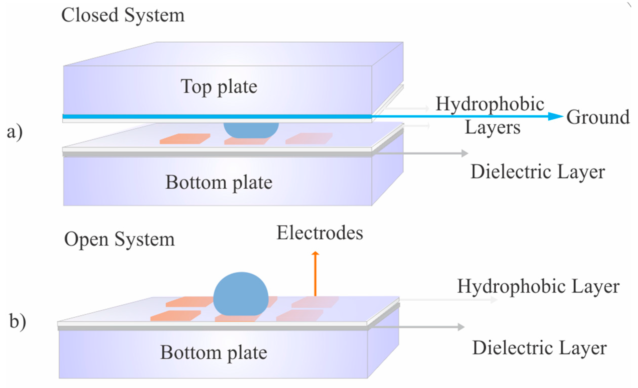
Digital microfluidic systems can manipulate discrete droplets using two main configurations: open and closed systems (see
Figure 2). Electrowetting on a dielectric (EWOD) is one the actuation techniques used to manipulate the droplets in both open and closed DMF devices [
29]. DMF chips can be fabricated by several methods such as photolithography [
30], inkjet printing, and rapid prototyping on paper substrates [
31,
32,
33]. Open and closed DMF systems may each offer some advantages and disadvantages for different applications. Using the open system enables dispensing the droplets easily by having direct access to the surface of the chip. Higher droplet velocities can be achieved by reducing the friction when the top plate is removed. However, open systems require higher voltages during droplet actuation. On the other hand, the evaporation in closed systems can be more controlled particularly when oil is used as a filler medium. Finally, closed systems have lower voltage requirements. On the contrary, closed systems have increased friction and lower droplet velocities with low mixing rates for the droplets.
In this work, EWOD-operated digital microfluidic chip is fabricated by conventional photolithographic technique. A Copper layer of 80 nm is deposited on a glass substrate by a sputtering deposition system (NEXDEP depositing system, Angstrom engineering, Kitchener, ON, Canada) followed by photoresist spin coating (S1813) at 2000 RPM for 26 s. to create a layer with thickness of 1.5 µm. Then, the photoresist layer is covered by a mask and exposed to ultraviolet (UV) light according to the designed patterns. The photoresist is developed in MF-319, and then the copper is etched in ferric chloride solution. Finally, Parylene-C of 10 µm thickness is deposited using a chemical vapour depositioning system (PDS 2010 Labcoter® Parylene Deposition System, Specialty Coating Systems, Indianapolis, IN, USA). The electrode size used in the experiments is 2 mm × 2 mm.
Figure 2.
The DMF system in closed and open configurations.
Figure 2.
The DMF system in closed and open configurations.
2.2. Holder Assembly
Three dimensional (3D) printing is an additive manufacturing process that can provide a precise, compact and rapidly prototyped packaging for the portable DMF systems. 3D printing has been used in different biomedical and engineering applications [
34,
35,
36]. For instance, microfluidic lab on a chip devices are 3D printed for chemical synthesis [
37] and for fabricating customizable chemical labware [
38]. Biomedical and tissue engineering has also benefited from the 3D printing technique [
39,
40,
41,
42]. Moreover, 3D printing technique has been used recently for fabricating micro lithium ion batteries [
43].
A 3D printer (Objet500 Connex, Stratasys, Eden Prairie, MN, USA) with a resolution of 14 µm is used to fabricate the DMF modular parts required for assembling the portable DMF device. The 3D printed holder assembly has the necessary components including chip frame and spacer, electrical connection holders, batteries, and phone holders.
2.3. Electrical Components
High voltages are usually required for actuating the electrodes in closed (typically 20 to 300 V) and open (typically 100 to 700 V) DMF systems. These voltage signals are usually generated by high cost and high power bench top equipment. However, the droplet actuation process requires low power and low current consumption (within the micro-watt range) [
44]. On the other hand, the high voltage amplifier circuit used in the literature [
16] utilized high cost commercial version of DC to DC converters that can reach 6000 V and the voltages required for DMF operations are typically lower than this value.
The main components of the electronic parts include a low cost and low power high voltage amplifier, a small and compact microcontroller, phone-to-microcontroller connections via Bluetooth, a high voltage switching circuit, a portable power supply (Lithium ion battery), and DMF chip-to-board connections.
A low power microcontroller (Arduino Micro, Ivrea, Italy) is chosen to control the high voltage switching circuit and route the droplets accordingly. A software program is developed for programming the microcontroller to route the droplets based on the required DMF operations. Moreover, this program is used for the communication between the smartphone and the microcontroller using the Bluetooth module to send and receive commands in serial communication mode.
Switched mode power supplies (SMPS) are used for converting electrical power from one form to another. SMPS are usually used to change voltage type and level in many electrical equipment including cell phone chargers. SMPS can be categorized according to the change that occurs in response to the output voltage type compared to the input voltage type. In this work, a boost DC to DC converter is used to yield the high voltages required for DMF operations from a DC battery source. Boost DC to DC converters are characterized by several advantages such as their compact size as small inductors can be used, they can operate at high efficiencies and the power consumption can be reduced to preserve the charge of the battery. Accordingly, boost DC to DC converters are used in this work to replace the highly powered, costly, and bulky bench-top equipment.
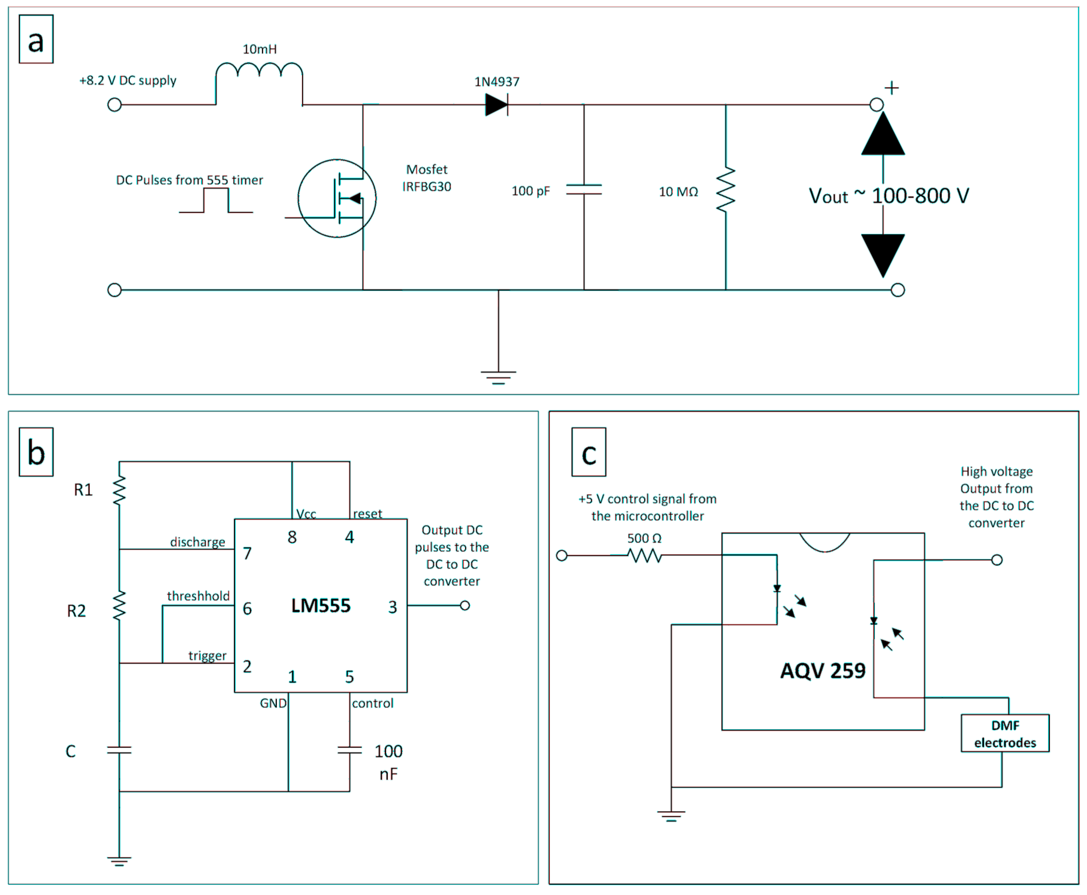
The circuit in
Figure 3 is designed to amplify the battery voltage generated from the two small lithium ion batteries from 8 V approximate up to 800 V. The output voltage can be controlled by either changing the pulse switching frequency or the duty cycle. More details about the circuit details can be found in the
supplementary data.
We developed a code to send and receive serial commands from the microcontroller to the smartphone and vice versa. The code is developed using Arduino 1.0.6 platform. The application used to send and receive commands from the smartphone is S2 Terminal for Bluetooth.
2.4. Imaging Accessories
A microscopic lens (Micro Phone Lens, Olympia, Washington, DC, USA) is integrated to the platform to analyze the droplet motion and monitor the DMF operations. The phone camera is used for detection as it can identify any change that occurs in the droplet color. The microscopic lens is attached easily on any smartphone camera by just pressing it gently on the surface of the camera. The magnification of the lens is 15× with working distance of 1 cm. An open source app (Color Analyzer), available on the smartphone app store, is used for detecting the color. For more advanced image analysis, the Open CV libraries can be used [
45].
Figure 3.
(a) Circuit diagram of the boost DC to DC converter used to generate high voltages from the battery source; (b) 555 timer circuit used to generate the pulses required for the switched mode power supply; (c) The high voltage switching circuit used to control the droplet routing.
Figure 3.
(a) Circuit diagram of the boost DC to DC converter used to generate high voltages from the battery source; (b) 555 timer circuit used to generate the pulses required for the switched mode power supply; (c) The high voltage switching circuit used to control the droplet routing.
3. Results and Discussion
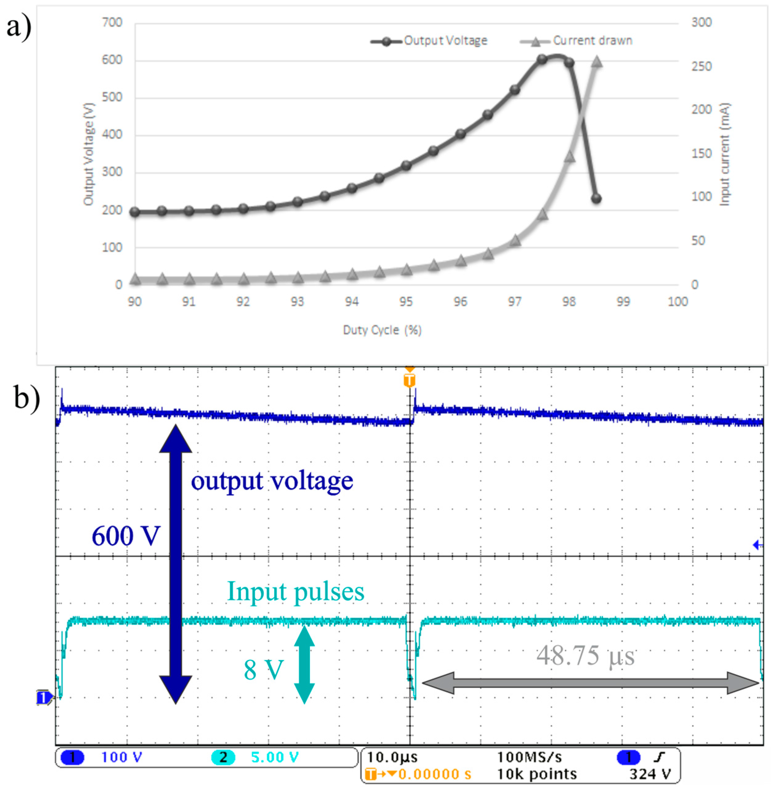
To demonstrate the effect of duty cycle on the output voltage, experiments were performed to change the duty cycle for the pulse frequency of 20 kHz. The current drawn by the circuit is also measured to determine the power consumption of the circuit. The duty cycle of the pulsating signal is the ratio between the time when the Metal-Oxide-Semiconductor Field-Effect Transistor (MOSFET) is on and the total periodic time of the signal. The duty cycle of the signal controls the voltage gain ratio between the output and the input voltages. As the duty cycle increases, the voltage gain increases as shown in
Figure 4a and Equation (1) in the
supplementary materials. In addition, the current drawn by the circuit also increases by increasing the duty cycle. The current drawn increases significantly beyond 100 mA when the duty cycle passes beyond 97.5%. It should be noted that current consumption must be reduced to preserve the battery power.
Figure 4b shows the output voltage wave form and the input switching pulses going from the 555 timer to the MOSFET when the duty cycle is 97.5% and the frequency is 20 kHz. The experiment in
Figure 4b depicts that the 600 V output voltage wave form generated has a voltage ripple of ±20 V which is around 3% of the total output voltage.
The output voltage can also be controlled by changing the switching frequency.
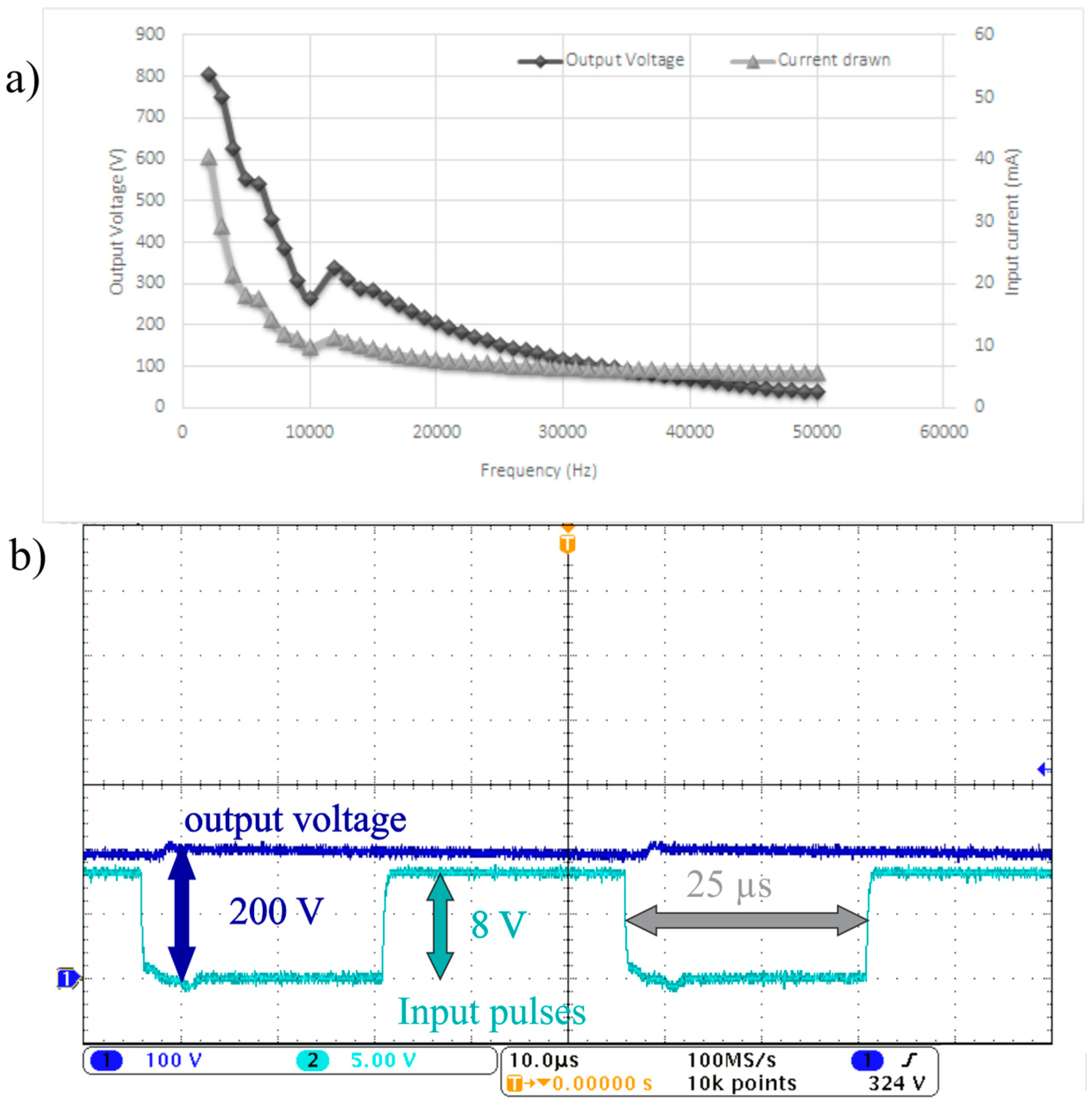
Figure 5a shows the average output voltage generated across different frequencies when the duty cycle is kept constant at 50%. As shown in
Figure 5a, the current drawn from the batteries is less than 50 mA across any tested frequencies which indicates low power consumption at these operation modes.
Figure 5b depicts the output voltage and the switching pulses going from the 555 timer to the MOSFET when the duty cycle is 50% and the frequency is 20 kHz. The average output voltage is 200 V and the ripple in this case is ±5 V which is around 2.5% of the total output voltage. It is worthy to note that using low frequencies is not preferable as the output voltage exhibits high voltage ripple at lower frequencies below the 10 kHz range. On the whole, the designed circuits are able to generate the high voltages required and take advantage of the low power consumption of the DMF system. A high voltage regulator circuit can be added to rectify the output signal generated. However, the current output wave form is adequate for DMF operations as it is shown later in this work.
Figure 4.
(a) The output voltage generated experimentally from the DC to DC boost converter and the current drawn versus the duty cycle when the frequency is 20 kHz. (b) The output voltage waveform (Dark Blue) and the switching pulses waveform (Cyan) when the duty cycle is 97.5% and the frequency is 20 kHz where the vertical scale is for the output voltage waveform and the switching pulses waveform is 100 and 5 V, respectively.
Figure 5.
(a) The output voltage generated experimentally from the DC to DC boost converter and the current drawn versus the frequency when the duty cycle is 50%; (b) The output voltage waveform (Dark Blue) and the switching pulses waveform (Cyan) when the duty cycle is 50% and the frequency is 20 kHz where the vertical scale where the vertical scale for the output voltage waveform and the switching pulse waveform is 100 and 5 V, respectively.
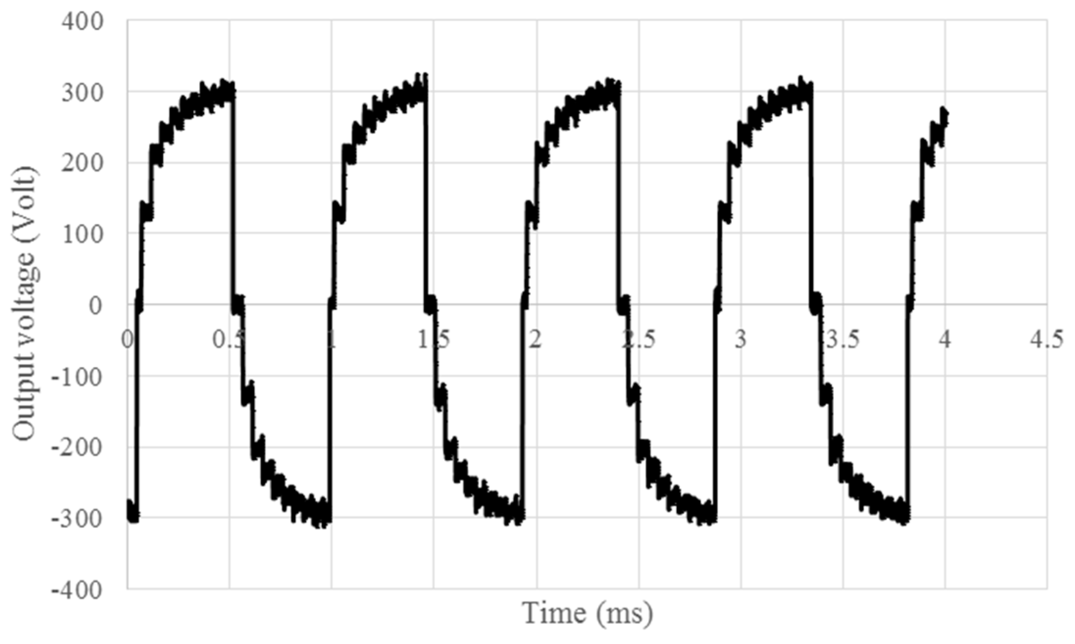
Afterwards, the high voltage output of the boost DC to DC converter is chopped with the full bridge circuit to an AC square wave signal, demonstrated in
Figure 6, and then forwarded to the switching circuit in
Figure 3c. The sequential voltage control algorithm is programmed on the microcontroller which sends a 5 V signal to the switching circuit which in turn activate the desired electrode. The Bluetooth module integrated to the system is used to send and receive commands from the phone and communicate with the microcontroller. All these circuits are packaged in the device shown in
Figure 7 and
Figure 8. The total power consumption of the device with all the peripheral circuits has to be determined in order to assess the attainable operation time when batteries are used as a power source. The total current drawn by the system including the DC to DC converter, the 555 oscillator circuit, the high voltage switching circuit, the microcontroller, and the Bluetooth module is 180 mA when these circuits are running simultaneously. Therefore, the total power consumption full power operation mode is around 1.47 watts. This amount of current can run the system in continuous operation mode for more than 22 h on the two small lithium ion batteries with total capacity of 4000 mAh. This total current consumption of the system is measured when the system runs at full power. However, the sequence of the DMF operations and post processing do not require running all of them simultaneously. Therefore, additional running time can be achieved by switching off some circuits and putting them to sleep mode based on the DMF schedule of operation.
Figure 6.
The 600 Vpp (Peak to peak voltage) output AC signal from the circuits used in moving the droplets.
Figure 6.
The 600 Vpp (Peak to peak voltage) output AC signal from the circuits used in moving the droplets.
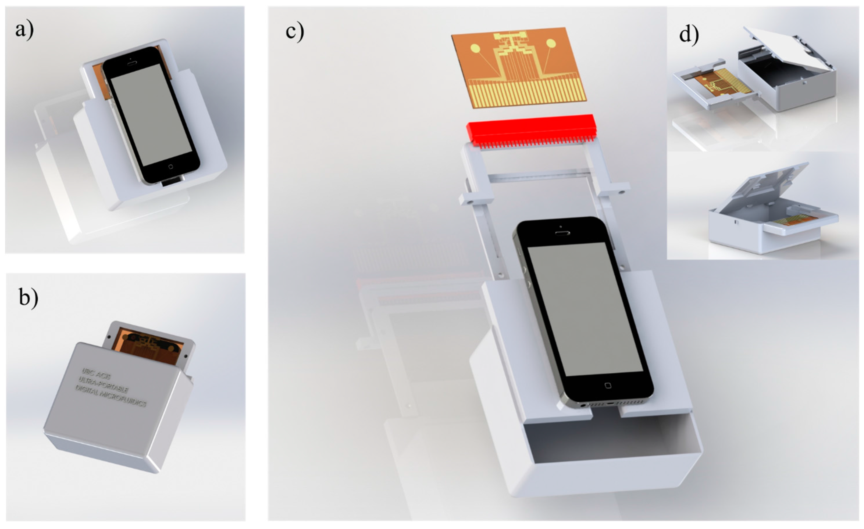
Figure 7.
A 3D CAD model (SolidWorks, Dassault Systemes, Vélizy-Villacoublay, France) for the modular DMF platform. (a) Front view showing how the phone is attached on top of the device, (b) back view, (c) exploded view showing the parts required for inserting the chip inside the device, and (d) shows how the DMF chip can be replaced and installed easily to the device.
For rapid prototyping and repeatable fabrication, the device is 3D printed with taking account of the portability, modularity, and smartphone compatibility according to the designed model shown in
Figure 7. The model is divided to three main parts: top plate holder, bottom plate holder, and peripheral electronic box. The bottom plate holder is designed to seat the DMF chip and connect the electrodes to the high voltage circuits directly. The top plate holder is designed to secure the top grounding indium tin oxide (ITO) plate on top of the bottom plate. The smartphone rests above the top plate holder where the thickness of the top plate is designed to adjust the focal distance between the smartphone camera and the droplets (1 cm approximate). Another 3D printed part is designed to enclose the required electrical circuits, electrodes’ pin connections, control and communication systems, and batteries. The top plate and bottom plate holders can be attached and detached easily from the circuits’ part. As a result, DMF chip part can be easily removed if further testing, analysis or post processing is needed directly on the chip. The measured total weight of the device is just 235 grams which demonstrates the device compactness and portability. The cost of the components used to construct the device are introduced in
Table 1 to estimate the total cost of the device. The whole device costs 62 US$ approximately.
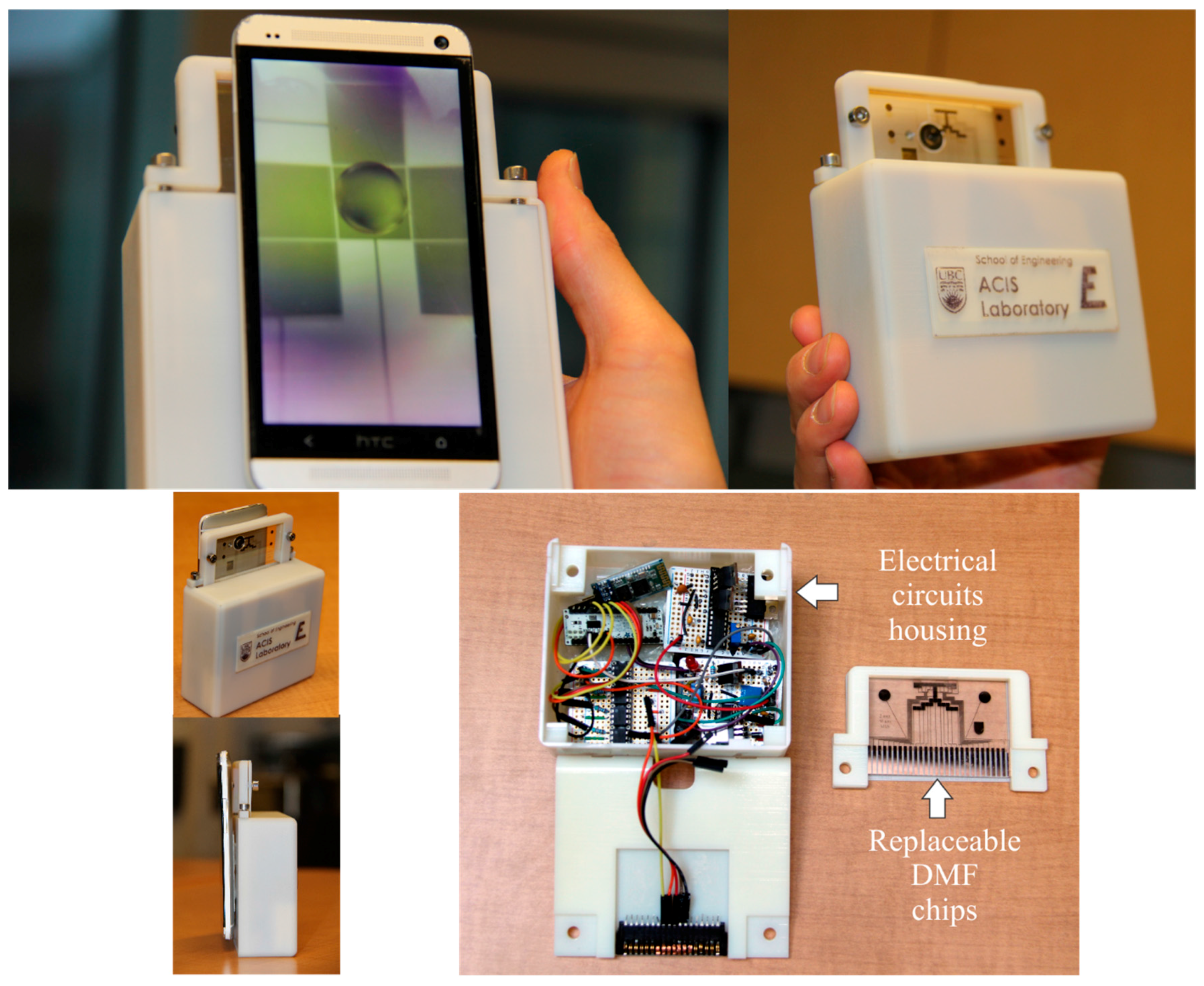
Figure 8.
The final prototyped portable DMF modular platform.
Figure 8.
The final prototyped portable DMF modular platform.
Table 1.
The cost of the components of the device.
Table 1.
The cost of the components of the device.
| Circuit | Components | Price in US$ |
|---|
| Boost DC to DC converter | 10 mH inductor (Murata Power Solutions inductor, 85 ma, Radial Leaded) | 0.6 |
| Vishay Siliconix, MOSFET IRFBG30 Transistor, N Channel, 3.1 A, 1 KV | 2.24 |
| Ceramic Capacitor 100PF | 0.015 |
| Through Hole Metal Film Resistor, 10 Mohm | 0.1 |
| 1N4937 Diode | 0.032 |
| Pulses generator circuit | Texas Instruments NE555P, Precision Timer, 500 kHZ, 16 V, DIP-8 | 0.45 |
| 2 capacitors and 2 resistors | 0.4 |
| Microcontroller | Arduino Micro | 19 |
| Bluetooth module | HC-06 Bluetooth module | 7 |
| Full bridge AC | 4 MOSFETS and a full bridge driver | 16 |
| Micro lens | Micro Phone lens | 15 |
| Total cost: 62 US$ |
Figure 8 shows the fabricated 3D printed and modular DMF platform assembly. This figure exhibits the portability of the device as it shows the device when it is hand-held. The DMF chip frames are designed to be easily inserted and ejected from the chip-to-board connection holder. A smartphone which is within the same size as the platform is used to monitor the system and detect any color changes of the droplets. Furthermore, the smartphone can be used to control the routing algorithm for droplet motion based on the post processing results.
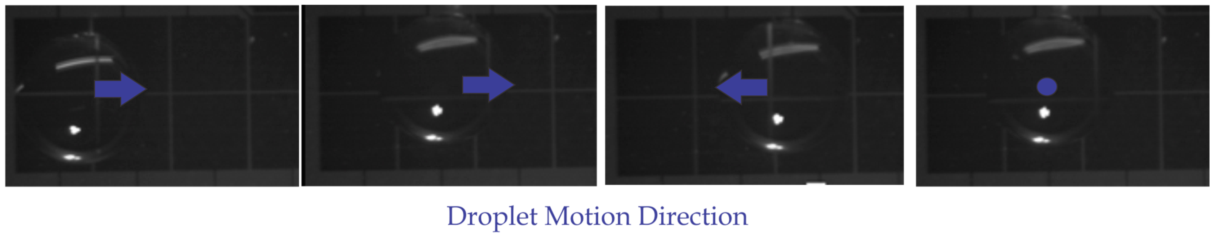
Figure 9 demonstrates a successful experiment for droplet motion where the droplet is transported using the electrical signal generated in
Figure 6. The smartphone is used to send the commands and control the motion sequence. A demonstrative video is added to the
supplementary data in order to show how the system works and how the smartphone can control the DMF operations using this device.
Figure 9.
The smartphone controls a preprogrammed droplet motion on top of a DMF chip.
Figure 9.
The smartphone controls a preprogrammed droplet motion on top of a DMF chip.
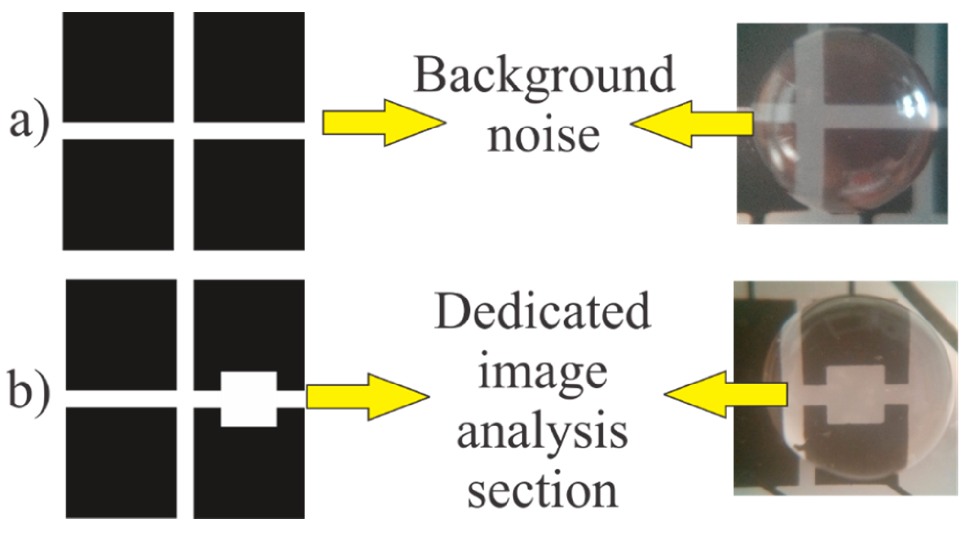
Several tests have been performed for assessing the capability of the system colorimetric assays on the DMF chip. Some applications exhibit slight color difference and some difficulties may arise when we try to distinguish between the droplets color using image analysis techniques while using the ordinary electrode design. Therefore, a new electrode design is proposed to detect the slight change in the color easily. This new design features a small window inside the electrode. The color is averaged on this window for having a consistent image analysis area on the chip. This design helps in eliminating the error that may arise from the electrodes reflection and the empty spacing between the electrodes when the color is averaged on the whole droplet footprint area. Therefore, the measurement on this window is not affected by the background colors. The difference between the ordinary electrode design and the new design with the dedicated image analysis section is demonstrated in
Figure 10.
Figure 10.
(a) Ordinary electrode design with background noise; (b) The new design with the dedicated image analysis section.
Figure 10.
(a) Ordinary electrode design with background noise; (b) The new design with the dedicated image analysis section.
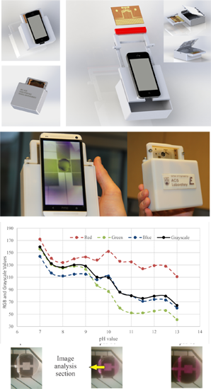
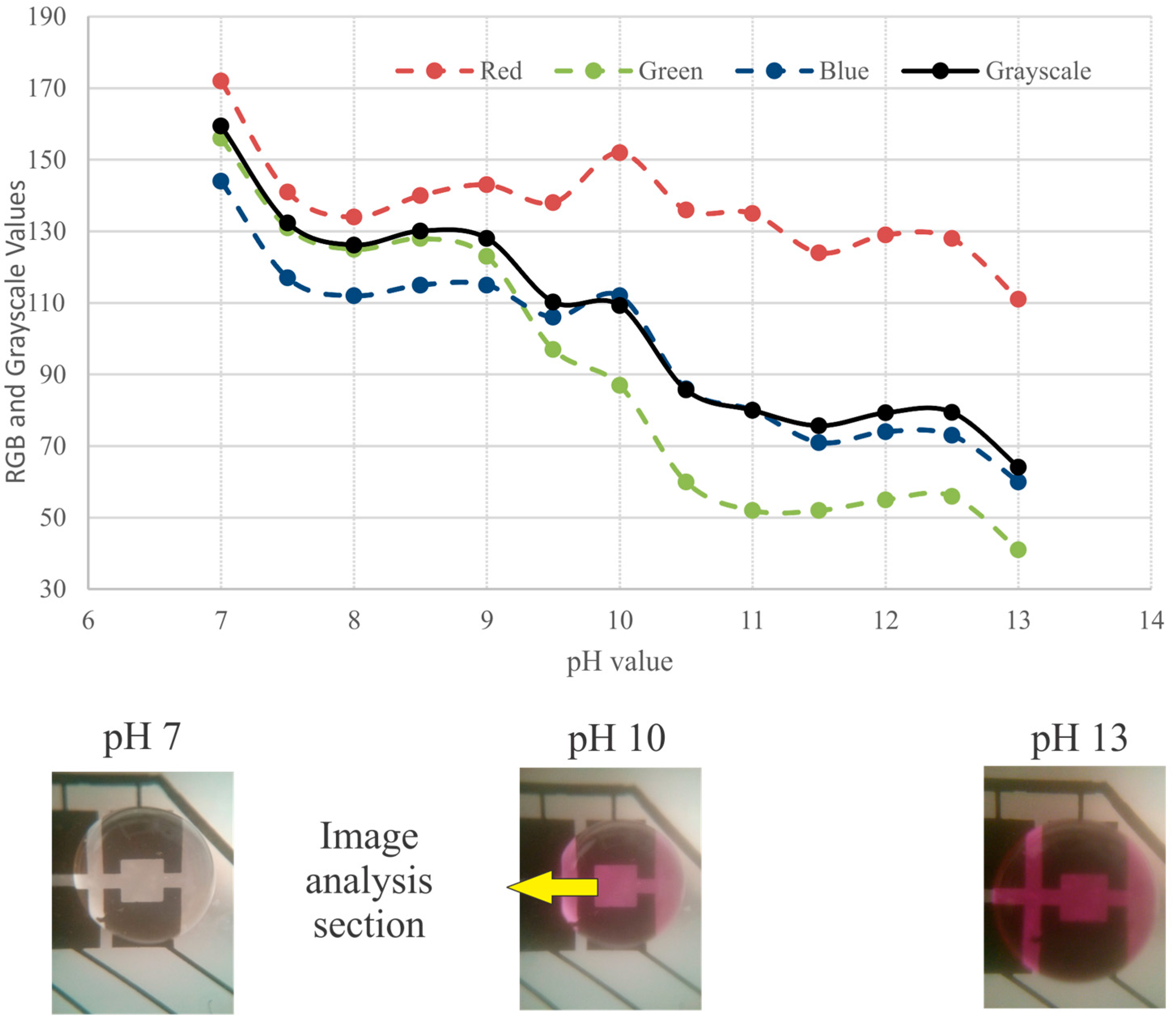
As a proof of concept application for the developed system, a basic colorimetric assay is performed. Solutions with phenolphthalein indicator at different pH values are used to assess the combined capability of the lens and the phone camera in detecting slight difference in color changes on DMF chips.
Figure 11 shows a droplet of pH 7 with transparent color on the left side and a droplet of pH 13 with pink color on the right hand side. The RGB values are measured by averaging the color on the image analysis section. Moreover, an additional grayscale indicator was calculated to determine the pH of the solution using the following equation [
46,
47]:
The RGB value combination determines the color of any object. However, those three color components do not have equal effect on color changes. As the color becomes darker we can notice that the red and the blue components show smaller changes compared to the significant changes in the green component. In addition, the eye sensitivity is a function of wavelength and is the greatest at a wavelength of about 5.6 × 10
−7 m (yellow-green) [
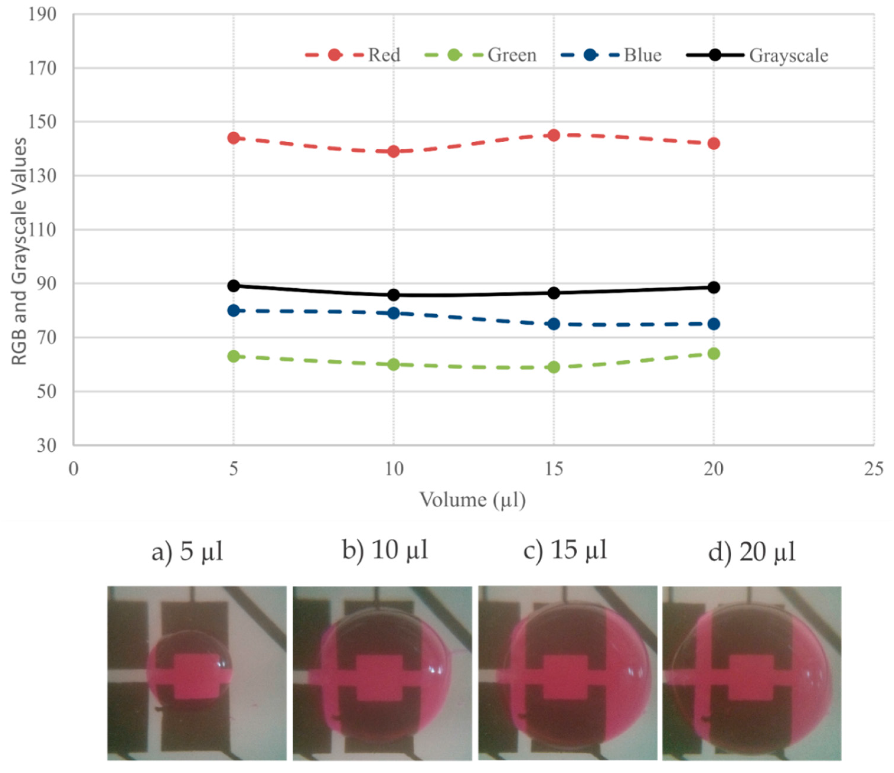
48]. Moreover, we can notice that the green color has the highest weight in the gray scale equation. Accordingly, the green component is the most affected component when the color becomes darker. Therefore, when there is significant color changes, the green component has a higher rate of change and it intersects the blue component when the color becomes darker. To investigate the effects of droplet volume on the color measurement, the averaged RGB values (over the designated region) were measured for different droplet volumes ranging from 5 to 20 μL. Shown in
Figure 12, no significant change was observed in the measurement.
Overall, the modular design, integration with smart phones, low (3D printing) fabrication cost, and cost effective battery-powered electrical components extend the implementation of DMF technology to a wider range of applications.
Figure 11.
The pH of the solution versus the color of the droplet in RGB and grayscale.
Figure 11.
The pH of the solution versus the color of the droplet in RGB and grayscale.
Figure 12.
The change in the volume of the droplet did not have a significant effect on the droplet color measurements when the droplet volume was varied from 5 to 20 µL.
Figure 12.
The change in the volume of the droplet did not have a significant effect on the droplet color measurements when the droplet volume was varied from 5 to 20 µL.


