Article

On-Chip Transportation and Measurement of Mechanical Characteristics of Oocytes in an Open Environment

Department of Mechanical Science and Engineering, Nagoya University, Furo-Cho, Chikusa-Ku, Nagoya 464-8601, Japan
*
Author to whom correspondence should be addressed.
Micromachines 2015, 6(5), 648-659; https://doi.org/10.3390/mi6050648
Submission received: 21 April 2015 / Revised: 11 May 2015 / Accepted: 19 May 2015 / Published: 22 May 2015
(This article belongs to the Collection Lab-on-a-Chip)

Abstract

:
We propose a system that transports oocytes and measures their mechanical characteristics in an open environment using a robot integrated microfluidic chip (chip). The cells are transported through a micropillar array in the chip, and their characteristics are measured by a mechanical probe and a force sensor. Because the chip has an open microchannel, important cells such as oocytes are easily introduced and collected without the risk for losing them. In addition, any bubbles trapped in the chip, which degrade the measurement precision, are easily removed. To transport the oocytes through the open microchannel, we adopt a transportation technique based on a vibration-induced flow. Under this flow, oocytes arrive at the measurement point, where their mechanical characteristics are determined. We demonstrate the introduction, transportation, measurement of mechanical characteristics, and collection of oocytes using this system.

1. Background

The mechanical characteristics of cells have been extensively researched [1,2,3,4,5,6,7] because, like traditional biochemical characteristics [8,9,10,11,12,13], they are thought to reflect cell quality. The cell mechanical characteristics, such as elasticity and viscoelasticity, are determined by measuring the cellular reaction force and cell deformation under an external force. The external force is conventionally applied by a micromanipulator or an atomic force microscope, and observed under an optical microscope. However, these cell manipulations must be skillfully performed by operators, and high-throughput highly repeatable measurements are difficult to achieve.
The above mentioned problem could be solved by measuring the cell mechanical characteristics on a chip. With recent micro–nano processing techniques and microfluidics technologies, on-chip measurements have become a feasible option. However, most research on this topic has involved mechanical stimulation of cells by a fluid force applied in a closed microchannel [14,15]. Because no mechanical sensors are employed, these methods cannot reliably quantify the cell mechanical characteristics.
On the other hand, our group has proposed a robot integrated microfluidic chip (chip) for measuring the cell mechanical characteristics [16,17]. For quantitative measurement, the chip contains a mechanical probe and a force sensor. The target cell is transported to the measurement point under a fluid flow controlled in the microchannel. Having reached the measurement point, the cell is subjected to an external force and its reaction force is measured by the force sensor, as shown in Figure 1. This mechanism enables continuous and quantitative measurement of the mechanical characteristics of cells.
Figure 1. On-chip measurement of mechanical characteristics of oocytes.
Micromachines 06 00648 g001
However, the closed microchannel is problematic for several reasons. For instance, bubbles often become trapped in the movable part of the force sensor. If these bubbles contact the force sensor, their surface tension adds to the force detected by the sensor, elevating the apparent reaction force of the oocytes. The compressive property of the bubbles also destabilizes the fluid control. Furthermore, the closed microchannel requires complex connection of the microfluidic channel to the external pump, such as tube connections. Thus, target cells can be easily lost at the connection part and difficult to be introduced and collected. Cell loss is a serious problem when measuring important cells, such as oocytes. To achieve a bubble-free system in which cells are easily introduced and collected, we employ an open microchannel for measuring the cell mechanical characteristics.
Cells in an open microchannel can be manipulated by optical tweezers, surface acoustic waves, or dielectrophoresis. Optical tweezers [18,19] can manipulate a single cell with high positional accuracy, but offer small trapping force, which limits their use to small cells. Surface acoustic wave techniques [20] are difficult to integrate with other functional devices (such as mechanical probes and sensors) on a piezoelectric substrate. Dielectrophoresis [21,22] can manipulate cells in an open microchannel, but requires multiple independently controlled electrodes, which complicates the fabrication process and control system.
On the other hand, large cells can be transported by a vibration-induced flow technique [23]. Furthermore, an on-chip transportation functionality is obtained merely by fabricating micropillars on the chip. Therefore, by using vibration-induced flow as a cell transport mechanism through the chip, we can measure the cell mechanical characteristics without bubble formation or cell loss.
To this end, we construct a transportation and measurement system for mouse oocytes, and demonstrate the introduction, transportation, measurement of mechanical characteristics and collection in this study. Mouse has been widely used as the experimental animal because it shares a high degree of homology with human gene. According to the study of Sun et al. [4], there is a difference between young mouse oocyte and old mouse oocyte in terms of their reaction force. Additionally, in Reference [13], it is reported that the fertility decreases with aging. Thus, it is thought that there are some relationships between the mechanical characteristics of mouse oocyte and the qualities (e.g., fertility), and we choose mouse oocyte as a target.

2. Concept

This paper proposes a system for transporting oocytes through a chip with an open microchannel, and measuring their mechanical characteristics. The system is conceptualized in Figure 2. The transportation and measurement is performed in four steps:
(i)
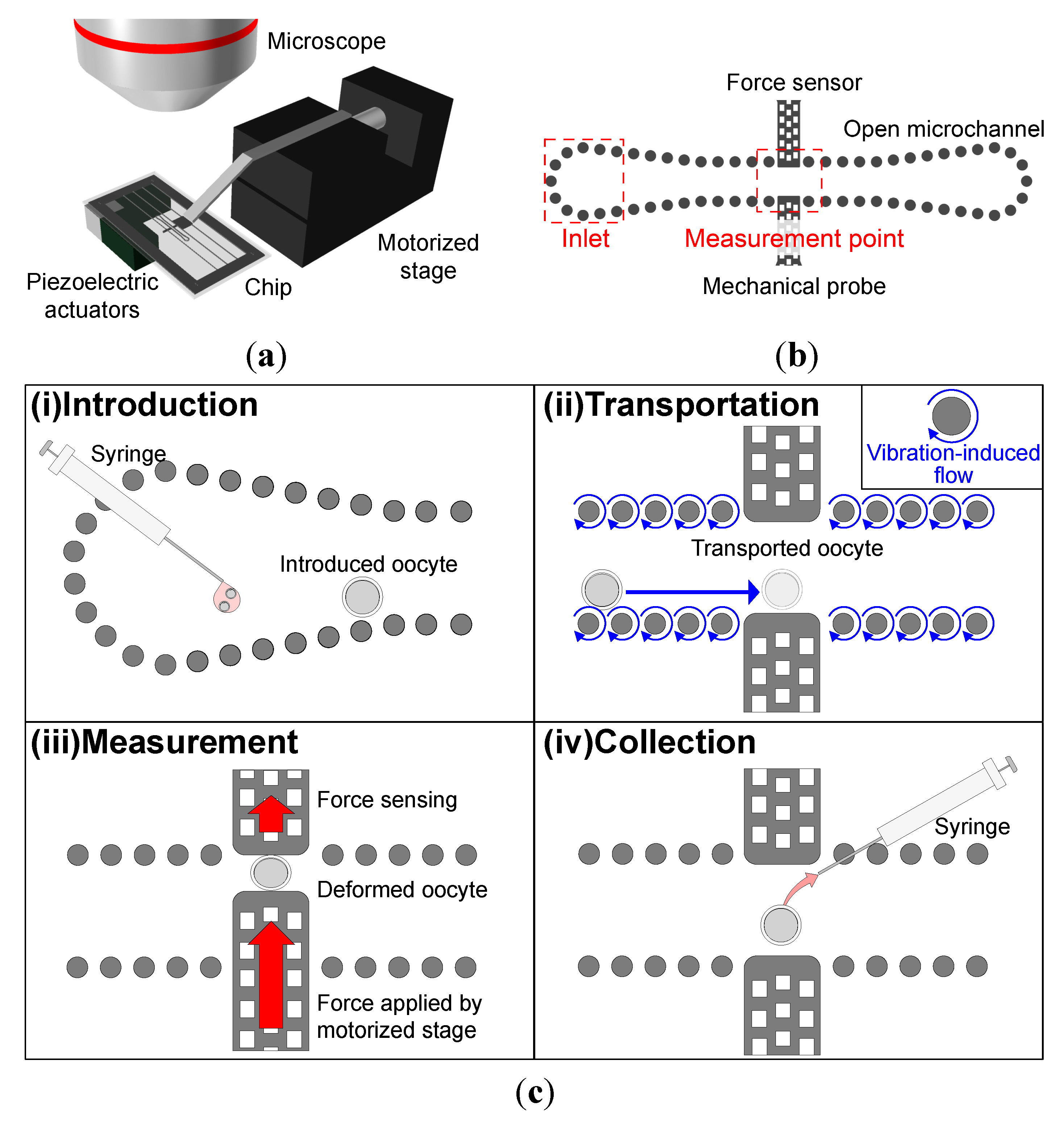
Introduction: An oocyte is introduced to the chip. By virtue of the open microchannel, oocytes can be introduced by merely dropping the oocyte-containing culture medium into the channel.
(ii)
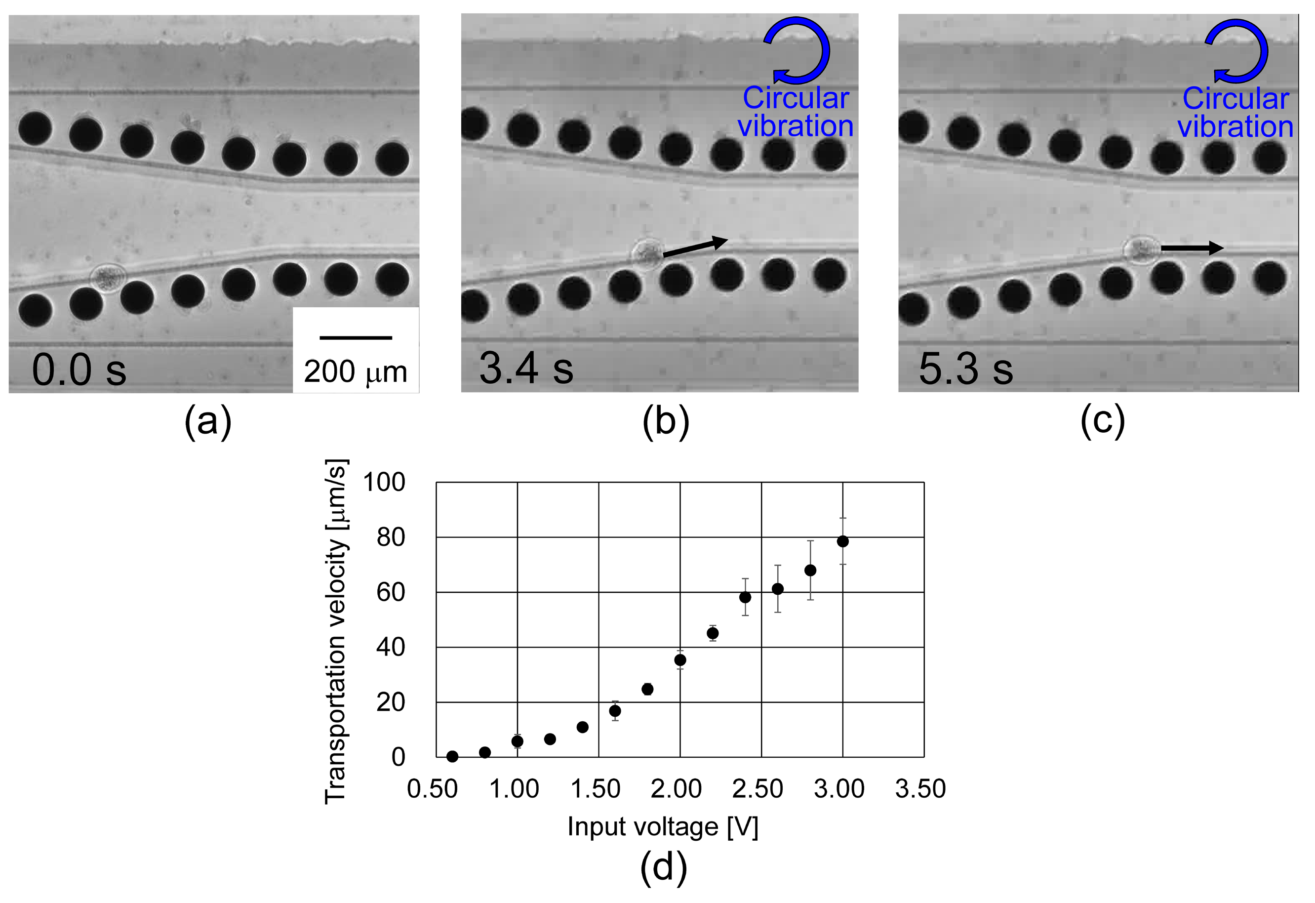
Transportation: By applying circular vibration to the chip, local flow can be generated around each micropillar. Thus, we can transport the oocyte by patterning micropillar array on the chip and applying circular vibration to the chip. We can transport the oocyte along micropillar array towards the measurement point by a vibration-induced flow. By stopping the circular vibration when the oocyte reaches the measurement point, we can introduce the oocyte to the measurement point.
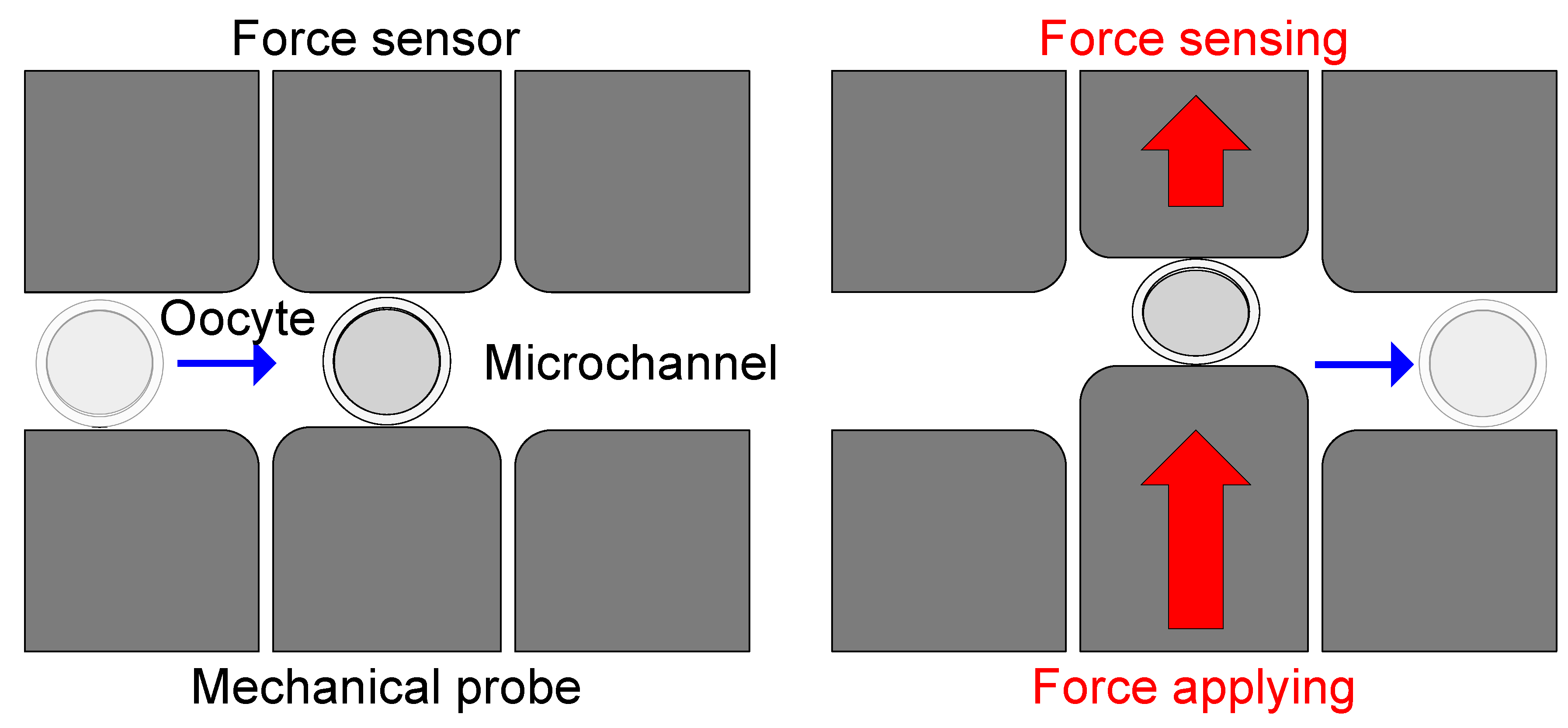
(iii)
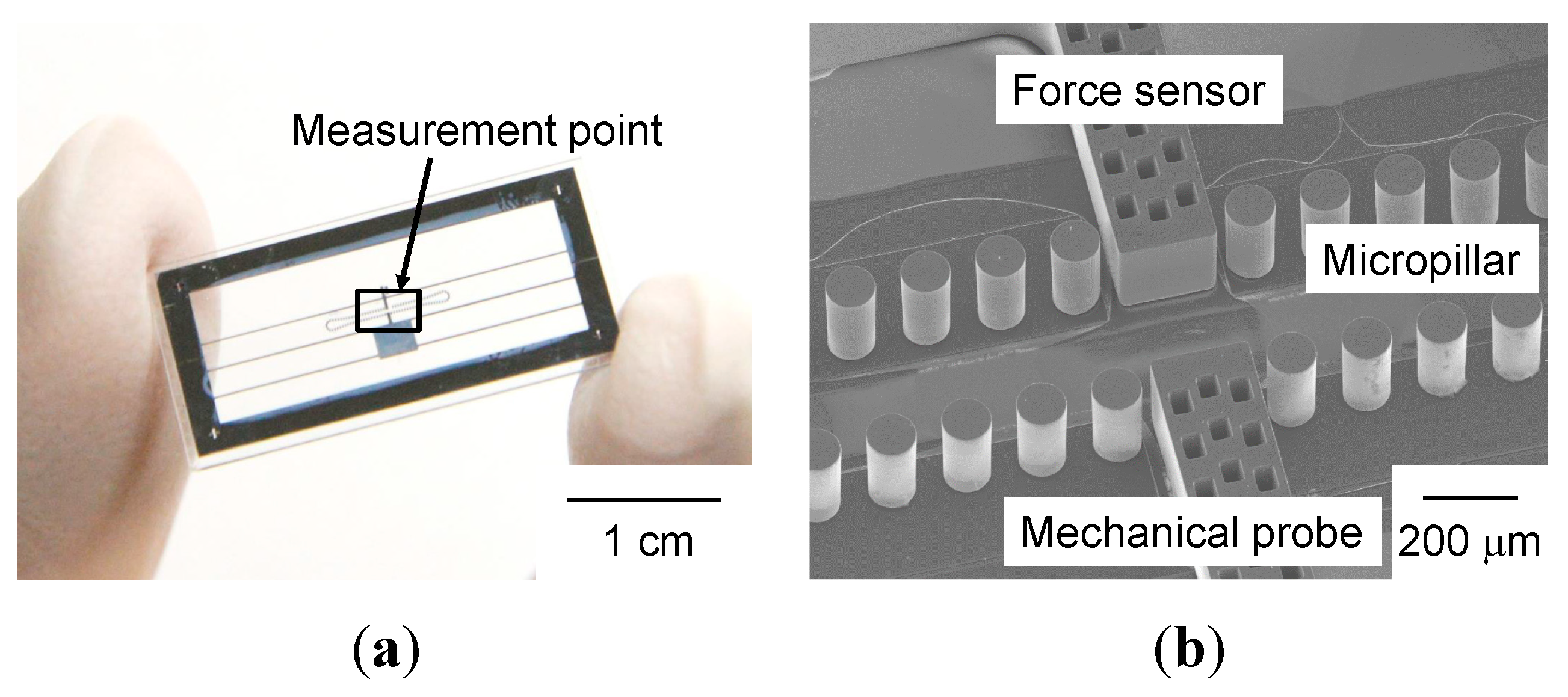
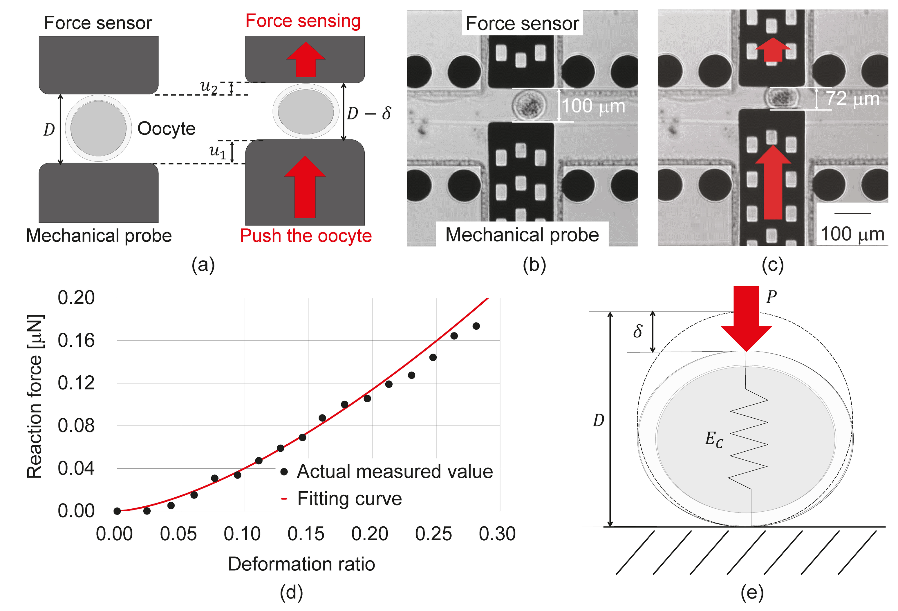
Measurement: A mechanical probe and a force sensor are installed at the measurement point. The mechanical probe is driven by an external single-axis motorized stage, and the probe pushes the oocyte toward the force sensor. The mechanical characteristics of the oocyte are calculated from the displacement of the force sensor and the oocyte deformation.
(iv)
Collection: The oocyte is collected after measurement. Similar to step (i), the oocyte can be collected by aspirating it with a syringe.
Figure 2. Concept of on-chip transportation and measurement of the mechanical characteristics of oocyte in an open-environment: (a) Schematic of the system setup; (b) schematic of the chip design; (c) procedure of proposed measurement method.
Micromachines 06 00648 g002

3. Experimental Section
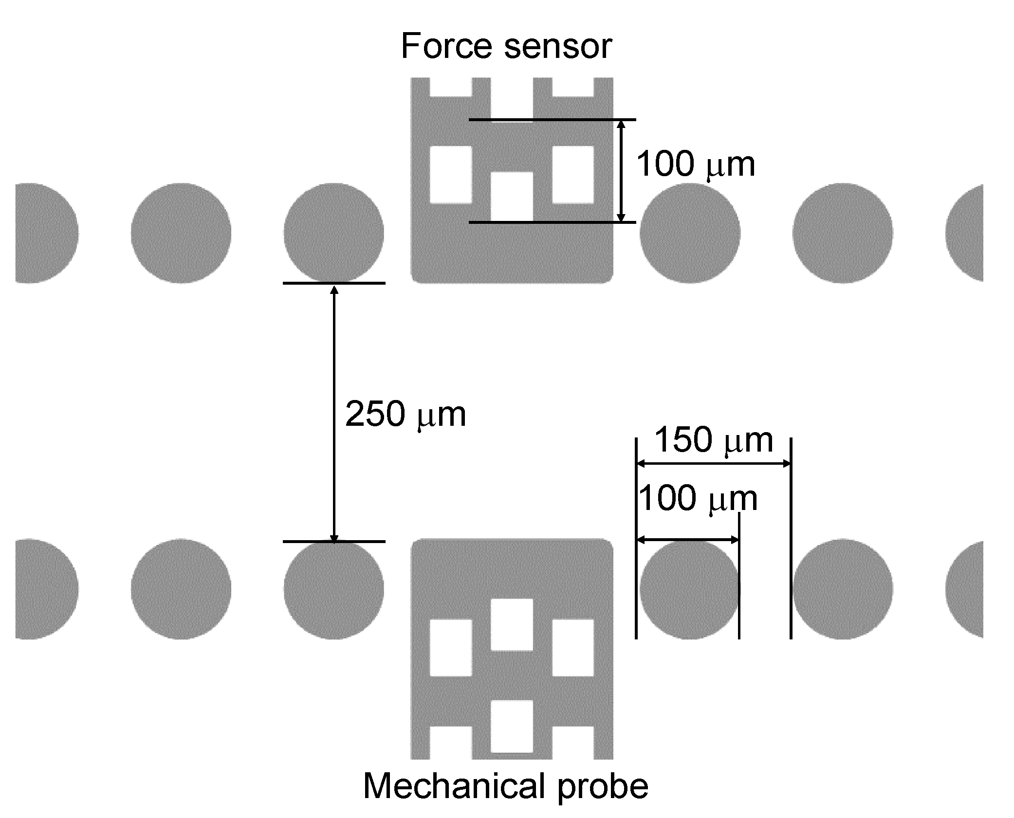
3.1. Chip Design

Figure 3 shows the chip design. The oocyte is transported through a micropillar array as shown in Figure 2b, based on a vibration-induced flow technique [23]. The measurement point contains a cantilever-type force sensor and a mechanical probe. Transported oocyte is pushed to the force sensor by the mechanical probe and reaction force of the oocyte is measured from the displacement of the sensor. Mechanical characteristics of the oocyte can be calculated from the reaction force and the deformation amount of the oocyte.
The displacements of the force sensor and the mechanical probe are measured by the sampling moiré method [24,25]. We make grating structures on the force sensor and the mechanical probe and capture the images of the grating patterns by CCD (Charge-Coupled Device) camera. By down-sampling the captured images and interpolating them, the images of the moiré fringe are obtained. The intensity of the moiré fringe is expressed as:
I k = I a cos ( φ ( x ) + 2 π k N ) + I b
where I a represents the amplitude of the optical intensity on the gratings, I b represents the background intensity, φ represents the phase of the moiré fringe, x represents the horizontal position of the sampling point, k represents the index of the phase shift on the moiré fringe, and N is the maximum value of the index k , respectively. The phase distribution of the fringe is obtained by applying Discrete Fourier Transformation to Equation (1), which is expressed as:
φ = tan 1 { k I k sin ( 2 π k N ) k I k cos ( 2 π k N ) }
and finally the displacement u is expressed as:
u = Δ φ 2 π p
where p represents the grating pitch. Thus, by analyzing the phase of the moiré fringe, we can measure the displacement of the force sensor and the mechanical probe when they are moved.
In this study, we determine the design values as follows. Each micropillar is 100 μm in diameter and 200 μm high. The micropillars are pitched at 150 μm and the channel width is 250 μm. The sensitivity of the force sensor that measures the oocyte mechanical characteristics is 6.79 × 10⁻² N/m. The pitch of the grating structure is 100 μm.
Figure 3. Design of robot integrated microfluidic chip.
Micromachines 06 00648 g003

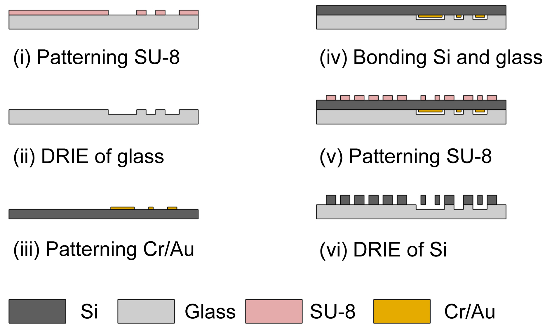
3.2. Chip Fabrication
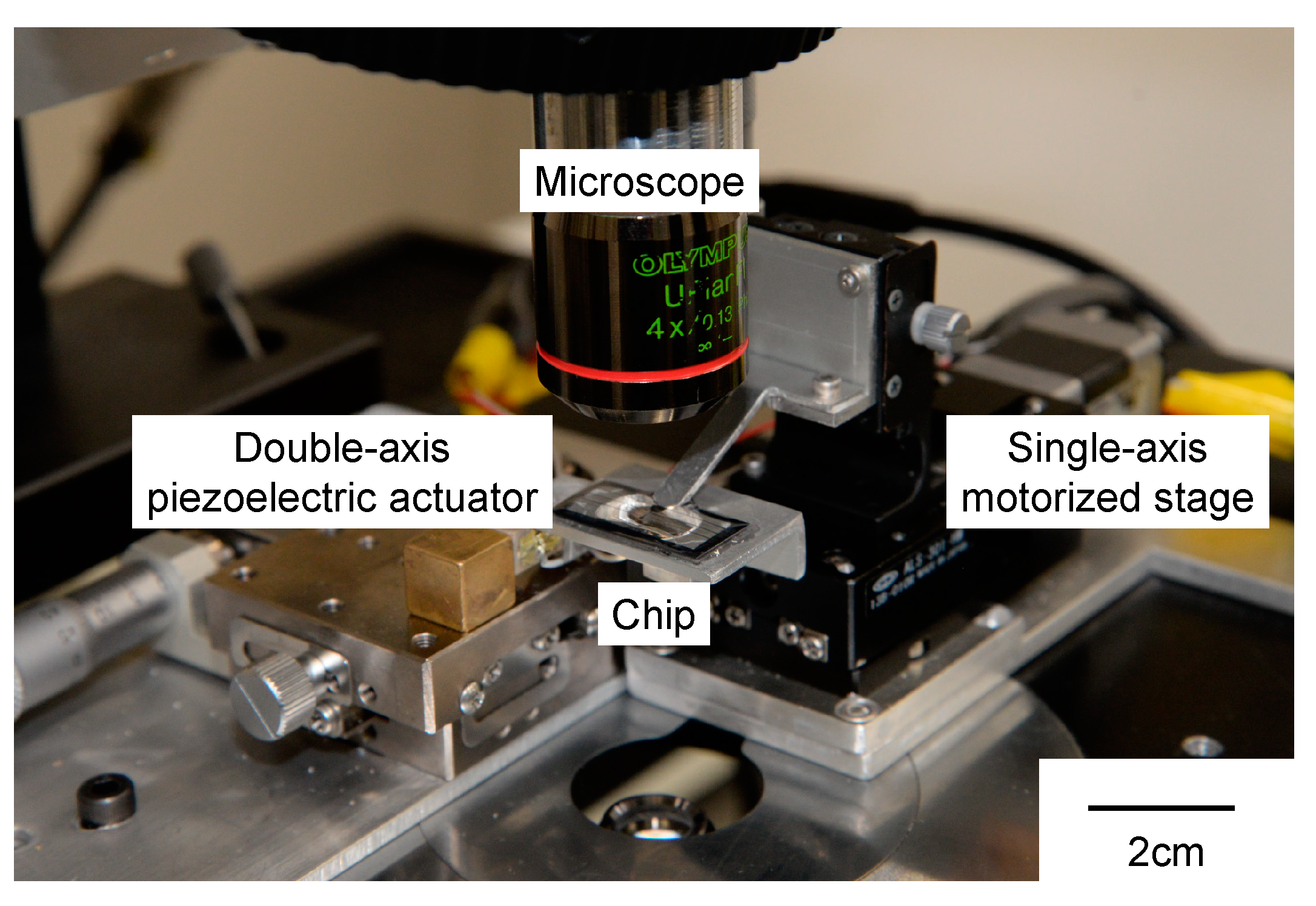
The chip fabrication process is shown in Figure 4. If the mechanical probe or force sensor exerts significant friction against the glass substrate, the mechanical characteristics of the oocyte are difficult to measure. To achieve the necessary friction reduction, we specify a clearance on the glass substrate. During step (iii) of the fabrication process, a Cr/Au layer is patterned on the Si substrate as the etch-stop layer. This layer is critically important for fabricating the micropillar array, mechanical probe, and force sensor without overetching during step (vi) of the fabrication (see Figure 4).
Panels (a) and (b) of Figure 5 present a photograph of a fabricated chip and an SEM image of the measurement point, respectively.
Figure 4. Fabrication process of microfluidic chip: (i) To make a clearance pattern between glass substrate and movable part of Si layer, SU-8 is patterned onto a glass substrate as the etching mask for reactive-ion etching (RIE); (ii) RIE of the glass substrate is performed to a depth of 10 μm; (iii) A Cr/Au layer is patterned by lift off process as an etch stop layer. Cr/Au is deposited by sputtering; (iv) The clearance-patterned glass substrate is bonded to the Cr/Au patterned Si substrate by plasma activated bonding. Both substrates are treated with O2 and N2 plasma prior to bonding. After that, these substrates are bonded together and applied 700 V DC voltage; (v) SU-8 is patterned on the Si substrate as the etching mask for deep RIE (DRIE); (vi) The micropillar array, mechanical probe and force sensor are fabricated by DRIE of the Si substrate, followed by etching of the Cr/Au layer.
Micromachines 06 00648 g004
Figure 5. A fabricated chip: (a) Photograph of chip; (b) scanning electron microscope (SEM) image of the measurement point.
Micromachines 06 00648 g005

3.3. System Setup

Figure 6 presents the overall experimental setup. Two horizontally positioned piezoelectric actuators (PAC166J, Nihon Ceratec Co., Ltd., Miyagi, Japan) are connected to a function generator (WF1974, NF Corporation, Kanagawa, Japan) through a voltage amplifier (Four-channel high-voltage wideband amplifier 9400, gain x50, TOYO Corporation, Tokyo, Japan). The function generator applies sinusoidal input signals with 90° or 270° phase difference to the double-axis piezoelectric actuator. This actuator is connected to the chip through a jig with adhesive. A vibration-induced flow is generated by applying circular vibration to the chip. The mechanical probe integrated in the chip is driven by an external single-axis motorized stage (ALS-301-HM, Chuo Precision Industrial Co., Ltd., Tokyo, Japan) through a jig. The single-axis motorized stage is equipped with a stepping motor. The transportation and measurement process is observed by using the optical microscope.
Figure 6. Experimental setup.
Micromachines 06 00648 g006

3.4. Sample Cell Preparation

Sample mouse oocytes were purchased from Japan SLC Inc. (Shizuoka, Japan). Immediately prior to experiment, the oocytes were cryopreserved and thawed following the protocols of Reference [26]. In all experiments, we used Medium 199 (11150-059, Life Technologies Japan Ltd., Tokyo, Japan) for oocyte culture medium.

4. Results

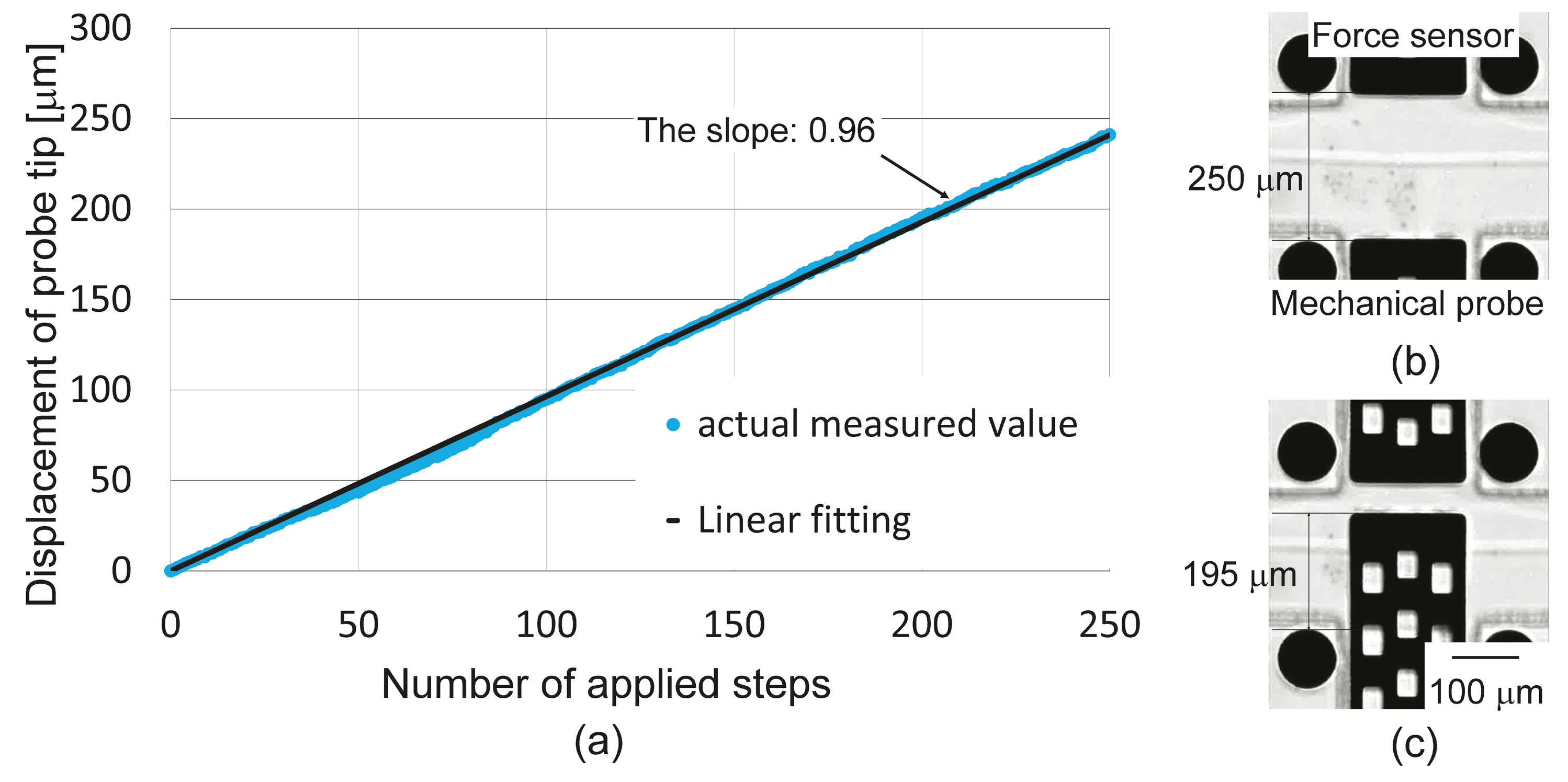
4.1. Evaluation of Mechanical Probe

For precise measurement of the mechanical characteristics of oocytes, we evaluated the positioning accuracy of the mechanical probe. Figure 7a plots the relationship between the number of steps applied to the stepping motor and the displacement of the probe tip. The mechanical probe was driven through 250 steps of the stepping motor. In Figure 7a, the blue dots represent the measured tip positions, and the black line represents their linear fitting through the point (0, 0). The positioning accuracy of the mechanical probe is 0.96 μm/step.
Figure 7. Performance evaluation of mechanical probe: (a) Displacement of probe tip vs. step count; (b) original probe position; (c) position after 200 steps of the stepping motor.
Micromachines 06 00648 g007

4.2. Introduction of Oocytes

An oocyte was introduced to the chip through the PFA (polytetrafluoroethylene) tube, as shown in Figure 8a,b. The PFA tube is connected to the syringe, and the flow is controlled by manually handling the plunger. The oocyte was not lost when the tube was removed from the chip (Figure 8c).
Figure 8. Demonstration of oocyte introduction: (a) Before introduction; (b) after introduction; (c) after removal of the PFA tube.
Micromachines 06 00648 g008

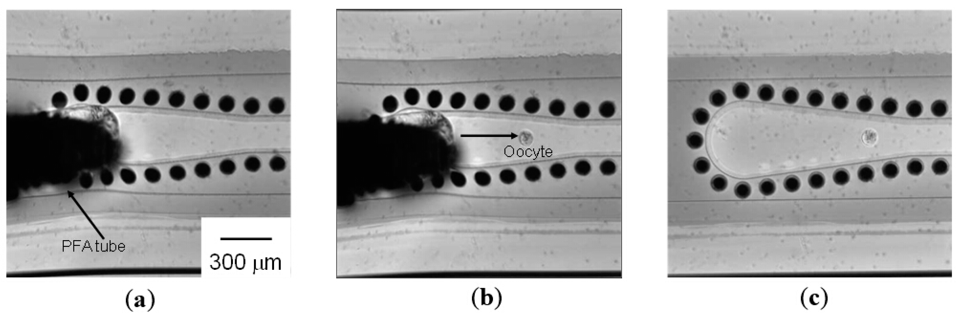
4.3. Transportation of Oocytes

Once the oocyte had been introduced to the channel, it was transported under a circular vibration applied to the chip. The transportation by the vibration-induced flow is demonstrated in panels (a)–(c) of Figure 9. The applied frequency was 300 Hz. The relationship between the input voltage from the function generator and the oocyte transportation velocity is plotted in Figure 9d. The average diameter of four sample oocytes was approximately 108 μm (with a standard deviation of 2 μm). The black dots in Figure 9d represent the average transportation velocity at each input voltage, and the error bars represent the variation. The transportation velocity can be varied from 0.3 μm/s to 78 μm/s by changing the applied voltage.
Figure 9. Demonstration of oocyte transportation under a vibration-induced flow, and the experimental result: Microscopic images (a) before application of the circular vibration; (b) after 3.4 s; (c) after 5.3 s; (d) transportation velocity vs. input voltage.
Micromachines 06 00648 g009

4.4. Measurement of Mechanical Characteristics of Oocytes

Once the target oocyte had reached to the measurement point, its mechanical characteristics were measured. Firstly, we actuated the mechanical probe towards the oocyte and stopped when it contacted to the oocyte. Then, we repeatedly actuated the probe with 1.92 μm displacement that was equivalent to 2 steps of the stepping motor and waited 5-s for each actuation. We applied a total of 38.4 μm displacement from the contact point for each measurement. The schematic of the measurement is shown in Figure 10a. D represents the original diameter of the oocyte, δ represents the deformation amount of oocyte, u 1 represents the applied displacement of the mechanical probe (38.4 μm in this study) and u 2 represents the displacement of the force sensor.
This experiment was performed on a mouse oocyte that had been thawed and cultured for 1 h. A typical measurement result is photographed in Figure 10. We measured the reaction force of the oocyte from the displacement of the force sensor u 2 and the deformation amount of the oocyte   δ . Figure 10d plots the relationship between the deformation ratio and the oocyte reaction force. The black points represent the measured values. In this research, the oocyte was modeled as a sphere with a spring element. Under this assumption, we adopted Hertzian contact theory and calculated the Young’s modulus EC of the oocyte [16,27]. The reaction force was then expressed as:
P =   4 ( D / 2 ) 1 / 2 3 · E C 1 ν 2 ( δ / 2 ) 3 / 2
where P and denote the reaction force. E C represents the Young’s modulus, ν represents the Poisson’s ratio. The Poisson’s ratio of a spherical object composed of incompressible fluidic material is 0.5. The Young’s modulus of the oocyte photographed in Figure 10 was estimated as 203.2 Pa. The red line in Figure 10d is the reaction force predicted by Hertzian contact theory.
Figure 10. Mechanical characterization of oocytes: (a) Concept of measurement; (b) photograph taken before measurement; (c) photograph taken during measurement; (d) deformation ratio vs. reaction force; (e) model of Hertzian contact theory.
Micromachines 06 00648 g010
The above measurements were performed on nine oocytes, and the results are summarized in Table 1.
Table 1. Experimental results.
Sample No.Diameter (μm)Ec (Pa)
1100203.2
296404.6
397367.5
4108222.0
596381.8
699224.2
797406.0
897332.8
9102281.4

4.5. Oocyte Viability Evaluation

All of the measured oocytes were collected, cultivated for approximately 5 h, and subjected to a viability analysis. The viability of the cultivated oocytes was assessed by using the LIVE/DEAD Viability Kit (L-3224, Life Technologies Japan Ltd.). Seventy eight percent of the oocytes were alive at the end of the cultivation period, comparable to the viability of control samples (82%; N = 11). Thus, we conclude that the proposed measurement system causes no significant damage to the cells.

5. Conclusions

We have proposed a system for transporting oocytes and measuring their mechanical characteristics in a robot integrated microfluidic chip. The proposed system solved the intractable problems of conventional closed-chip systems (bubble formations, difficult cell introduction, and cell loss prior to collection). Furthermore, we demonstrated the introduction, transportation, measurements of mechanical characteristics, and collection of oocytes in the proposed system. The absence of bubbles and retrieval of oocytes after the measurement were confirmed in the demonstration. The proposed system enables post-measurement analysis, which is important for relating the mechanical characteristics and biological properties, such as fertility or development rate with long-term incubation. It will contribute to the quality evaluation of oocytes for clinical fertility treatment and basic biological research.

Acknowledgments

This work was supported by JSPS Grant-in-Aid for Challenging Exploratory Research (15K13909).

Author Contributions

Kou Nakahara, Shinya Sakuma, Takeshi Hayakawa and Fumihito Arai are equally contributed to this work. Kou Nakahara, Shinya Sakuma, Takeshi Hayakawa and Fumihito Arai performed conception and design of the study, collection of data, analysis and interpretation of data, drafting of the manuscript, and critical revision of the manuscript for important intellectual content.

Supplementary Materials

The video shows the demonstration of the transportation and measurement of mechanical characteristics of oocyte, as described in Section 4.3 and Section 4.4. Supplementary materials can be accessed at: https://www.mdpi.com/2072-666X/6/5/648/s1.

Conflicts of Interest

The authors declare no conflict of interest.

References

  1. Sun, Y.; Wan, K.-T.; Roberts, K.P.; Bischof, J.C.; Nelson, B.J. Mechanical property characterization of mouse zona pellucida. IEEE Trans. Nanobiosci. 2003, 2, 279–286. [Google Scholar] [CrossRef]
  2. Jaasma, M.J.; Jackson, W.M.; Keaveny, T.M. Measurement and characterization of whole-cell mechanical behavior. Ann. Biomed. Eng. 2006, 34, 748–758. [Google Scholar] [CrossRef] [PubMed]
  3. Wacogne, B.; Pieralli, C.; Roux, C.; Gharbi, T. Measuring the mechanical behavior of human oocytes with a very simple SU-8 micro-tool. Biomed. Microdevices. 2008, 10, 411–419. [Google Scholar] [CrossRef] [PubMed]
  4. Liu, X.; Fernandes, R.; Jurisicova, A.; Casper, R.F.; Sun, Y. In situ measurement of mechanical characteristics of mouse oocytes using a cell holding device. Lab Chip 2010, 10, 2154–2161. [Google Scholar] [CrossRef] [PubMed]
  5. Khalilian, M.; Navidbakhsh, M.; Valojerdi, M.R.; Chizari, M.; Yazdi, P.E. Estimating young’s modulus of zona pellucida by micropipette aspiration in combination with theoretical models of ovum. J. R. Soc. Interface 2010, 7, 687–694. [Google Scholar] [CrossRef] [PubMed]
  6. Murayama, Y.; Mizuno, J.; Kamakura, H.; Fueta, Y.; Nakamura, H.; Akaishi, K.; Anzai, K.; Watanabe, A.; Inui, H.; Omata, S. Mouse zona pellucida dynamically changes its elasticity during oocyte maturation, fertilization and early embryo development. Hum. Cell 2006, 19, 119–125. [Google Scholar] [CrossRef] [PubMed]
  7. Sun, Y.; Nelson, B.J.; Greminger, M.A. Investigating protein structure change in the zona pellucida with a microrobotic system. Int. J. Robot. Res. 2005, 24, 211–218. [Google Scholar] [CrossRef]
  8. Lyons, A.B. Analysing cell division in vivo and in vitro using flow cytometric measurement of CFSE dye dilusion. J. Immunol. Methods 2000, 243, 147–154. [Google Scholar] [CrossRef] [PubMed]
  9. Cillo, F.; Brevini, A.L.; Antonini, S.; Paffioni, A.; Ragni, G.; Gandolfi, F. Assocaiation between human oocyte developmental competence and expression levels of some cumulus genes. Reproduction 2007, 134, 645–650. [Google Scholar] [CrossRef] [PubMed]
  10. Beer, D.D.; Stoodley, P.; Lewandowski, Z. Measurement of local diffusion coefficients in biofilms by microinjection and confocal microscopy. Biotechnol. Bioeng. 1997, 53, 151–158. [Google Scholar] [CrossRef] [PubMed]
  11. Lyng, H.; Haraldseth, O.; Rofstad, E.K. Measurement of cell density and necrotic fraction in human melanoma xenografts by diffusion weighted magnetic resonance imaging. Magnet Reson. Med. 2000, 43, 828–836. [Google Scholar] [CrossRef]
  12. Rizos, D.; Ward, F.; Duffy, P.; Boland, M.P.; Lonergan, P. Consequences of bovine oocyte maturation, fertilization or early embryo development in vitro versus in vivo: Implications for blastocyst yield and blastocyst quality. Mol. Reprod. Dev. 2002, 61, 234–248. [Google Scholar] [CrossRef] [PubMed]
  13. Fujino, Y.; Ozaki, K.; Yamamasu, S.; Ito, F.; Matsuoka, I.; Hayashi, E.; Nakamura, H.; Ogita, S.; Sato, E.; Inoue, M. DNA fragmentation of oocytes in aged mice. Hum. Reprod. 1996, 11, 1480–1483. [Google Scholar] [CrossRef] [PubMed]
  14. Sakuma, S.; Kuroda, K.; Tsai, C.-H.D.; Fukui, W.; Arai, F.; Kaneko, M. Red blood cell fatigue evaluation based on the close-encountering point between extensibility and recoverability. Lab. Chip 2014, 14, 1135–1141. [Google Scholar] [CrossRef] [PubMed]
  15. Gossett, D.R.; Tse, H.T.K.; Lee, S.A.; Ying, Y.; Lindgren, A.G.; Yang, O.O.; Rao, J.; Clark, A.T.; Carlo, D.D. Hydrodynamic stretching of single cells for large population mechanical phenotyping. Proc. Natl. Acad. Sci. USA 2012, 109, 7630–7635. [Google Scholar] [CrossRef] [PubMed]
  16. Sakuma, S.; Turan, B.; Arai, F. High throughput measurement of mechanical characteristics of oocyte using robot integrated microfluidic chip. In Proceedings of 2013 IEEE/RSJ International Conference on Intelligent Robots and Systems (IROS), Tokyo, Japan, 3–7 November 2013; pp. 2047–2052.
  17. Sakuma, S.; Arai, F. Cellular force measurement using a nanometric-probe-integrated microfluidic chip with a displacement reduction mechanism. J. R. M. 2013, 25, 277–284. [Google Scholar]
  18. Ashkin, A.; Dziedzic, J.M. Optical trapping and manipulation of viruses and bacteria. Science 1987, 235, 1517–1520. [Google Scholar] [CrossRef] [PubMed]
  19. Ashkin, A.; Dziedzic, J.M.; Yamane, T. Optical trapping and manipulation of single cells using infrared laser beams. Nature 1987, 330, 769–771. [Google Scholar] [CrossRef] [PubMed]
  20. Yeo, L.Y.; Friend, J.R. Ultrafast microfluidics using surface acoustic waves. Biomicrofluidics 2009, 3, 012002. [Google Scholar] [CrossRef]
  21. Voldman, J.; Gray, M.L.; Toner, M.; Schmidt, M.A. A microfabrication-based dynamic array cytometer. Anal. Chem. 2002, 74, 3984–3990. [Google Scholar] [CrossRef] [PubMed]
  22. Chiou, P.Y.; Ohta, A.T.; Wu, M.C. Massively parallel manipulation of single cells and microparticles using optical images. Nature 2005, 436, 370–372. [Google Scholar] [CrossRef] [PubMed]
  23. Hayakawa, T.; Sakuma, S.; Fukuhara, T.; Yokoyama, Y.; Arai, F. A single cell extraction chip using vibration-induced whirling flow and a thermo-responsive gel pattern. Micromachines 2014, 5, 681–696. [Google Scholar] [CrossRef]
  24. Sugiura, H.; Sakuma, S.; Kaneko, M.; Arai, F. On-chip measurement of cellular mechanical properties using moiré fringe. In Proceedings of 2015 IEEE International Conference on Robotics and Automation (ICRA), Seattle, WA, USA, 26–30 May 2015.
  25. Ri, S.; Fujigaki, M.; Morimoto, Y. Sampling moiré method for accurate small deformation distribution measurement. Exp. Mech. 2010, 50, 501–508. [Google Scholar] [CrossRef]
  26. Nakao, K.; Nakagata, N.; Katsuki, M. Simple and efficient vitrification procedure for cryopreservation of mouse embryos. Exp. Anim. 1997, 46, 231–234. [Google Scholar] [CrossRef] [PubMed]
  27. Bacabac, R.G.; Mizuno, D.; Schmidt, C.F.; MacKintosh, F.C.; van Loon, J.J.; Klein-Nulend, J.; Smit, T.H. Round versus flat: Bone cell morphology, elasticity, and mechanosensing. J. Appl. Biomech. 2008, 41, 1590–1598. [Google Scholar] [CrossRef]

