Article

Design and Implementation of a Bionic Mimosa Robot with Delicate Leaf Swing Behavior

Department of Biomechatronics Engineering, National Pingtung University of Science and Technology, No. 1 Shuefu Road, Neipu, Pingtung County 91201, Taiwan
*
Author to whom correspondence should be addressed.
Micromachines 2015, 6(1), 42-62; https://doi.org/10.3390/mi6010042
Submission received: 6 September 2014 / Accepted: 5 December 2014 / Published: 23 December 2014
(This article belongs to the Special Issue Biomimetic Systems)

Abstract

:
This study designed and developed a bionic mimosa robot with delicate leaf swing behaviors. For different swing behaviors, this study developed a variety of situations, in which the bionic mimosa robot would display different postures. The core technologies used were Shape Memory Alloys (SMAs), plastic material, and an intelligent control device. The technology particularly focused on the SMAs memory processing bend mode, directional guidance, and the position of SMAs installed inside the plastic material. Performance analysis and evaluation were conducted using two SMAs for mimosa opening/closing behaviors. Finally, by controlling the mimosa behavior with a micro-controller, the optimal strain swing behavior was realized through fuzzy logic control in order to display the different postures of mimosa under different situations. The proposed method is applicable to micro-bionic robot systems, entertainment robots, biomedical engineering, and architectural aesthetics-related fields in the future.

Graphical Abstract

1. Introduction

The study field of mimicking the special skills of biological organisms is known as bionics. American scholar, Steele [1] proposed the concept of bionics in 1960, which intended to develop new technology or solve existing technique problems by understanding biological structures and functions. The content of bionics is to observe, study, and simulate a variety of natural biological skills, including biological structures, principles, behaviors, the various functions of organs, in vivo physical and chemical processes, as well as the supply of energy, memory, and transmission. Based on these principles, bionics provides new design ideas and system principles for science and technology.
The Mimosa (scientific name of Mimosa pudica L.) was the object to be mimicked and designed in this study. It has a palmate compound leaf consisting of four pinnas. Each pinna grows many leaflets, and is composed of pulvinus, petiole, leaflet, and vascular bundle tissue (see Figure 1). The moisture in the pedestal supports the pinna, and when the pinna is stimulated by an external force (such as touch or a bold wind), moisture in the pedestal will quickly flow elsewhere, and the pinnate compound leaf closes. This phenomenon is called turgor movement. The main function of such behavior is to protect itself and frighten away any approaching animal or insect.
Figure 1. External structure of mimosa (the pinnate compound leaf open (left) and close (right)).
Micromachines 06 00042 g001
Most existing bionic products on the market stimulate the external behaviors of biological organisms, which behaviors are realized by the structural assembly, motor, and drive controller [2,3]. However, in order to describe the more delicate operational behaviors, the spatial dimensions of mechanical movements require further improvement, thus resulting in complicated design and high development cost.
Bionic materials have been widely used in various fields to achieve dynamic biological behaviors [4,5], and at present, a variety of advanced materials have been used in bio-sensing and actuator design. Due to material properties, Shape Memory Alloys (SMAs) are popularly used, such as the camera lens in phones, glasses, orthodontic braces, green energy, and medical devices (e.g., stents and endoscopy, ventilation valves of greenhouse cultivation systems, anti-scald valves for water heaters, etc.) [6,7,8,9].
SMAs have also been used in animal and plant behavior displays, including the micro-robot [10], snake-type robot [11], the fish-like propulsion system [12], Shape Memory Alloy Shirts [13], Self-Actuating Composite Materials [14], and SMAs Flower Robots [15]. The joints of the above robots are constructed of SMAs, as thermal driving can produce the bending and extension of SMAs, which enable bionic robots to present delicate and continuously smooth actions. However, in order to render the above SMS developed robots to display interactive behaviors with its environment, an intelligently controlled algorithm is required. In 2011, Chang et al. developed a flower robot, and controlled its growth and blooming behaviors through external light intensity and humidity [16]. Although the robot can control the blooming of its flowers, it cannot control the closing or individual opening behaviors, as SMAs inside the leaves of the robot may result in high temperature due to long time charging. The joints between the wire and SMAs may be vulnerable to the influence of high temperature, resulting in breakdowns. Therefore, this study proposed a modified SMAs processing method, and applied this technology in the creation of a bionic mimosa leaf. Through the proposed strain and processing processes of SMAs, the swing and control of the leaf can be realized. Moreover, this study applied a fuzzy controller and sensors to realize three mimosa opening/closing behaviors.
In terms of control system design, it is considerably difficult to develop a physiological model of the mimosa, as the behaviors of the mimosa are affected by numerous factors, including internal factors, external factors (environmental factors), biological factors, etc. Thus, it is difficult to build a mathematical model of plant physiological behavior. The fuzzy inference approach is well capable of solving and handling the control problems of the imprecise nature existing in all physical systems. However, to solve practical problems, the professional knowledge and skills of experienced experts and scholars were referred to describe the rules and write the program. Hence, the system can infer the results according to the rules, which are used as reference for decision making. This study adopted the decision-making mechanism derived from expert knowledge, which is based on the factors inducing the mimosa’s swing behaviors (light beam, sound, etc.). Moreover, it applied fuzzy logical inference to adjust the opening and closing rate of the mimosa leaf, thus realizing the robot system. In terms of circuit hardware design, the overall hardware module included the environment sensor module, SMA actuator, power supply, and other peripheral components, which are all integrated in a self-designed embedded board. The micro-controller within the robot system receives the environmental sensing data, which is processed by the internal fuzzy decision-making mechanism, and sends the control signals to the actuator module in the embedded board, so that the mimosa robot can show different swing behaviors. Finally, this study conducted single-pair leaf swinging, strain swinging, situational behavior swinging tests, and displacement analysis of the implemented mimosa robot.
The remainder of this paper is organized as follows: Section 2 describes the bionic mimosa design processes, including the design concept of the proposed system, leaf production, SMAs production, software and hardware design, and implementation; Section 3 introduces the system simulation methods, experimental testing, results, and discussion; Section 4 offers conclusions.

2. Overall Design of the Mimosa Bionic Robot

This section contains the bionic mimosa system design steps and leaf shape production process.

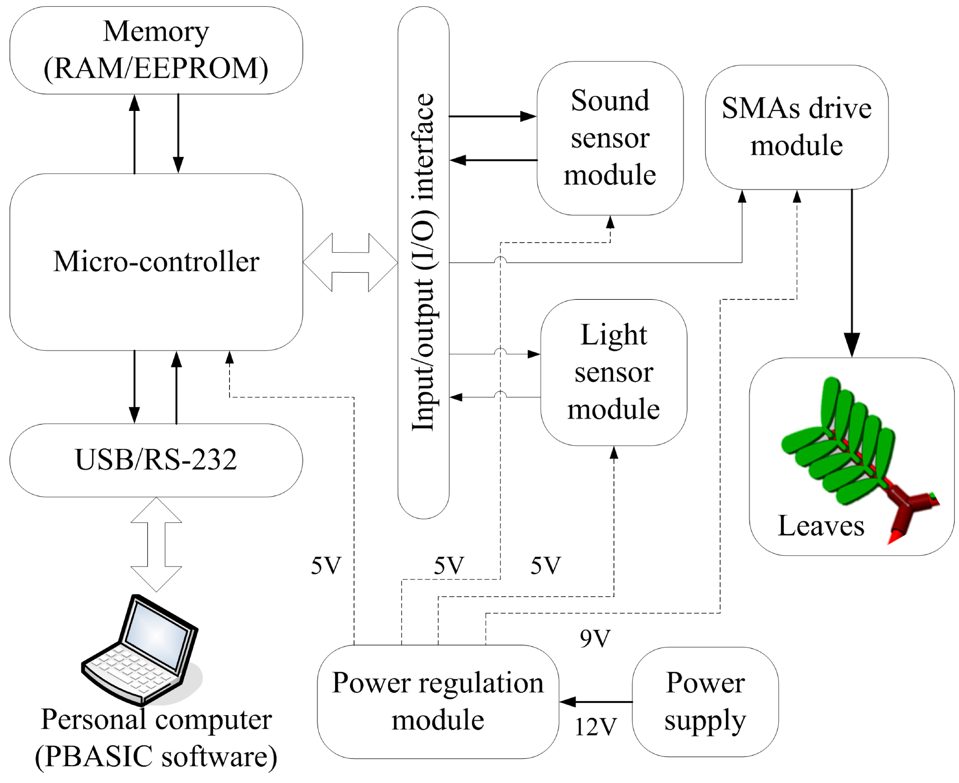
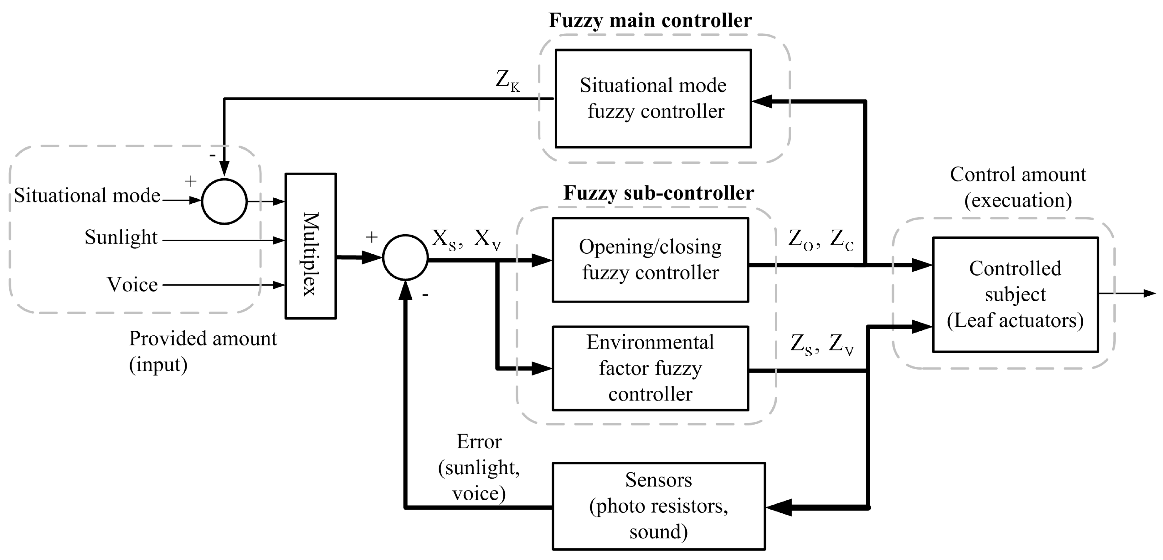
2.1. System Description

The system appearance is shown in Figure 2a. The left top of Figure 2a shows multiple switching groups for users to manually direct leaf swinging, opening, and closing behaviors. Figure 2b illustrates the internal circuit system configuration.
The architecture of the proposed system is as shown in Figure 3, which uses a micro-controller to realize system control. The controller’s instructions are encoded by the interpreter prior to being connected to the micro-controller via the transmission interface (USB or RS-232). After the action planning, the micro-controller obtains the values of the environmental factors of Voice and Sunlight through the input and output interface. Finally, the decision-making values are transmitted to the embedded control system for control of the bionic mimosa robot. The micro-controller system is powered by an external 12 V power supply, and the SMA drive module uses a 12 V power supply for the operational experiment.
Figure 2. Mimosa system appearance: (a) mimosa robot shape and (b) internal circuit board configuration.
Micromachines 06 00042 g002
Figure 3. Bionic mimosa robot system architecture.
Micromachines 06 00042 g003

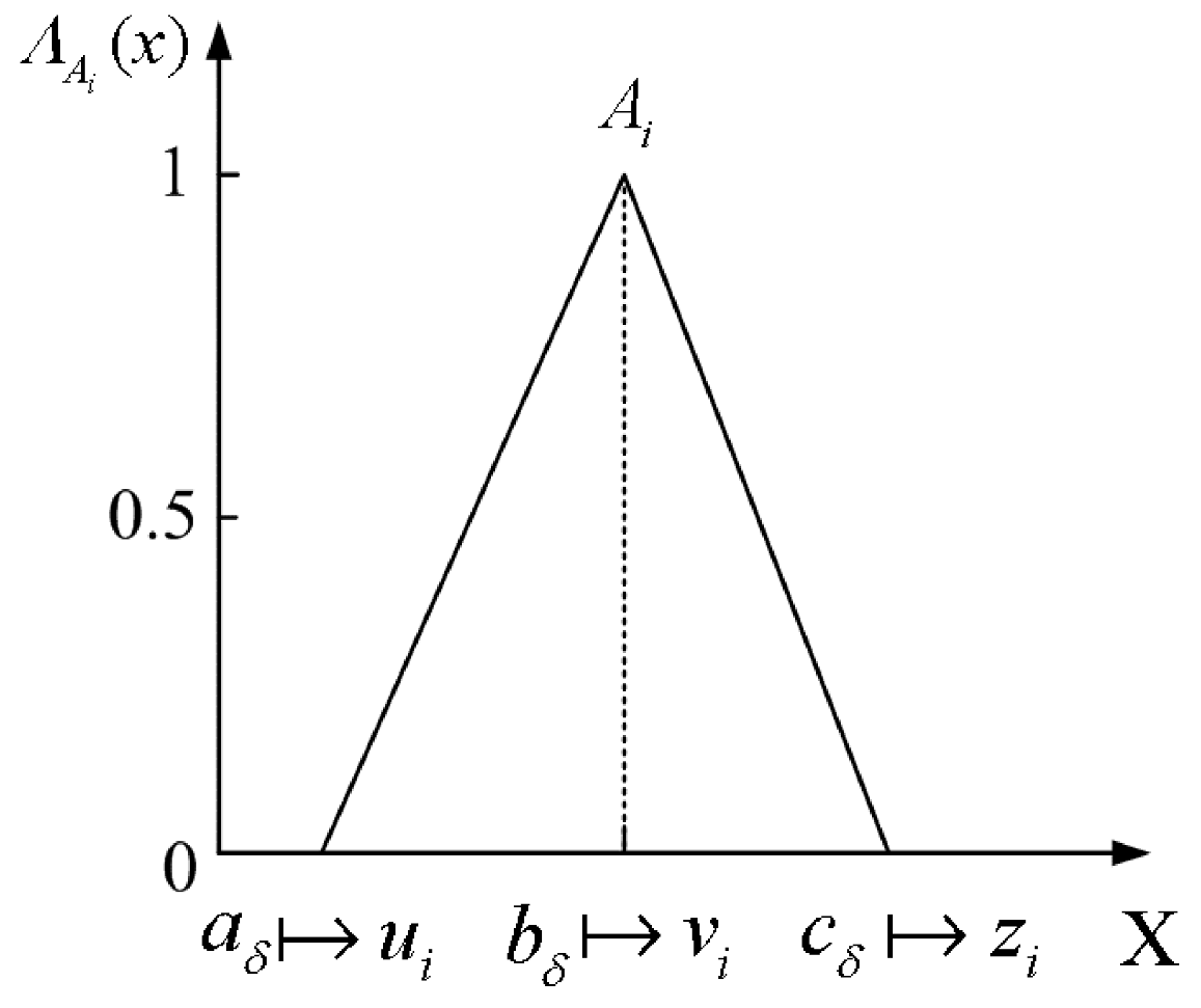
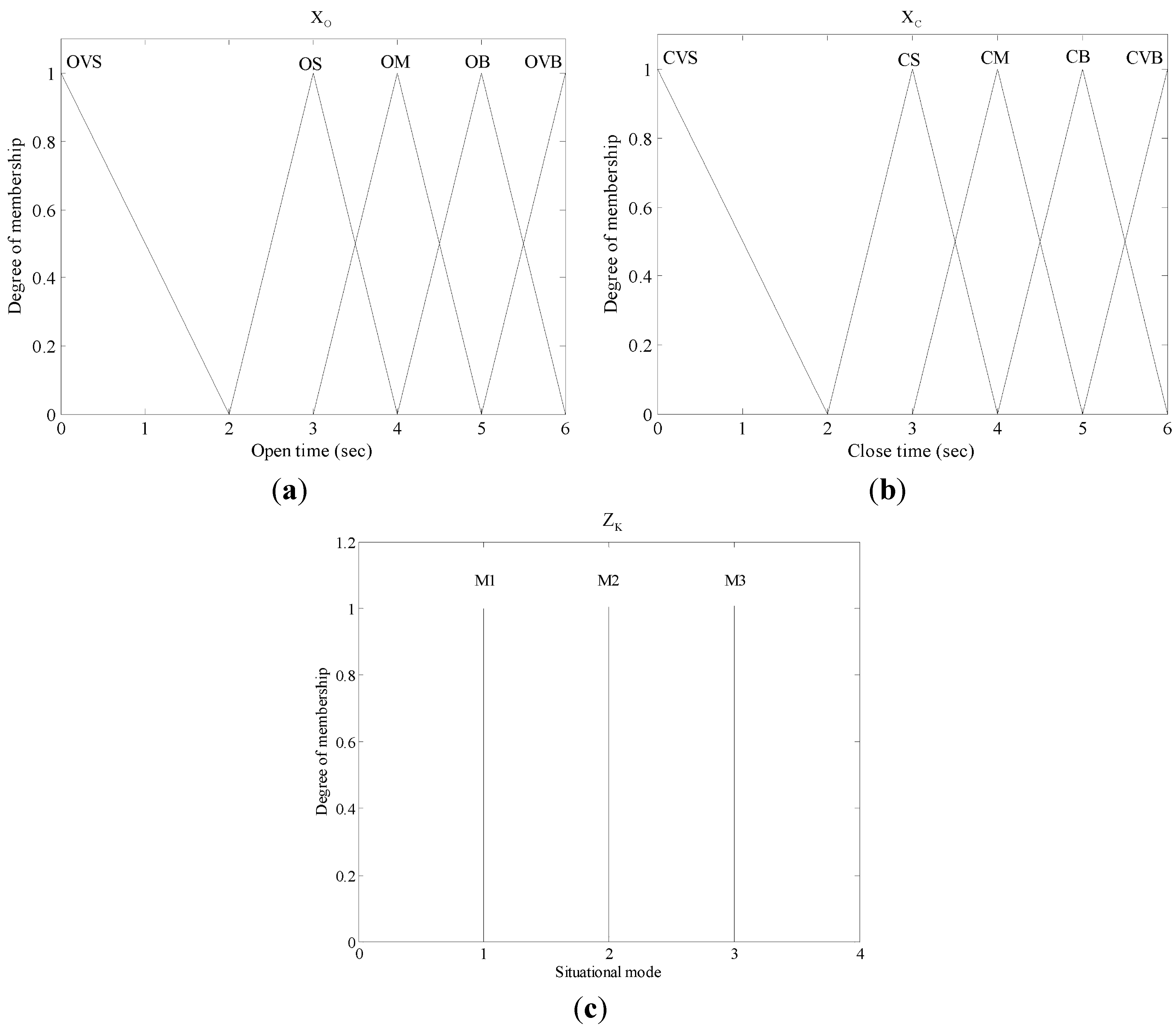
2.2. Fuzzy Control System

As mimosa opening/closing behaviors are significantly affected by Sunlight and Voice, when light and voice intensities are strong, the opening/closing responses are rapid. The opening/closing of all leaves of the strain are not simultaneously completed in sequence, as it is relatively difficult to establish the mimosa opening/closing model. Therefore, this study applied a fuzzy logic inference system for decision-making regarding mimosa opening/closing behaviors. Three situational modes were developed according to the mimosa behavioral demonstration. Each situational mode had its corresponding fuzzy logic inference, which can be further integrated into a multi-layered fuzzy controller. The framework of the proposed control system is shown in Figure 4.
Figure 4. Architecture of the multi-layered fuzzy control system.
Micromachines 06 00042 g004
The input end of the multi-layered fuzzy controller system receives the values of light sensing and voice, which are transmitted to the environmental factor fuzzy controller and leaf opening/closing controller. The output of the opening/closing controller controls leaf opening/closing time. The output of the environmental factor fuzzy controller controls the leaf behavioral display and swing. Finally, the environmental sensors sense the current environmental factors, and feed the values back to the input end for the next system actuation. During implementation of the system, the output signals of the opening/closing fuzzy controller and environmental factor fuzzy controller can be in the situational mode for the situational mode fuzzy controller. The design steps of the proposed fuzzy control are illustrated as follows [17,18]:
Step 1: Define input and output variables and various language labels databases:
First, this study defined five basic linguistic statements: Very Small (VS), Small (S), Medium (M), Big (B), Very Big (VB), and then defined each controller’s input and output variables.
A. Input variables:
(1) Fuzzy sub-controller for environmental factors and opening/closing:
The number of input variables for environmental factors and growth rate are the same.
(1) SUNLIGHT (XS), where the corresponding linguistic statements are SUNLIGHT VERY SMALL (SVS), SUNLIGHT SMALL (SS), SUNLIGHT MEDIUM (SM), SUNLIGHT BIG (SB), SUNLIGHT VERY BIG (SVB); (2) VOICE (XV), where the corresponding linguistic statements are VOICE VERY SMALL (VVS), VOICE SMALL (VS), VOICE MEDIUM (VM), VOICE BIG (VB), VOICE VERY BIG (VVB).
(2) Fuzzy main controller:
The input port of the growth stage main controller can be regarded as the output ports of the opening/closing fuzzy controller, meaning the output variables of the opening/closing fuzzy controller become the input variables of the fuzzy main controller. In OPEN TIME (XO), the input variables include five fuzzy sets, each of which include: OPEN TIME VERY SMALL (OVS), OPEN TIME SMALL (OS), OPEN TIME MEDIUM (OM), OPEN TIME BIG (OB), OPEN TIME VERY BIG (OVB); in CLOSING TIME (XC), there are also five fuzzy sets, each of which include: CLOSE TIME VERY SMALL (CVS), CLOSE TIME SMALL (CS), CLOSE TIME MEDIUM (CM), CLOSE TIME BIG (CB), CLOSE TIME VERY BIG (CVB).
B. Output variables:
(1) Opening/closing Fuzzy controller:
The output variables for the opening/closing fuzzy controller include opening time (ZO) and closing time (ZC). In opening time (ZO), the five fuzzy sets are OVS, OS, OM, OB, and OVB; in closing time (ZC), the five fuzzy sets are CVS, CS, CM, CB, and CVB.
(2) Fuzzy main-controller:
The fuzzy main controller acts as the decision-making system, which determines whether the next mode can be reached from the output of the opening/closing fuzzy sub-controller. The main controller has only one situational mode output variable (ZK), and five output fuzzy sets: Mode 1 (M1), Mode 2 (M2), and Mode 3 (M3).
(3) Environmental factor fuzzy controller:
The output variables of the environmental fuzzy controller are sunlight (ZS) and voice (ZV), and their main purpose is to provide compensation for environmental factors. When too much input is provided, supply is reduced, and when input supply falls short, more is provided. Each of the output variables has five fuzzy sets, and the design is the same as that of the input variables.
The input variables, output variables, and fuzzy linguistic labels in the fuzzy sub-controller are organized in Table 1 and Table 2, respectively.
Table 1. Input values and linguistic labels.
XSXV
(aS, bS, cS)Linguistic Labels(aV, bV, cV)Linguistic Labels
(0, 30, 60)SVS, SS, SM(0,0.5,1)VVS, VS, VM
(30, 60, 90)SS, SM, SB(0.5,1,1.5)VS, VM, VB
(60, 90, 120)SM, SB, SVB(1,1.5, 2)VM, VB, VVB
Table 2. Output values and linguistic labels.
ZSZVZOZC
(aS, bS, cS)Linguistic Labels(aV, bV, cV)Linguistic Labels(aO, bO, cO)Linguistic Labels(aC, bC, cC)Linguistic Labels
(0, 30, 60)SVS, SS, SM(0, 0.5, 1)VVS, VS, VM(2, 3, 4)OVS, OS, OM(2, 3, 4)CVS, CS, CM
(30, 60, 90)SS, SM, SB(0.5, 1, 1.5)VS, VM, VB(3, 4, 5)OS, OM, OB(3, 4, 5)CS, CM, CB
(60, 90, 120)SM, SB, SVB(1, 1.5, 2)VM, VB, VVB(4, 5, 6)OM, OB, OVB(4, 5, 6)CM, CB, CVB
In Table 1 and Table 2, aδ, bδ, and cδ illustrate the physical values corresponding to the three vertexes of the triangular membership function, and δ denotes any of the various input/output variables. The design of the fuzzy membership function is described in the next section.
Step 2: determine fuzzification strategy
After defining the input and output variables, the variable values are fuzzified according to the fuzzy set theory. First, the true value range of the input and output values are converted into the fuzzy domain, where membership functions are selected for value fuzzification. Next, the membership degrees of the membership functions are obtained.
Regarding the selection types of membership functions, single tone, trapezoidal, and bell-shaped types are utilized. The triangular type is used as the membership function for the fuzzy sub-controller. The function of Λ A i ( x ) is shown as follows:
Λ A i ( x )= { 0,           x  <  u i x u i v i u i ,         u i x v i z i x z i v i ,         v i x z i 0,          x  >  z i
where Ai is the ith fuzzy set, and the values of ui, vi, and zi depend on the linguistic labels. Fuzzification is carried out, which is a crucial procedure where input data are converted into the fuzzy domain using the membership function. When a specific value is entered, it is calculated by the predesigned membership function, which uses an intersection operation to derive the degree of membership, and results in fuzzification. The defined items in the membership function are shown in Figure 5. Figure 6 illustrates the distributions of the input and output membership functions in the fuzzy main controller. It is noteworthy that the single tone type membership function is utilized in the fuzzy main controller.
Figure 5. Membership function of fuzzification.
Micromachines 06 00042 g005
Figure 6. Input and output membership functions of fuzzy main controller: (a) membership function of open time fuzzification; (b) membership function of close time fuzzification; (c) membership function of situational mode controller output.
Micromachines 06 00042 g006
Step 3: design of fuzzy rule table
The inference rule sentence can be displayed by “IF … AND … THEN …” and the example is described, as follows:
If “Sunlight” is “SVS” and “Voice” is “VVS”, then “Open Time” is “OVS”.
The system has three fuzzy controllers, and the rule base of the situational model controller is as shown in Table 3. The rules are relatively simple, and the situational mode can be judged by the opening/closing signals. The two remaining controls are the opening/closing fuzzy controller and the environmental factor fuzzy controller. The control rule base is as shown in Table 4 and Table 5. The rules are defined by judging the changes in the variables of Sunlight and Voice.
Step 4: design fuzzy deduction method
This is the fuzzy inference and analysis decision-making core. In this study, the fuzzy inference method of the AND condition of the same inference rule can be computed using the Min-Dot method [17,18].
Step 5: select method of defuzzification
After inference by fuzzy logic, the output is a fuzzy set. The simplest approach is the bisector method, which first obtains the area of the region enclosed by the membership function curve of the fuzzy sets and vertical coordinates, and then identifies the vertical line that bisects the region into two portions of equal areas [17,18].
Table 3. Situational mode fuzzy rule table.
ZMXo
OVSOSOMOBOVB
XcCVSM1M1M1M1M2
CSM1M1M2M2M2
CMM2M2M2M2M3
CBM2M2M2M3M3
CVBM3M3M3M3M3
Table 4. Open/Close time fuzzy rule table.
ZO, ZCXS
SVSSSSMSBSVB
XVVVSOVS, CVBOVS, CVBOS, CBOM, CBOM, CB
VSOVS, CBOS, CBOS, CMOM, CMOM, CM
VMOS, CBOM, CMOM, CMOM, CMOB, CS
VBOM, CMOM, CMOM, CSOB, CSOB, CVS
VVBOB, CMOB, CMOB, CSOVB, CVSOVB, CVS
Table 5. Rule table of environmental factor fuzzy controller.
ZS, ZVXs
SVSSSSMSBSVB
XvVVSSM, VB SB, VMSVB, VVBSVB, VMSVB, VS
VSSVS, VS SS, VMSB, VB SVB, VVB SVB, VVB
VMSVB, VM SB, VMSM, VMSS, VMSVS, VM
VBSVS, VVSSVS, VS SS, VSSM, VM SB, VB
VVBSVS, VBSVS, VMSVS, VVSSS, VM SM, VS

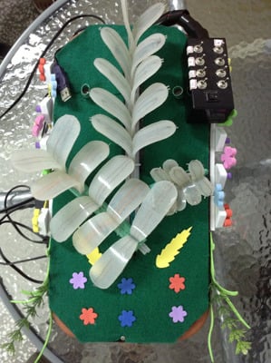
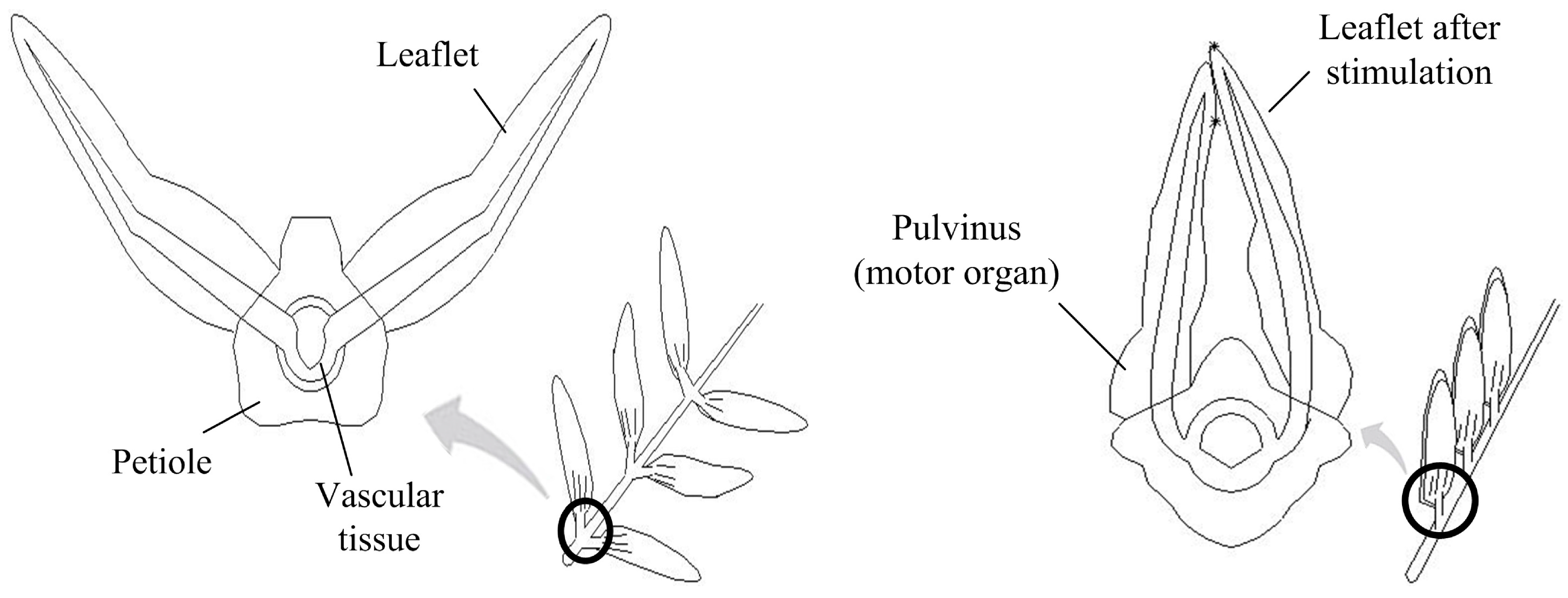
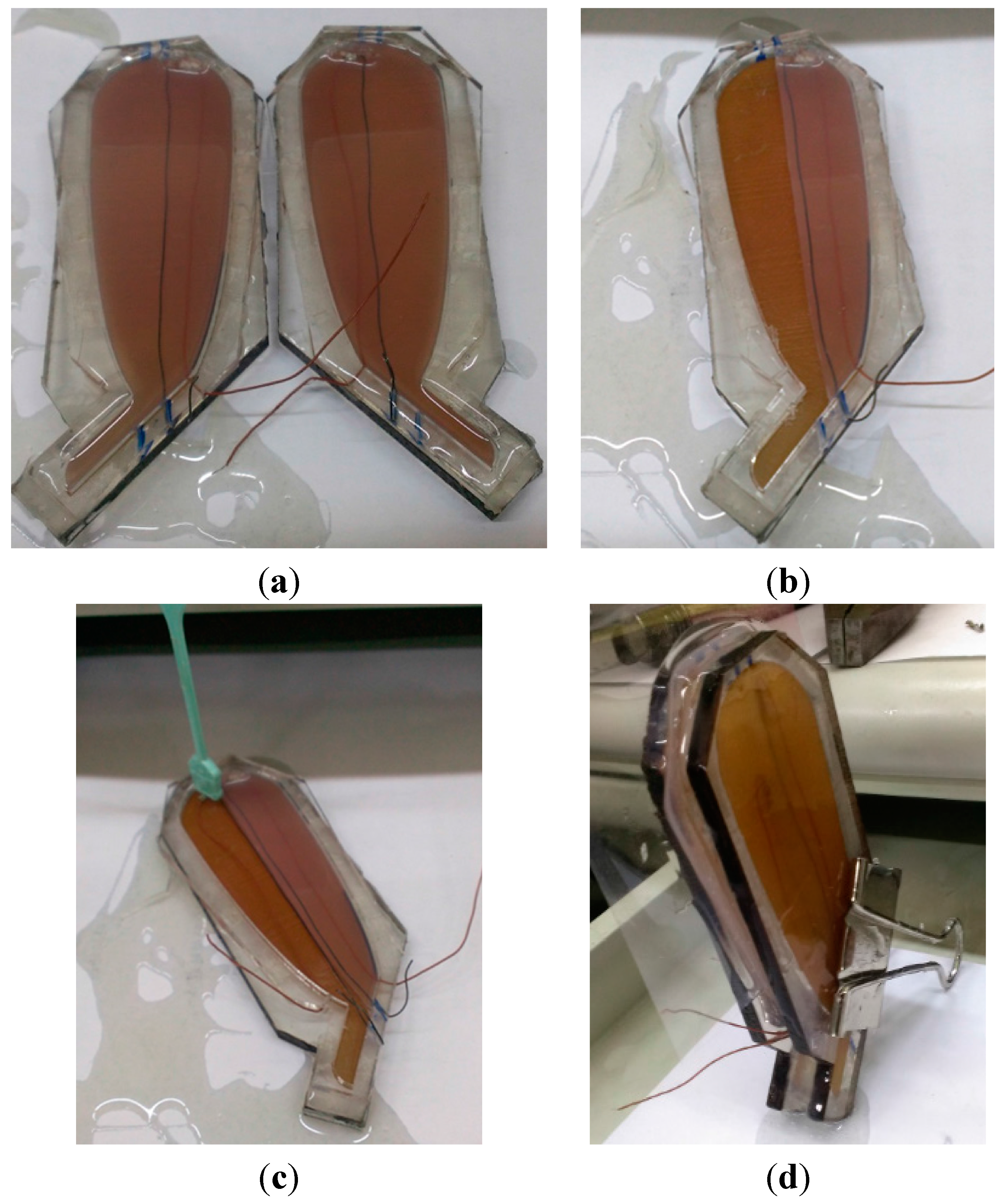
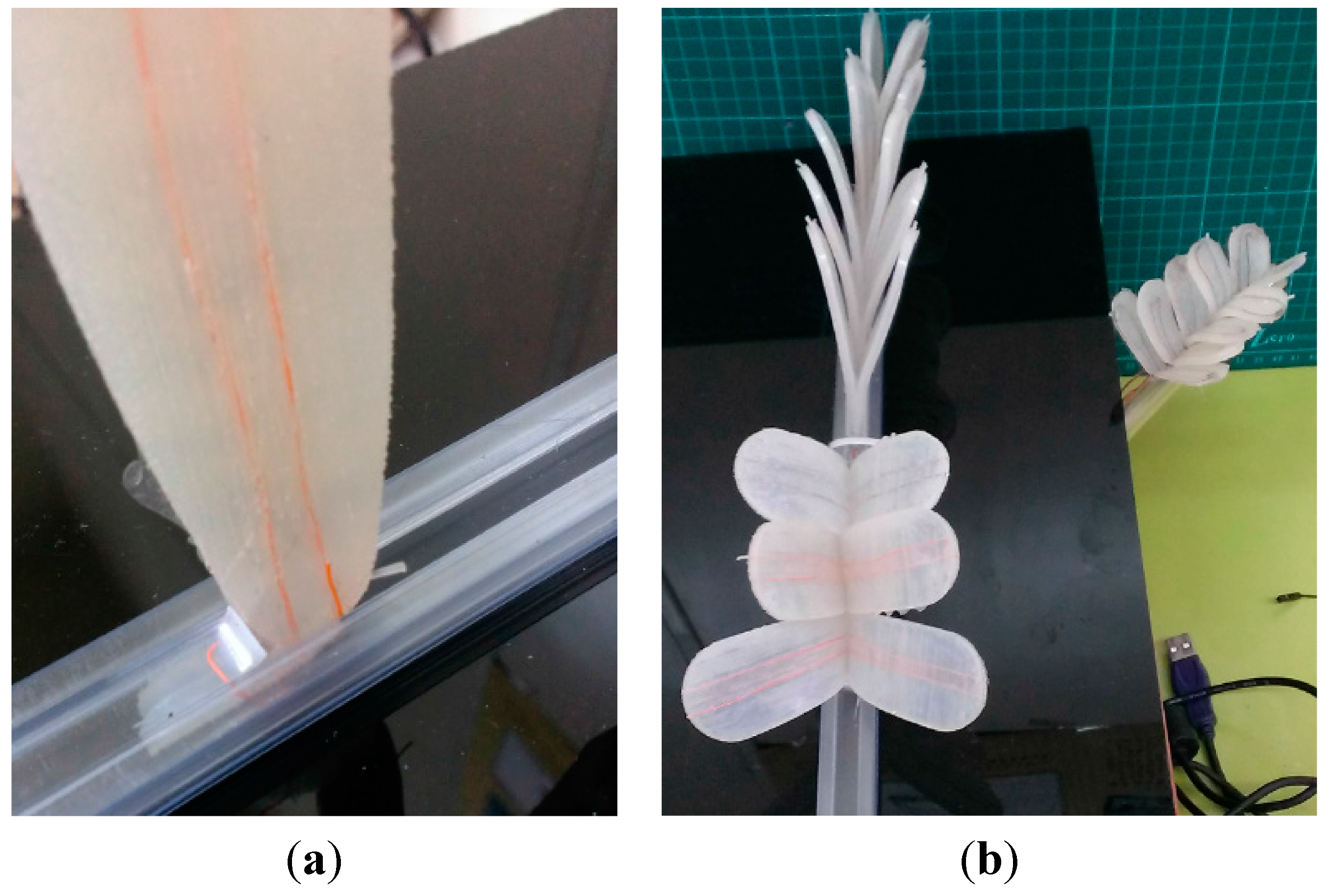
2.3. Leaf and Vein Design

The mimosa leaf production process and vein-leaf integration design are illustrated as follows.

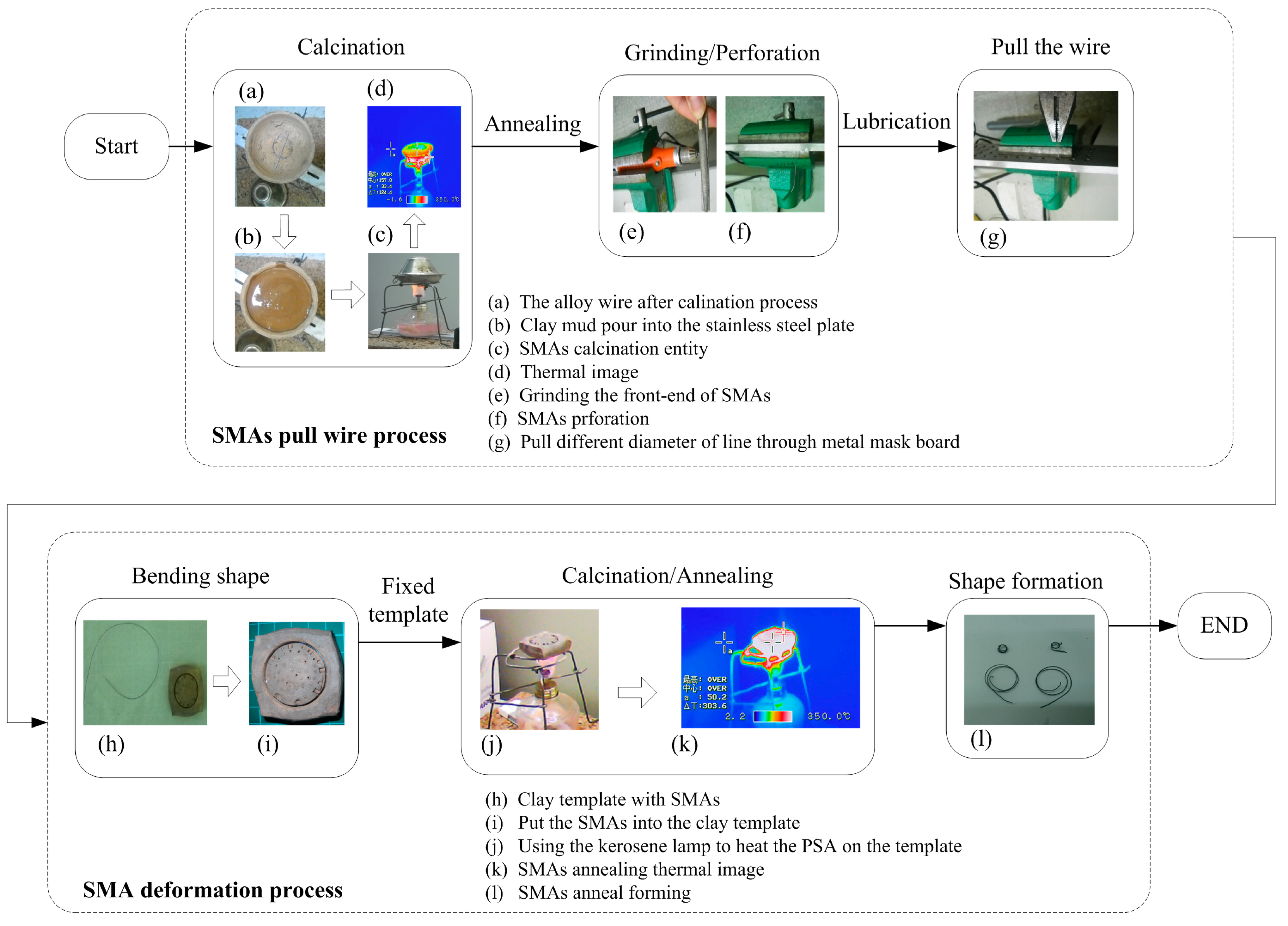
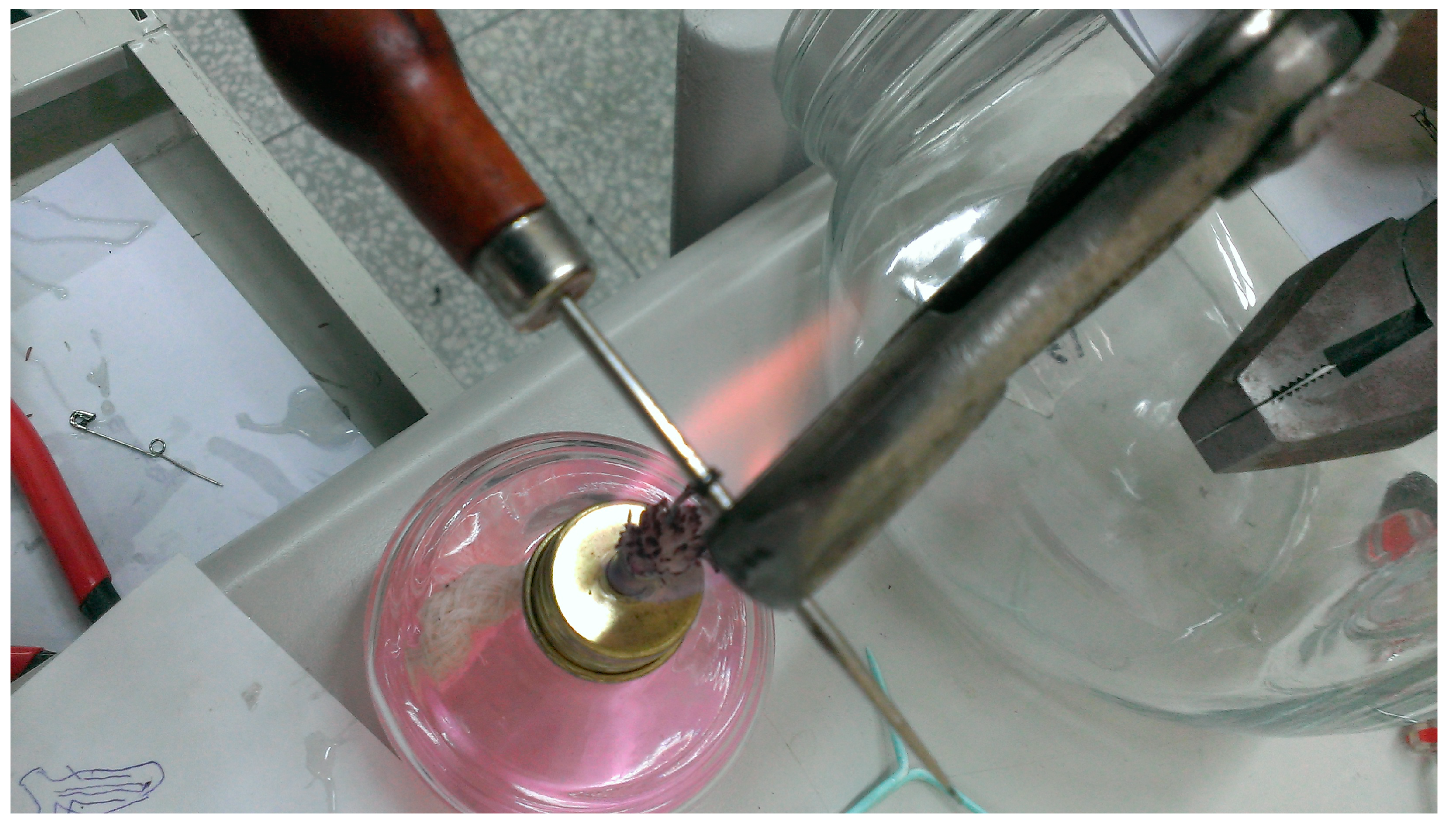
2.3.1. SMAs Processing and Memory

SMA is an alloy that can memorize a shape after thermal processing. When the temperature of the SMA is lower than the deformation temperature, after the plastic deformation of the Martensite Phase, it can restore the pre-deformation shape when the temperature is restored to the range of the Austentile Phase by heating. Such a phenomenon is known as the memory effect [19]. The recovery effect of SMA is related to the sectional area and length, then obtains additional SMAs of different size dimensions requires mask pull plates prior to starting the shape memory. Figure 7 illustrates the SMA processing and memory processes.
A. SMAs pull wire process
First, the wire was annealed to ensure better flexibility, which also increases the wire pull success rate. The wire stiffened slowly after being pulled several times, and it was repetitively annealed and pulled. The annealing flame should not be too hot in order to prevent the wire from melting due to incaution. The fire was quenched when the metal surface turns to white from red, and then the wire was left to cool naturally to room temperature. The wire was calcined by a spirit lamp after it was placed in a stainless steel disc, covered with clay. A stainless steel lid was placed over the disc. In addition, an infra-red thermograph was used to sense the annealing temperature. The wire continued to be calcined for 10 min at over 350 °C, then the lamp was quenched, in order to allow the wire to cool naturally (see Figure 4a).
Second, the punching and grinding operations were conducted. As the front end of the annealed memory wire was threaded through the wire hole, its 2–3 cm long portion was ground fine. The wire was gripped by the gripping head of the carving drill. The drill started to drive the gripping head, and it was held by the wire to rotate. These two files were used to approach the rotating wire in order to grind it fine.
Third, the lubricating operation was performed. Lubricating oil or butter was smeared onto both the wire pulling hole and the wire. The purpose of this step is mainly to reduce pulling friction, increase the pulling success rate, and reduce the probability of alloy cable rupture.
In the final step of wire pulling, the SMA cable diameter was 0.5 mm, and the ideal cable diameter was 0.3 mm for implantation inside a PDMS leaf. The alloy cable was pulled from the larger holes to the smaller holes in order to gradually obtain a thinner alloy cable [20].
B. SMA deformation process
A high temperature heating furnace is commonly used for anneal forming of SMA. The crystal lattices of SMA are rearranged and recombined in the presence of the high temperature of the furnace in order that the SMA can memorize the shape formed at annealing. However, a high temperature heating furnace is very expensive, thus, in this operation, a spirit lamp and clay were used to create the shape forming template of SMA. During calcination, the SMA wire was secured in the clay template, where it underwent even heating and annealing formation (see Figure 7). As the clay template should be made red-hot to provide even heating, the process requires a long time.
This study replaced the clay template heating method with direct heating of the alloy, as this method can shorten heating time. First, SMA was wound on high temperature-resistant objects according to the desired bending degree or method, such as a circular iron bar or copper column. The bending shape was then fixed before placing the object directly above an alcohol lamp for 5–10 min of heating. Since the temperature of alcohol lamp heating was 400–500 °C, it could change the SMA phase to realize the function of memory (see Figure 8).
Figure 7. SMA processing and memory process.
Micromachines 06 00042 g007
Figure 8. Direct heating of the SMAs.
Micromachines 06 00042 g008

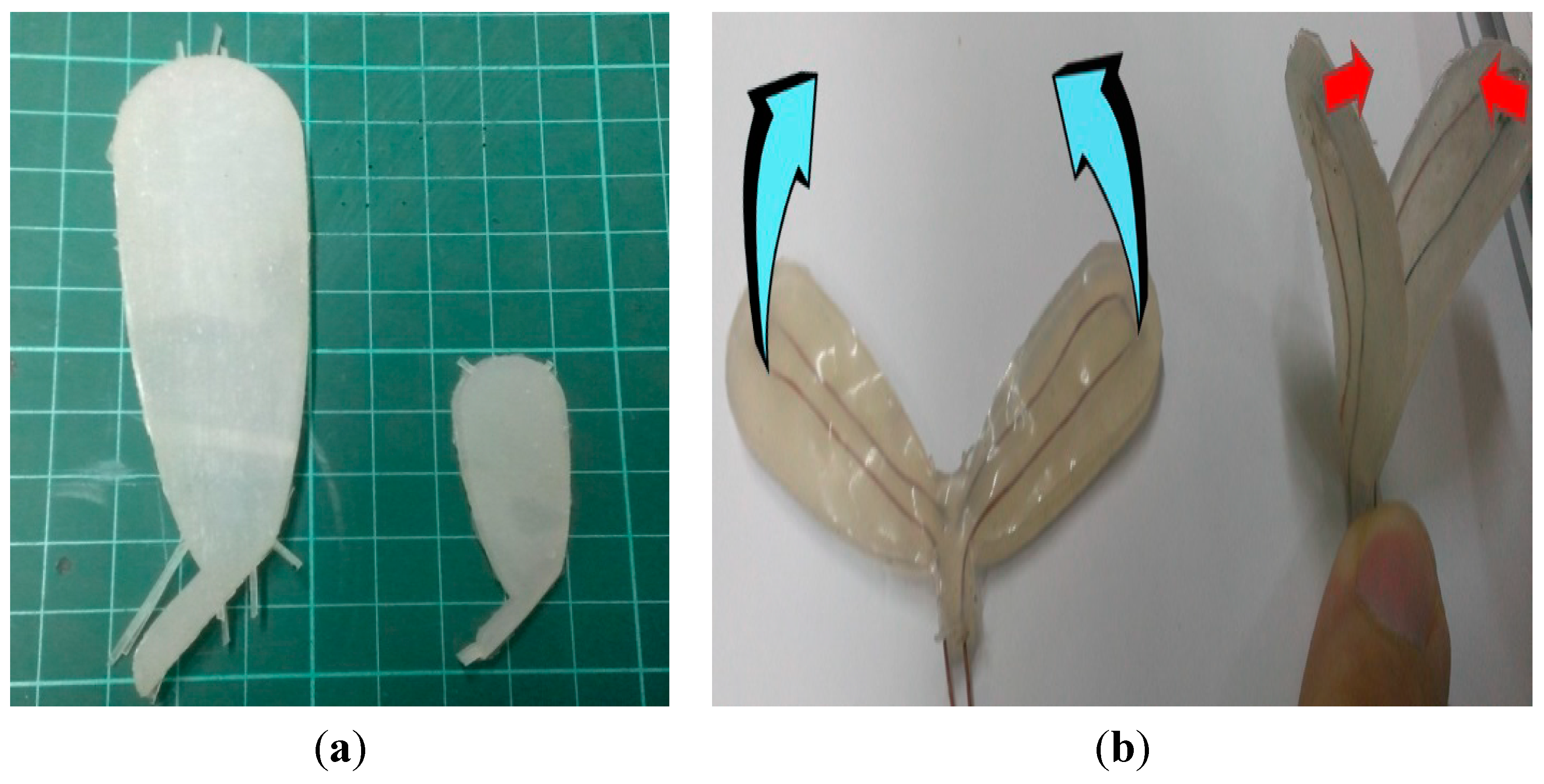
2.3.2. Leaf and Vein Design and Implementation

This study chose Polydimethylsiloxane (PDMS) as the leaf material [21,22], as cured PDMS can become an elastomer with excellent toughness, high insulation, and water repellency. The major veins are realized by SMAs and wire. The connection points are not realized by soldering, but by the DuPont crimping method, which can avoid breaking the connection point due to solder falling while in the high temperature state, thus, causing bending of unheated SMAs. Next, the crimped wires and SMAs are input into the template. At this step, the memory side of SMAs should be particularly noted, and this study addressed fixing the memory side of the template according to the designed directions of bending SMAs. Afterwards, the prepared PDMS was poured into the template containing the wire and SMAs. In preparation of PDMS, the ratio of PDMS and hardener should be particularly noted. In this study, the ratio was 2.5% (temperature 28 °C), the operation time was 25 min, and the hardening time was 5 h. In the process of preparation and mixing, bubbles were produced inside the PDMS material, which required a vacuum machine for removal in order to avoid structural properties changes caused by any remaining bubbles inside the PDMS during hardening and shaping. Finally, the prepared PDMS was poured into the template to 80% of the volume (see Figure 9a), and placed at room temperature, or in an oven to accelerate curing.
Figure 9. Leaf production processes: (a) PDMS infusion mode of 80% volume being filled for hardening; (b) remove other side of PDMS at the center; (c) implant SMA in the position of removal; (d) symmetric binding after the second infusion.
Micromachines 06 00042 g009
The leaf should contain two SMAs of opposite memory sides in order to display the opening and closing directions. However, when making the leaf, if two SMAs were placed in the template before pouring the PDMS, it would be difficult to ensure that the positions of the SMAs are according to the desired directions. Therefore, this study placed an SMA at the center of the vein, and developed a leaf up to 80% of the capacity. After curing and hardening the PDMS, half of the PDMS leaf without the SMA was removed from the center of the template vein (see Figure 9b). Next, another SMA was placed (Figure 9c) to recreate the second half. The finished product was a leaf with dual SMAs of up to 80% in volume. At the early stage, the designed leaf was of single plane production, meaning that the implantation of SMA was placed in the single plane PDMS mode in order to realize the opening/closing of the leaf. However, the opening and closing behaviors were not ideal subjects for plane limitations. Under such a condition, this study applied a different method of creating a mode to fill the void space remaining in the above-mentioned leaf of 80% volume of PDMS, which is the second infusion. Next, the two leaves were bound. Prior to binding, transparent film or slides were used to separate the bonding and non-bonding parts of the leaves at the appropriate positions for molding (see Figure 9d). Figure 10a illustrates completed leaves.
Figure 10. Appearance of completed mimosa leaves: (a) completed leaves; (b) 2-dimension leaf (left), and 3-dimension leaf (right).
Micromachines 06 00042 g010
The leaf production of this study differed from the previous methods of leaf production. In the past, leaf production achieved the two-dimensional state by implanting the SMA in a single-sided PDMS mold in order to realize the opening/closing behaviors of the leaf. However, these behaviors were not desirable due to the limitations of the plane. In such a situation, this study applied another method of creating a mode to fill the void space remaining in the above-mentioned leaf of 80% volume by PDMS, which is the second infusion. Next, the two leaves were bound. Prior to binding, transparent film or slides were used to separate the bonding and non-bonding parts of the leaves at the appropriate positions for molding. Figure 10b illustrates the differences of a two-dimensional leaf and a three-dimensional leaf during opening/closing. As seen, the bending degree of SMAs was greater in the case of the two-dimensional model, thus, the opening/closing actions would be more difficult.
The mimosa branch has numerous pairs of leaves, and the stem should have certain support to facilitate the implantation of a mimosa leaf. Therefore, this study used a plastic cylindrical case to wrap the pairs of leaves. Figure 11 illustrates the prototype of the entire strain of the mimosa.
Figure 11. Appearance of strain prototype: (a) a single leaf implanted in a plastic cylindrical case; (b) numerous pairs of leaves implanted in the prototype.
Micromachines 06 00042 g011

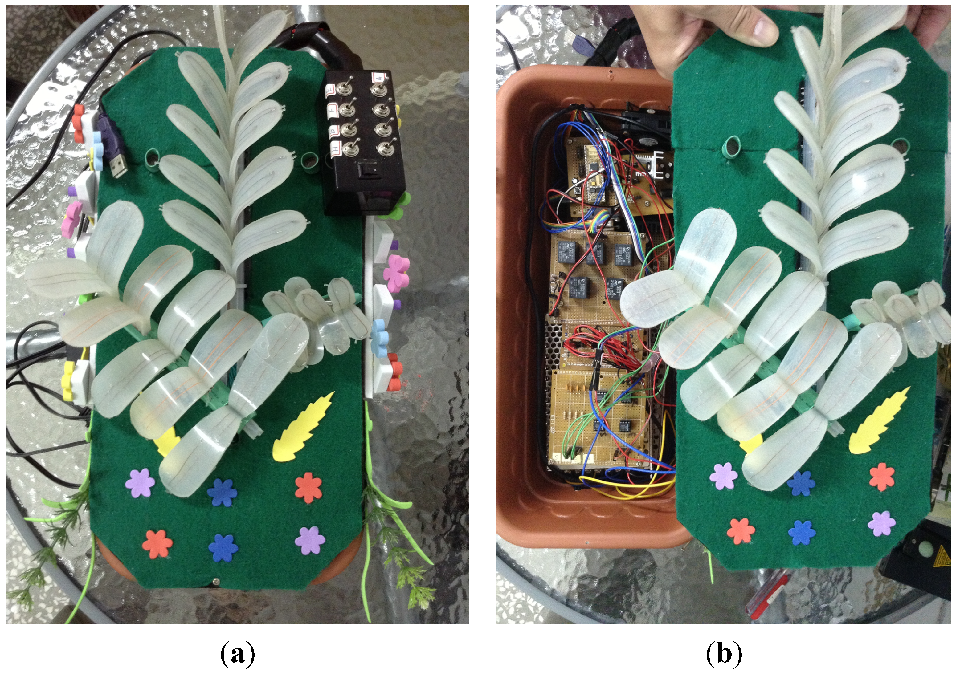
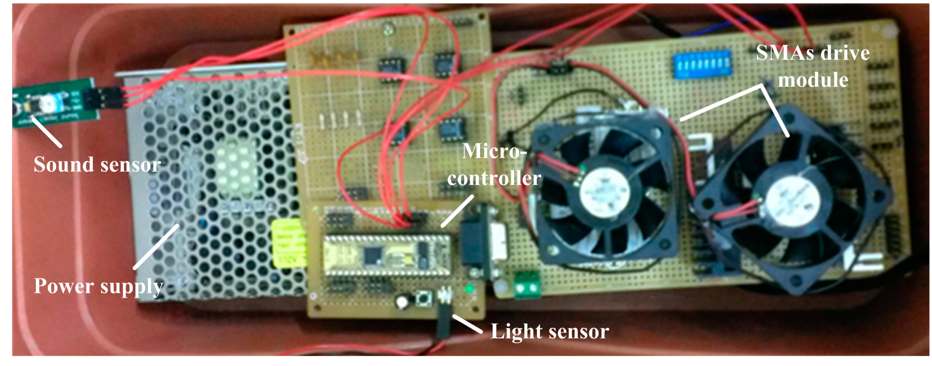
2.4. Control System Implementation

This section introduces the hardware circuit design, peripheral modules, and software program processes.

2.4.1. Hardware Circuit Design

The bionic mimosa robot hardware devices included a major control module and a sensing and driving module (see Figure 12). The sensing and actuation module consisted of a power stabilization module, Sunlight sensing module, Voice sensing module, and SMA actuation module. The circuit design and functions of the modules are illustrated as follows.
Figure 12. Embedded control board.
Micromachines 06 00042 g012
A. Major control module
In this study, the control core of the system is a micro-controlling development board. The controller is produced according to Parallax Inc. (Rocklin, CA, USA) [23], and consists of various components, including a micro-controller, electrically-erasable programmable read-only memory (EEPROM) memory chip, serial transmission interface, and power stabilization chip. The system has a built-in BASIC programming language interpreter known as PBASIC, which can provide users with functions for development.
B. USB communication module
The main function of the module is to enable two-way serial communication between the BS240p development board and a PC without a serial communication card.
C. Sunlight sensing module
The Sunlight sensing module consists of a photosensitive resistor, 555 chip vibrator, and a capacity device, which can receive the output values sent by the sensing module through the PULSIN pin of the BS240p development board.
D. Voice sensing module
The Voice sensing module is one of the environmental factors of the proposed system, and is a product of Parallax. The advantage of the sensor is easy operation, which enables it to connect with the BS240p development board.
E. SMA actuation module
The SMA actuation module mainly uses a solid state relay (SSR), a switch, and direct current (DC) power supply to drive the SMAs.
F. Power module
The output voltage of the power supply module can be divided into 5 V, 9 V, and 12 V. The 5 V power supply is mainly for the sensing modules, including BS2, Sunlight sensing, Voice sensing, and SSR relay. In addition, the BS240p development board can provide a power supply of 5 V and 1 A; therefore, it can provide the working voltage for the above modules and electronic devices. The 9 V power supply is mainly for the thermal conduction of the SMA. The power supply module uses MC7809 integrated circuit (IC) to provide a 9 V and 4 A power supply; while the 12 V power supply is for the SMA cooling fan, LED, and other accessory devices.

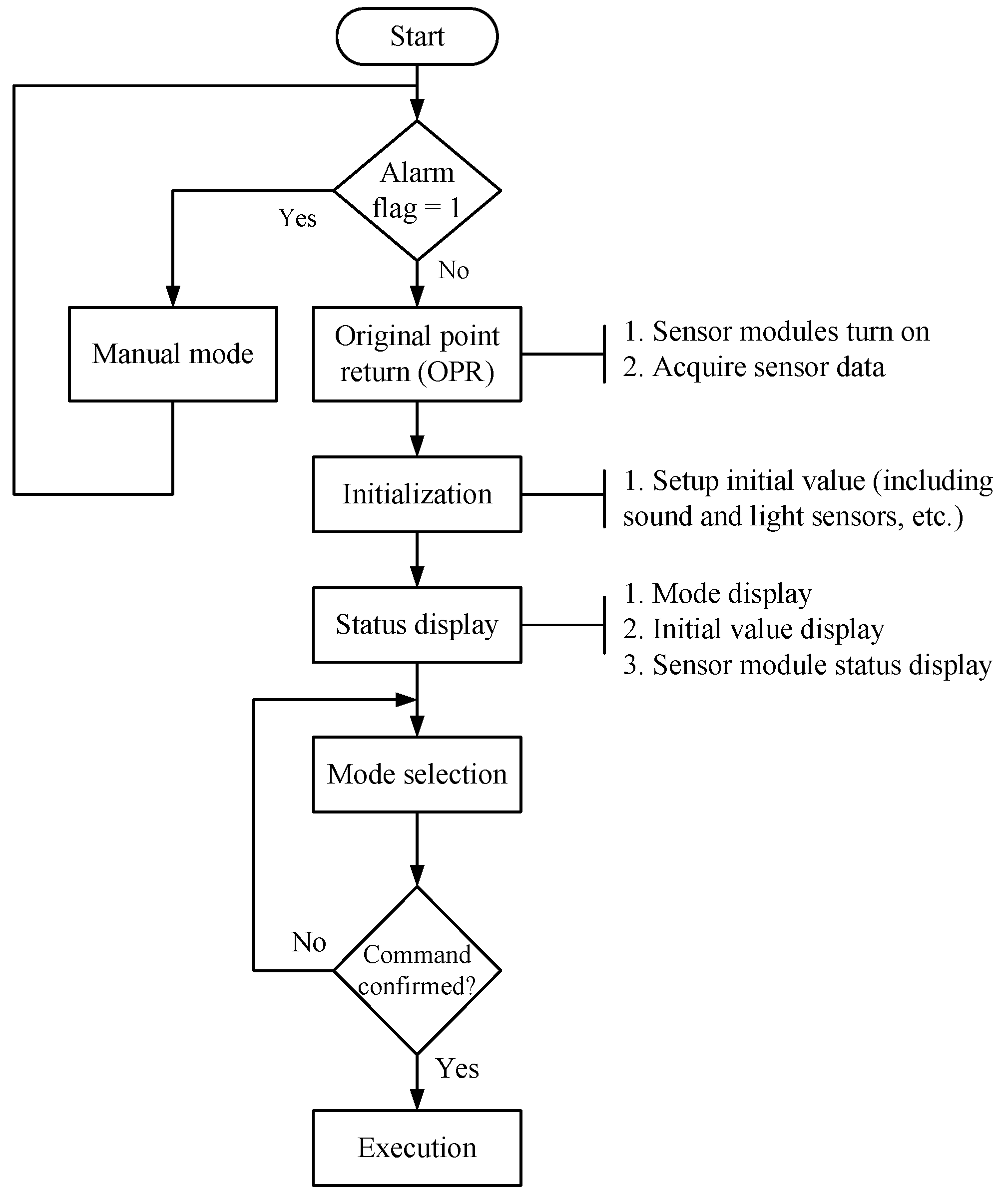
2.4.2. Software Programming Design

The software programming interface is developed by BASIC Stamp Editor v. 2.5, and consists of 70 groups of simple instruction sets and programming interpreters. The tool set is used for writing the Fuzzy Knowledge Base (FKB) for the mimosa opening and control program in order to realize a fuzzy control system. Figure 13 illustrates the main program control flow. After the program resets the system power supply and BASIC Stamp micro-controller, the micro-controller executes system parameter initialization and sets relevant peripheral parameters. The initial parameter initialization settings include the initial Sunlight and Voice values. After initialization is complete, the PC terminal will display a complete message, and enter into the waiting mode for the user to input the relevant control commands, which determine and implement the commands.
Figure 13. Main program control process.
Micromachines 06 00042 g013

3. Results and Discussion

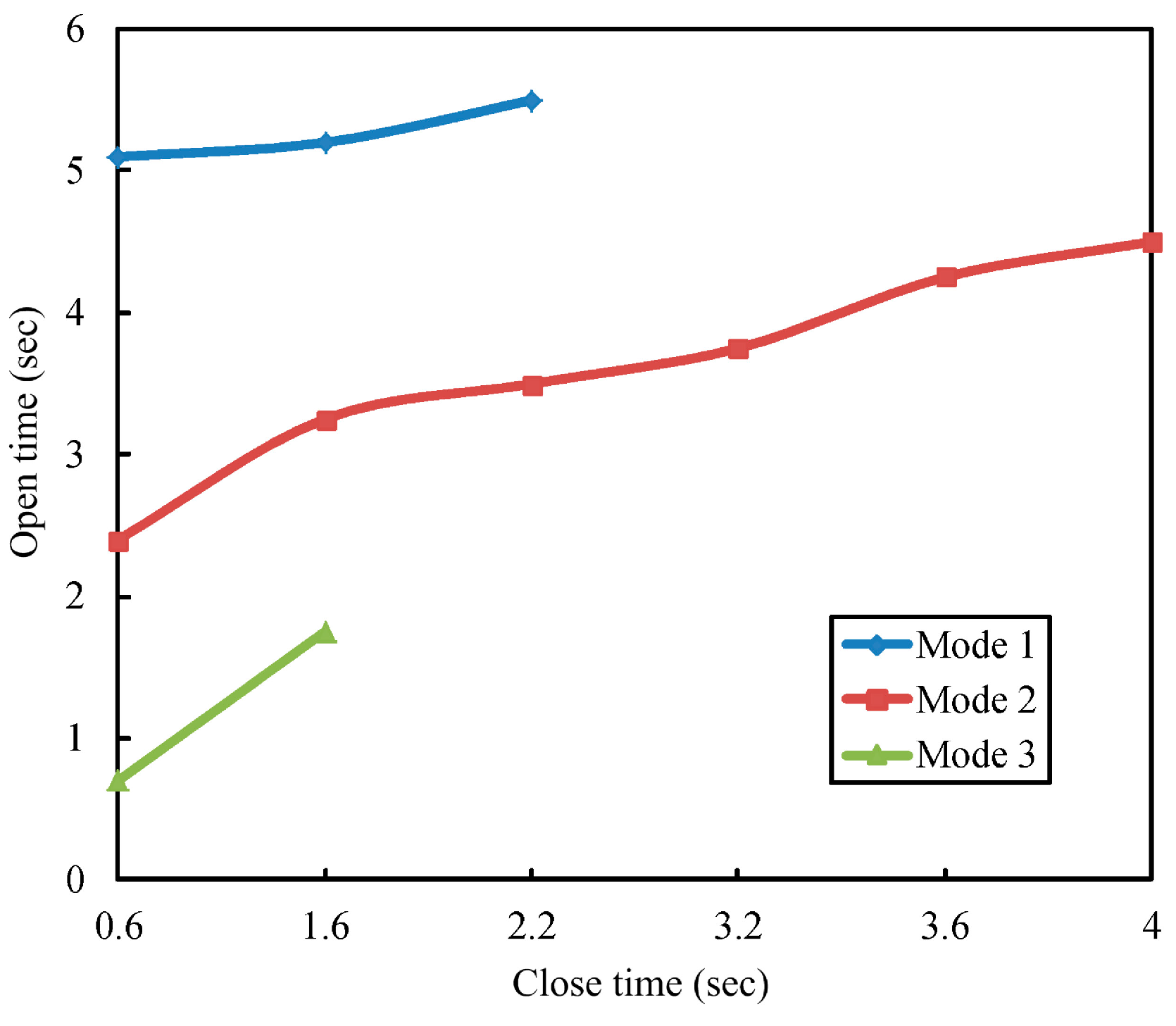
3.1. Behavior Mode Simulation and Verification

To analyze the closing/opening expected values and situational modes for different environmental factors (Sunlight and Voice), this study used MATLAB/Simulink version 2010a for simulation and verification of the fuzzy control system. The simulation results are as shown in Figure 14. As seen, opening/closing times are different in the cases of different modes. Mode 1 illustrates leaf opening when the environmental factor stimulation is significant; Mode 2 illustrates the changes and swing of the leaves in the case of environmental factors only; Mode 3 illustrates the unapparent closing and opening of leaves when the external environment stimulation is insignificant.
Figure 14. Opening and closing times and situational mode simulation results.
Micromachines 06 00042 g014

3.2. System Test

This section illustrates single-pair leaf swing, plant strain swing, and bionic mimosa situational behavior swing experimental results, as well as comparative analysis of leaf opening/closing positions.

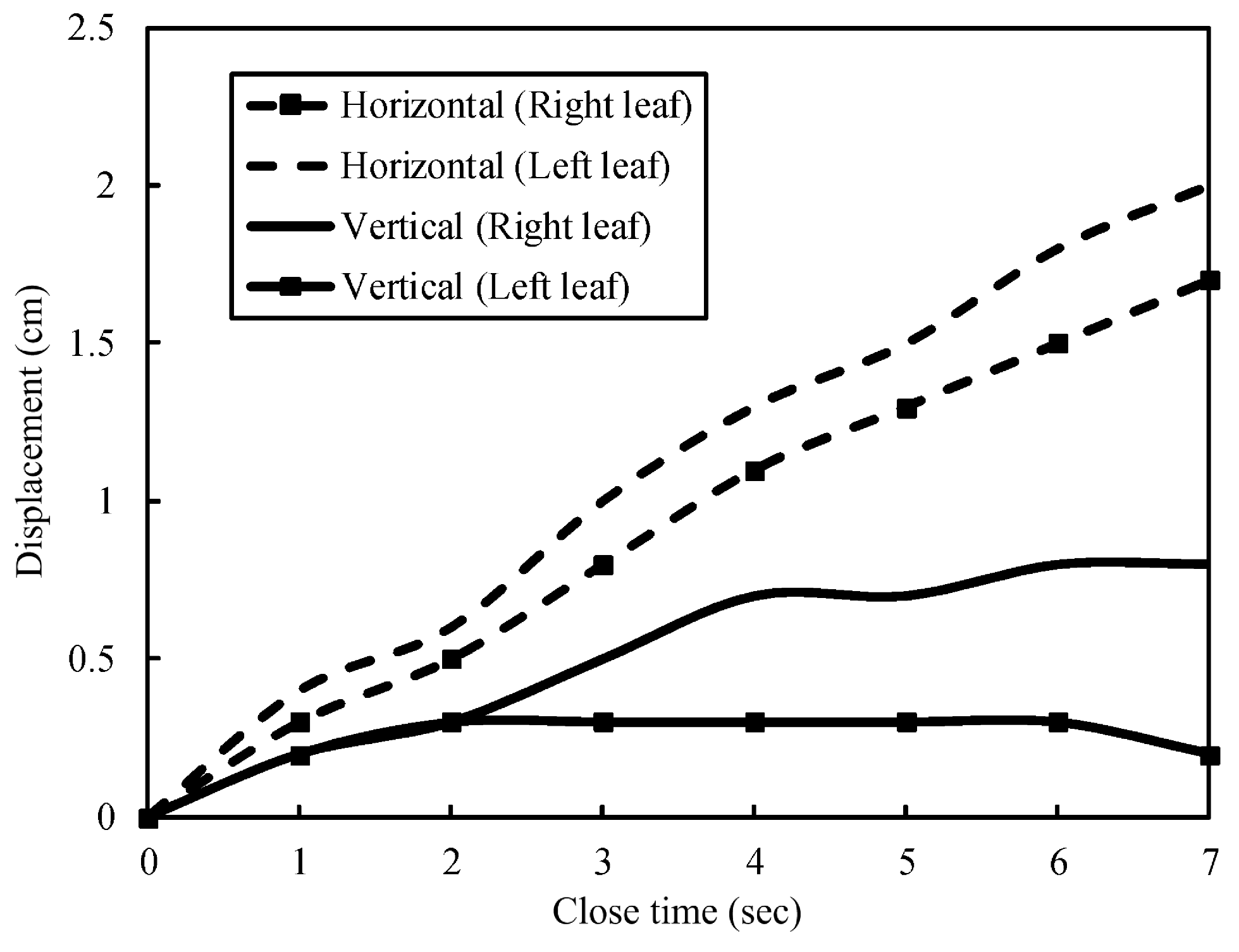
3.2.1. Single-Pair Leaf Swinging

This experiment observed the coordinated displacement of two leaves over time for opening/closing the leaves, where the leaf top is the point of measurement. Figure 15 and Figure 16 illustrate the single-pair leaf opening/closing experiment curves (actuation time and displacement value). As shown in Figure 16, the horizontal displacement of single-pair leaves is relatively consistent; while two leaves have a difference of 0.3 cm displacement. Regarding the closing experiment, as seen in Figure 16, for the same displacement shown in Figure 15, the horizontal and vertical Close Times are shorter than expected.
Figure 15. Single-pair leaf opening experiment curve (open time vs. displacement value).
Micromachines 06 00042 g015
Figure 16. Single-pair leaf closing experiment curve (close time vs. displacement value).
Micromachines 06 00042 g016

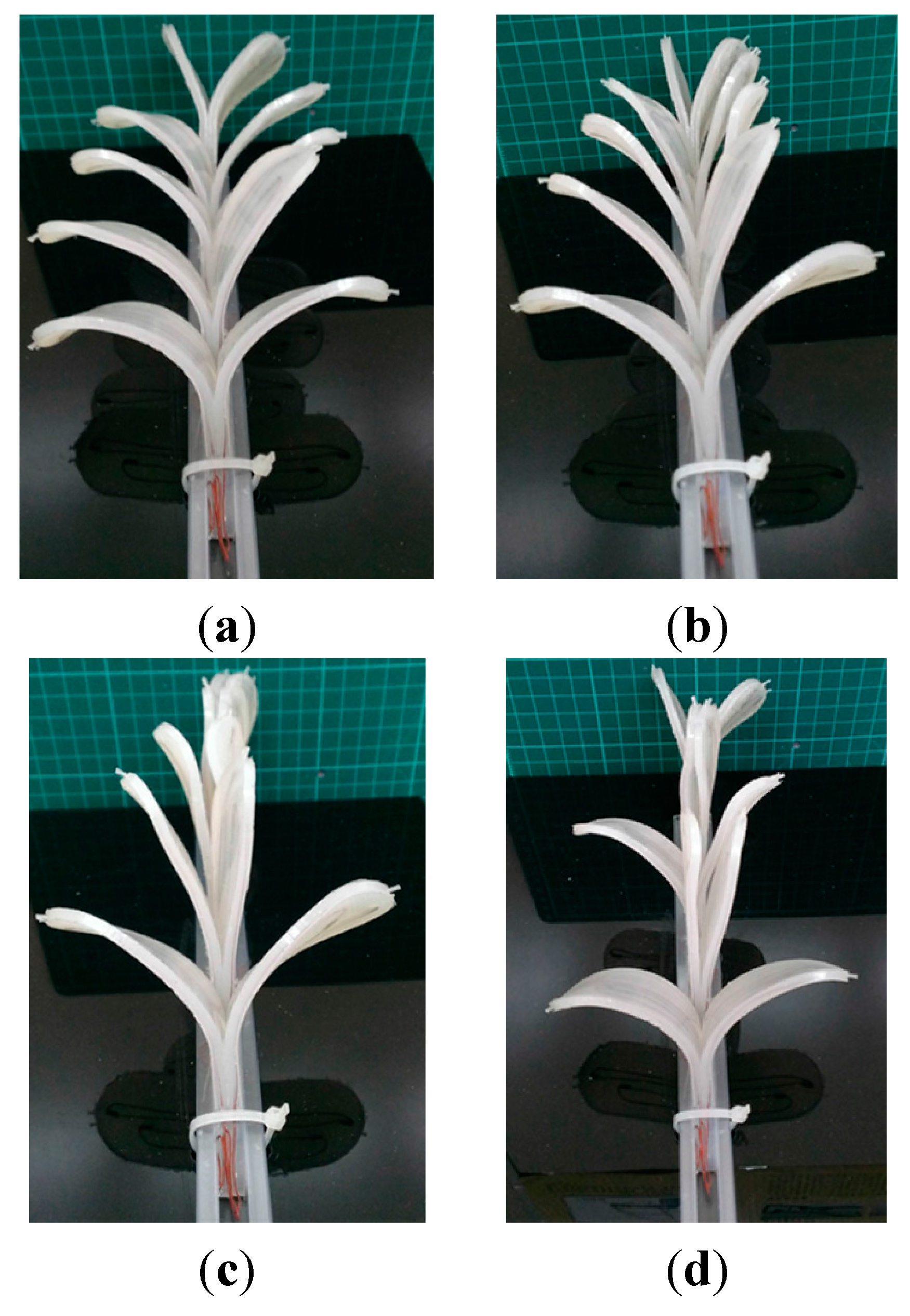
3.2.2. Bionic Mimosa Situational Behavior Swinging

This section illustrates the situational behaviors of a bionic mimosa, including Mode 1, Mode 2, and Mode 3. The three situational behaviors are the opening/closing behaviors after introduction of fuzzy control, and according to environmental factors. Figure 17a–c illustrate the shapes of plant strains in the case of Modes 1, 2, and 3, respectively.
According to the values of different environments or adjustments of human factors, the desired closing/opening types are designed. Figure 17d shows the self-designed display.
Figure 17. Mimosa system display Modes: (a) Mode 1; (b) Mode 2; (c) Mode 3; and (d) self-defined Mode.
Micromachines 06 00042 g017

3.3. Discussion

In this section, the leaf delicacy process, fuzzy control performance, and strain swing behaviors are analyzed and discussed.

3.3.1. Leaf Delicacy Process

The leaf designed in this study is a completely artificial leaf; thus, due to various factors, such as leaf area, characteristics of materials used, and bending degree of SMA subject to heat, a leaf with the ability to completely close cannot be obtained in the creation process (the statistics shows that the yield rate is about 85%). The cause for such failure is that two SMAs share the same memory direction. In other words, the leaf can swing only in one direction, thus, the arrangement and adjustment of the memory direction of SMA is an area for improvement in future micro-processing approach studies.

3.3.2. Fuzzy Control Performance

The fuzzy logical decision-making rule implemented in this study is derived from several experiments, through which the mimosa can show three swing behaviors. The design can reduce the number of fuzzy subsets and rule base, which decreases the complexity of fuzzy calculation and allow it to be more easily realized in the micro-controller. However, if more mode changes (only three modes now) are required, the controller number should be adjusted, and the psychological mode of the mimosa should be involved.

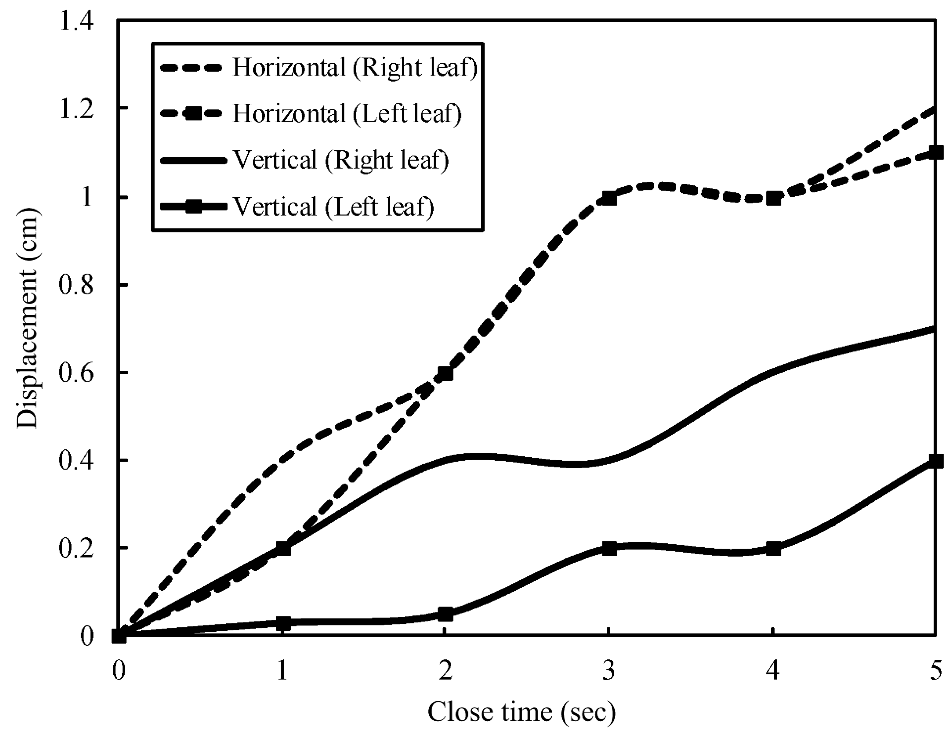
3.3.3. Strain Swing Behaviors

A total three swing modes are designed for the leaf. The swing position and direction of these three modes are preset and finalized after several adjustments. Our future study will construct a mathematical model based on the psychological mathematical model of a mimosa and the non-linear thermodynamic model of the SMA. More strains and environmental sensors will be added, and movable joints will be designed on leaf trunks and branches. In this way, the mimosa robot will be more lifelike and have better interaction.

4. Conclusions

This study developed SMA as the micro-actuation component for application in a mimosa vein. Regarding the processing and production of SMAs, through wire masking and annealing technology, this study realized the ideal wire diameter of the SMA, where SMA heating was realized by the direct heating memory method. The connection of the wire and SMA was realized by a DuPont joint that replaces the traditional soldering technique. Using two SMAs for different actuation directions can directly result in two-way bending of leaves, and the three-dimensional design of the leaf is more consistent with the actual shape of the mimosa.
Regarding the implementation of a control system, this study established a bionic mimosa situational mode, and determined the amount of environmental factors through fuzzy logic procedures. Finally, plant opening/closing situations were controlled by defuzzification. The proposed method can be applied in analysis of diverse systems and mode establishment. The entire experimental process was demonstrated by three modes, where each pair of leaves displayed different closing/opening postures according to different time durations for opening and closing. Users may choose manual or automatic modes according to different initial environmental settings in order to design different opening/closing display postures. The proposed method can be applied in micro-bionic robot systems, entertainment robots, biomedical engineering, and building aesthetics-related fields.

Acknowledgments

The authors appreciate the comments of the editor and reviewers. This study was financially sponsored by the Ministry of Science and Technology under Grant No. MOST 103-2221-E-020-041.

Author Contributions

The original concept and methods in research were provided by Chung-Liang Chang; he also wrote the paper, designed of experiments and supervised the work at all stages. The model simulation, measurements, and data analysis were performed by Jin-Long Shie. Both authors have read and approved the final manuscript.

Conflict of Interests

The authors declare no conflict of interests.

References

  1. Steele, J.E. How do we get there. In Bionics Symposium: Living Prototypes—The Key to New Technology; Gray, C.H., Ed.; Routledge: New York, NY, USA, 1995; pp. 55–60. [Google Scholar]
  2. Abbott, J.; Nagy, Z.; Beyeler, F.; Nelson, B. Robotics in the small. IEEE Robot. Autom. Mag. 2007, 14, 92–103. [Google Scholar] [CrossRef]
  3. Firebaugh, S.; Piepmeier, J.; Leckie, E.; Burkhardt, J. Jitterbot: A mobile millirobot using vibration actuation. Micromachines 2011, 2, 295–305. [Google Scholar] [CrossRef]
  4. Bar-Cohen, Y. Electroactive Polymer (EAP) Actuators as Artificial Muscles: Reality, Potential, and Challenges, 2nd ed.; SPIE Press: Washington, DC, USA, 2004. [Google Scholar]
  5. Nishida, G.; Sugiura, M.; Yamakita, M.; Maschke, B.; Ikeura, R. Multi-input multi-output integrated ionic polymer-metal composite for energy controls. Micromachines 2012, 3, 126–136. [Google Scholar] [CrossRef]
  6. Callister, W.D., Jr. Materials Science and Engineering: An Introduction, 8th ed.; John Wiley and Sons: Hoboken, NJ, USA, 2009. [Google Scholar]
  7. Jani, J.M.; Leary, M.; Subic, A.; Gibson, M.A. A review of shape memory alloy research, applications and opportunities. Mater. Des. 2014, 56, 1078–1113. [Google Scholar] [CrossRef]
  8. Son, H.M.; Lee, Y.J. New variable focal liquid lens system using antagonistic-type SMA actuator. In Proceedings of the 4th International Conference on Autonomous Robot and Agents, Wellinfton, New Zealand, 10–12 February 2009.
  9. Makishi, W.; Matunaga, T.; Haga, Y.; Esashi, M. Active bending electric endoscope using shape memory alloy coil actuator. In Proceedings of the First IEEE/RAS-EMBS International Conference on Biomedical Robotics and Biomechatronics, Pisa, Italy, 20–22 February 2006; pp. 217–219.
  10. Lee, Y.P.; Kim, B.; Lee, M.G.; Park, J.O. Locomotive mechanism design and fabrication of biomimetic micro robot using shape memory alloy. In Proceedings of the IEEE International Conference on Robotics and Automation, Seoul, Korea, 26 April–1 May 2004.
  11. Liu, C.Y.; Liao, W.H. A snake robot using shape memory alloys. In Proceedings of the 2004 IEEE International Conference on Robotics and Biomimetics, Shenyang, China, 22–26 August 2004.
  12. Zhang, Y.; Li, S.; Ma, J.; Yang, J. Development of an Underwater Oscillatory Propulsion System Using Shape Memory Alloy. In Proceedings of the IEEE International Conference on Mechatronics & Automation, Niagara Falls, NY, USA, 29 July–1 August 2005; pp. 1878–1883.
  13. Liu, Y.L.; Chung, A.; Hu, J.; Lv, J. Shape memory behavior of SMPU knitted fabric. J. Zhejiang Univ. Sci. A 2007, 8, 830–834. [Google Scholar] [CrossRef]
  14. Mingallon, M.; Ramaswamy, S. Bio-inspired self-actuating composite materials. In Composites and Their Applications; Ning, H., Ed.; InTech: Rijeka, Croatia, 2012. [Google Scholar]
  15. Huang, H.L.; Park, S.H.; Park, J.O.; Yun, C.H. Development of Stem Structure for Flower Robot using SMA Actuators. In Proceedings of the IEEE International Conference on Robotics and Biomimetics, Sanya, China, 15–18 December 2007; pp. 1580–1585.
  16. Chang, C.L.; Sie, M.F.; Shie, J.L. Development of a multisensor-based bio-botanic robot and its implementation using a self-designed embedded board. Sensors 2011, 11, 11629–11648. [Google Scholar] [CrossRef] [PubMed]
  17. Lee, C.C. Fuzzy logic in control system: Fuzzy logic controller. I. IEEE Trans. Syst. Man Cybern. 1990, 20, 404–418. [Google Scholar] [CrossRef]
  18. Lee, C.C. Fuzzy logic in control system: Fuzzy logic controller. II. IEEE Trans. Syst. Man Cybern. 1990, 20, 419–435. [Google Scholar] [CrossRef]
  19. Otsuka, K.; Wayman, C.M. Shape Memory Materials; Cambridge University Press: Cambridge, UK, 1998. [Google Scholar]
  20. Chang, C.L.; Shie, J.L. Design and implementation of actuator for the swing mechanism of interactive bio-mimosa robot. J. Chin. Soc. Mech. Eng. 2013, 34, 137–142. [Google Scholar]
  21. Lotters, J.C.; Olthuis, W.; Veltink, P.H.; Bergveld, P. The mechanical properties of the rubber elastic polymer polydimethylsiloxane for sensor applications. J. Micromech. Microeng. 1997, 7, 145–147. [Google Scholar] [CrossRef]
  22. McDonald, J.C.; Duffy, D.C.; Anderson, J.R.; Chiu, D.T.; Wu, H.; Schueller, O.J.A.; Whitesides, G.M. Fabrication of microfluidic devices using poly(dimethylsiloxane). Electrophoresis 2000, 21, 27–40. [Google Scholar] [CrossRef] [PubMed]
  23. Parallax Inc. BASIC Stamp. Available online: http://www.parallax.com/microcontrollers/basic-stamp (access on 5 June 2014).

