1. Introduction
Metal microdroplet deposition manufacture is a prospective additive manufacturing (AM) technology for fabricating 3D metal functional parts. Comparing to other metal additive manufacturing technologies, it possesses the obvious advantage of the lower cost of equipment. During deposition, the metal material is firstly melted in a crucible, and then the liquid metal droplets are ejected from a nozzle under the combined actions of pulse pressure, surface tension, and gravity. Finally, the molten droplets are deposited on a moving substrate to form 3D metal components. Although several metal droplet-based rapid prototyping systems have been developed in recent years to fabricate functional parts, some problems still exist that need to be solved urgently, such as the poor metallurgical bonding between droplets, micro-void, cold clap, etc. These problems severally affect the quality and accuracy of the fabricated parts.
To fabricate functional parts, especially free-standing sections of metal, by depositing molten metal droplets, it is essential to achieve a comprehensive understanding of the complex physical phenomena during droplet impingement, so as to control the individual molten droplets and ensure metallurgical bonding between metal droplets. Molten metals have high surface tension, melting temperature, latent heat of solidification, and thermal conductivity. If the temperature at the interface between the presolidified surface and impinging droplet is too low, droplets will bounce off; if it is too high they will not solidify but flow down. Beside, some other physical phenomena, such as oscillations, remelting, cooling, and solidifying of metal microdroplets, also have important influences on the forming accuracy and quality.
In addition, as a versatile direct 3D metal structuring approach, metal nanoparticles (NPs) have drawn significant interest in the area of low-temperature metal direct patterning by inkjet printing. Metal NPs exhibit low melting temperature due to the thermodynamic size effect, and can form a metal structure without driving the processing temperature above the bulk metal melting temperature. These attributes enable metal NP inkjet printing to possess substantial potential for the fabrication of electronic devices on plastic substrates. Fuller
et al. [
1] and Chung
et al. [
2] demonstrated inkjet printing of 2D electrical circuits and 2D MEMS (micro-electro-mechanical system) structures by inkjet printing of gold NP ink. Low-temperature 3D metal structure fabrication using metal NP inkjet printing was carried out by Carmen
et al. [
3] and Ko
et al. [
4,
5,
6].
There exists a considerable literature describing the numerical models of droplet impact on a solid surface. Early work by Harlow and Shannon [
7] used a “marker-and-cell” (MAC) method to solve the fluid mass and momentum conservation equations, neglecting the effect of viscosity and surface tension. Trapaga and Szekely [
8] used a commercial code, Flow-3D
® (Flow Science, Inc., San Diego, CA, USA), to study the isothermal impact of a lead droplet in a thermal spray process. Another volume of fluid (VOF) based code, RIPPLE, adopted by Huimin
et al. [
9], simulated molten metal droplet impact. There are some widely used methods aiming at phase change problems, such as enthalpy methods, temperature based equivalent heat capacity methods, and front tracking schemes. Escure
et al. [
10] investigated the impact process of aluminum droplets on cold and hot substrates by numerical modeling and experimental research. Fang
et al. [
11] predicted suitable temperatures of droplet and substrate to obtain good metallurgical bonding of droplets. Nevertheless, most of the numerical simulations listed above only modeled the same phenomenon—the normal impact of a single droplet on a flat and solid surface—and assumed that fluid flow is axisymmetric. In addition, the shrinkage effect caused by the density discrepancy between liquid and solid materials is not considered, a no-slip wall is employed instead of a more realistic boundary condition, and the possibility of air entrapment between splat and substrate is ignored.
During metal droplet manufacturing, the pileup process of molten droplets is more complex and of practical significance because the molten microdroplet experiences a drastic change in morphology due to the presolidified droplets. Unfortunately, there is limited information reported in the literature about the droplet impact on non-flat substrates [
12] and pileup process [
13,
14,
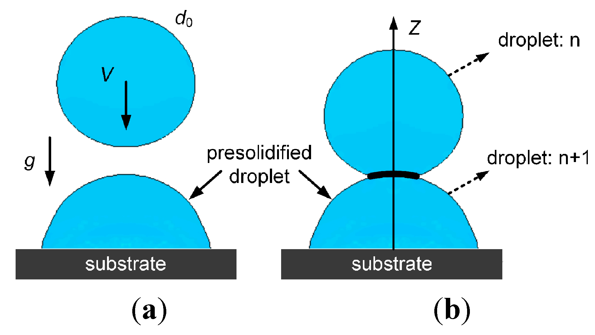
15]. The evolution of droplet morphology is shown in
Figure 1, where the droplet impacts onto the substrate vertically.
Figure 1.
Schematic of the pileup process in metal droplet manufacturing. (a) An impinging droplet will be deposited on the top of a solidified droplet perpendicularly. (b) Spreading and solidifying of the impacted droplet on the presolidified droplet.
Figure 1.
Schematic of the pileup process in metal droplet manufacturing. (a) An impinging droplet will be deposited on the top of a solidified droplet perpendicularly. (b) Spreading and solidifying of the impacted droplet on the presolidified droplet.
In order to achieve good forming accuracy, it is necessary to predict flow and solidification behavior between metal droplets. In this paper, a three-dimensional numerical model of flow and heat transfer was established to analyze the appropriate forming condition for achieving good metallurgical bonding between liquid metal microdroplets. Deposition experiments were performed to verify the accuracy of the numerical model. More specifically, the work is focused on the process where a molten droplet impacts on a previously impacted and solidified (or solidifying) droplet. The flow and thermal behavior at the interface of droplets were predicted and analyzed under different process parameters. The effects of impacting velocity and relative distances of successive two droplets on the end-shapes of the pileup were analyzed. The research results provide us with some physical insight into the complex behavior of liquid metal microdroplet deposition manufacture.
3. Experimental Validation of the Numerical Model
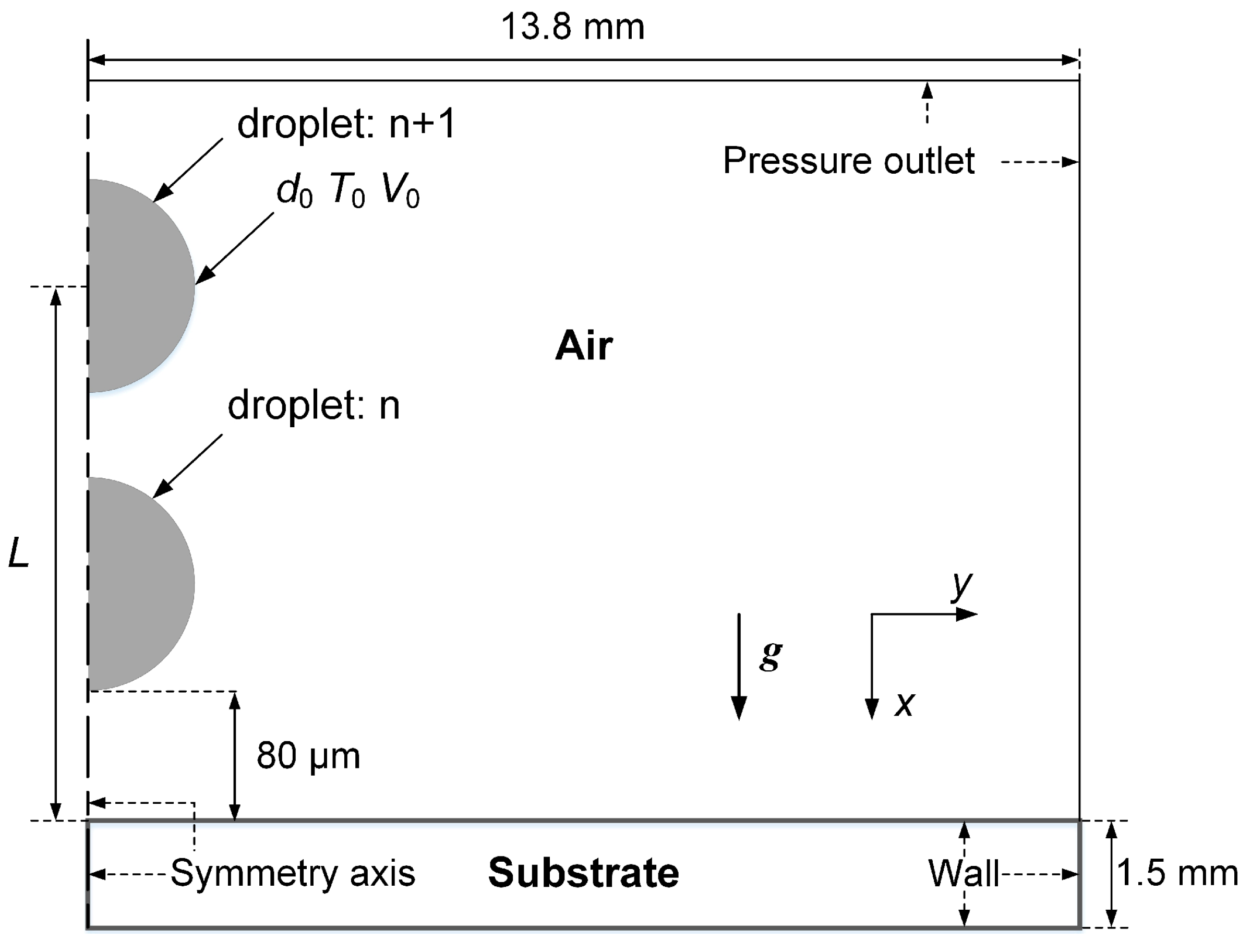
To validate the numerical model, experimental observation of the end-shapes of pileups was performed to compare and validate the numerical results. Aluminum alloy droplets having a diameter of 100 μm and an initial temperature of 960 K were generated with the DoD jetting at a rate of 5 Hz and successively deposited onto an H13 stainless steel substrate; the relevant thermo-physical parameters of the molten droplet and the substrate material are listed in
Table 2. Argon gas pulse was used as the driving force. A mass of 25 g aluminum alloy billet was placed in a graphite crucible. A spray nozzle with 73 μm diameter was located at the bottom of the crucible, which was built in a resistance furnace. The deposition experiment was performed in a glove box under an inert atmosphere with low oxygen content (no more than 5 ppm). The argon gas pulses, with a pressure of 40–90 kPa and a duration time of 1–1.5 ms, were imposed by a solenoid value onto the molten metal. Thus the uniform molten droplets were ejected out of the nozzle. The distance from the nozzle to the substrate was 18 mm, where the morphology and dynamic behavior of the molten droplets tend to be stable. The substrate was fixed and heated to about 350 K. The end-shapes of the solidified droplets were examined using a scanning electron microscope (SEM, VEGA III LMH, TESCAN, Brno, Czech Republic). For all experiments, the droplet diameters were kept at a size of approximately 100 μm because at this size the most stable droplet generation was obtained. The initial drop diameter in the experiments was measured by integrating Nikon AF Micro 200 mm f/4D IF-ED (Nikon Corporation, Tokyo, Japan) and Monarch Nova-Strobe BBX 115/230 Digital Portable Stroboscope (Monarch Instrument, South Burlington, VT, USA).
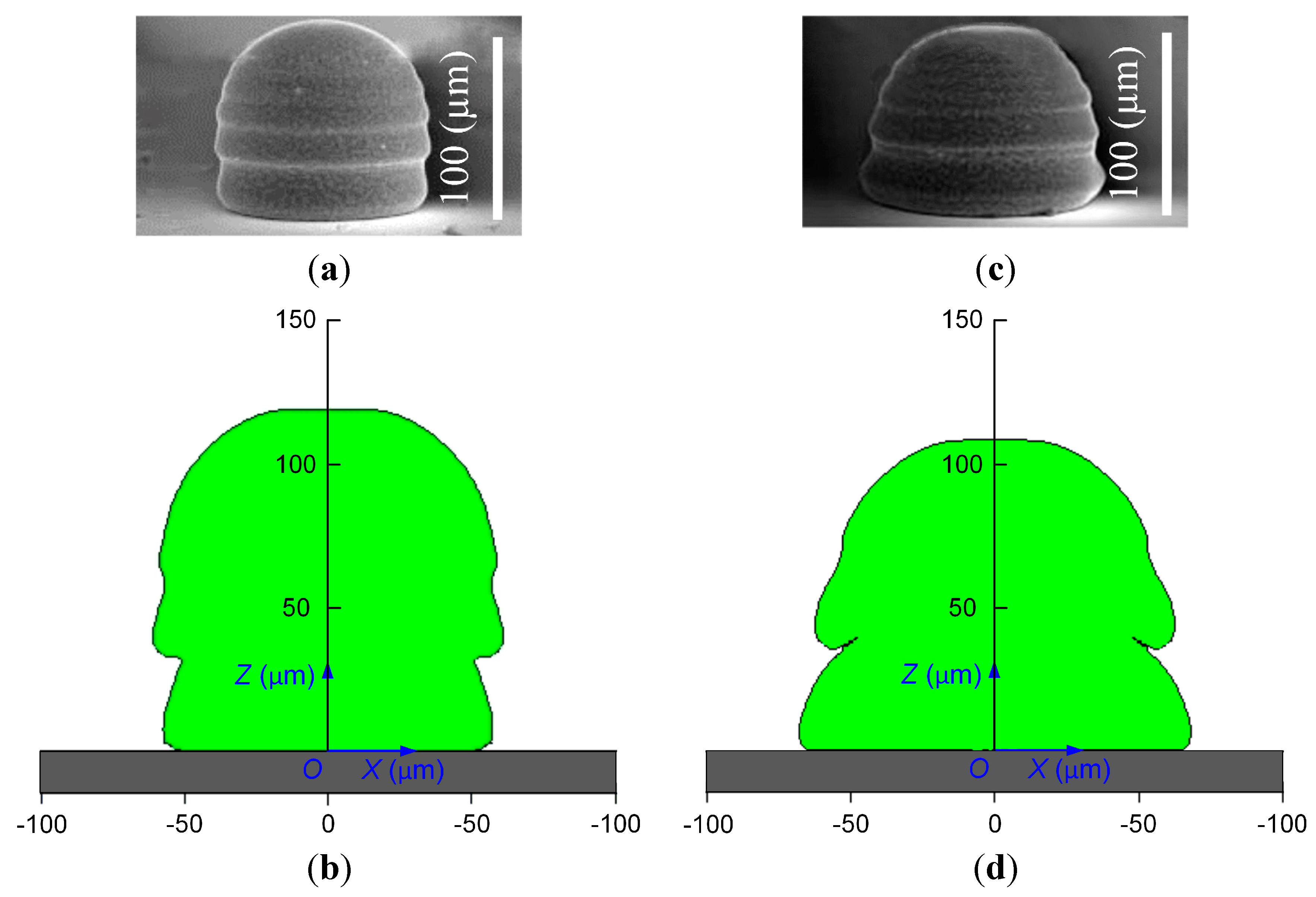
Figure 3 shows comparisons between photographs and computer model predictions for solidified pileup shape. The results show good qualitative agreement with experimental photographs.
Figure 3.
Comparison of SEM photo and simulation results of two 100-μm diameter aluminum alloy droplets impacting on a H13 stainless steel substrate: (a) pileup endshape with a velocity of 1.5 m/s, the droplet spacing is 200 μm; (b) simulated pileup endshape with a velocity of 1.5 m/s, the droplet spacing is 200 μm; (c) pileup endshape with a velocity of 2.5 m/s, the droplet spacing is 260 μm; (d) simulated pileup endshape with a velocity of 2.5 m/s, the droplet spacing is 260 μm.
4. Results and Discussion
Figure 4 and
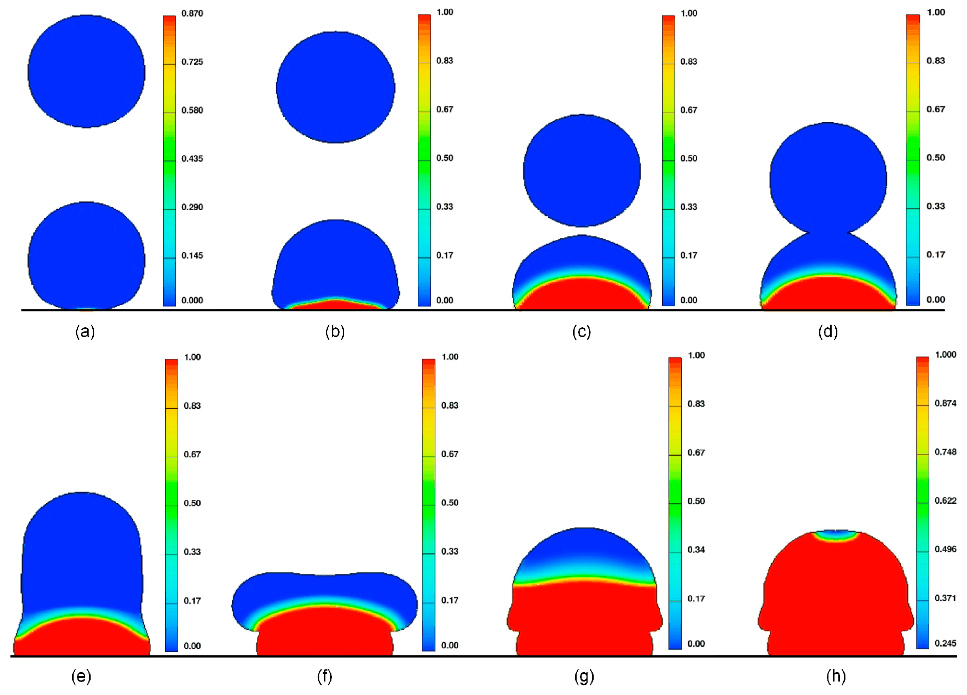
Figure 5 show the axisymmetric cross-section of the 3D deformation and solidification sequence of two successive droplets impinging onto a stainless steel substrate with impact velocity of 2.5 and 1.5 m/s. In the pileup process, surface tension forces resist and viscous forces damp the spreading process. Concurrently, solidification influences the spreading process as well. This can take place by solidification at the wetting line or by annihilation of kinetic energy by solidification.
In the early stage of pileup (
Figure 4a–c), the behavior of the droplet was similar to that of a single molten droplet during normal impacting, with symmetric spreading of melt about the point of impact. When the second drop comes in contact with the first one (
Figure 4d), if the first droplet is incompletely solidified at this moment, then the melt of the first one will merge with that of the second droplet; the melt after coalescence will continually spread under the action of the initial momentum of the second one. Therefore, it can be seen that the second drop spreads more than the first one at the initial contact stage (
Figure 5e–h). There are many ripples in the upper part of the solidified droplet. The ripples were the direct results of layered solidification and oscillation consisting of the alternate spreading and recoiling of the droplet. However, the symmetry in the whole pileup process was retained until the droplets completely solidified (
Figure 5h). In the process of droplet deposition, the temporal evolution of the contact area led concurrently to different cooling rates of the impinging droplet (
Figure 4). If the interfacial temperature between previously-deposited droplets and a new incoming droplet is too low, the remelting and coalescing of successive metal droplets are insufficient and forming defects (such as micro-void and cold lap) of deposition components may not be avoided.
In metal microdroplet deposition manufacture, forming accuracy and quality can be directly reflected in the morphological characteristics and metallurgical defects (such as micro-void and cold lap) of the pileups, respectively. To obtain better quantitative results, four series of numerical experiments were performed to investigate the interactions between impacting droplets and the previous droplets (totally solidified or not), and the influence of the impact velocity, droplet size, and substrate temperature on the end-shapes of the pileup was analyzed.
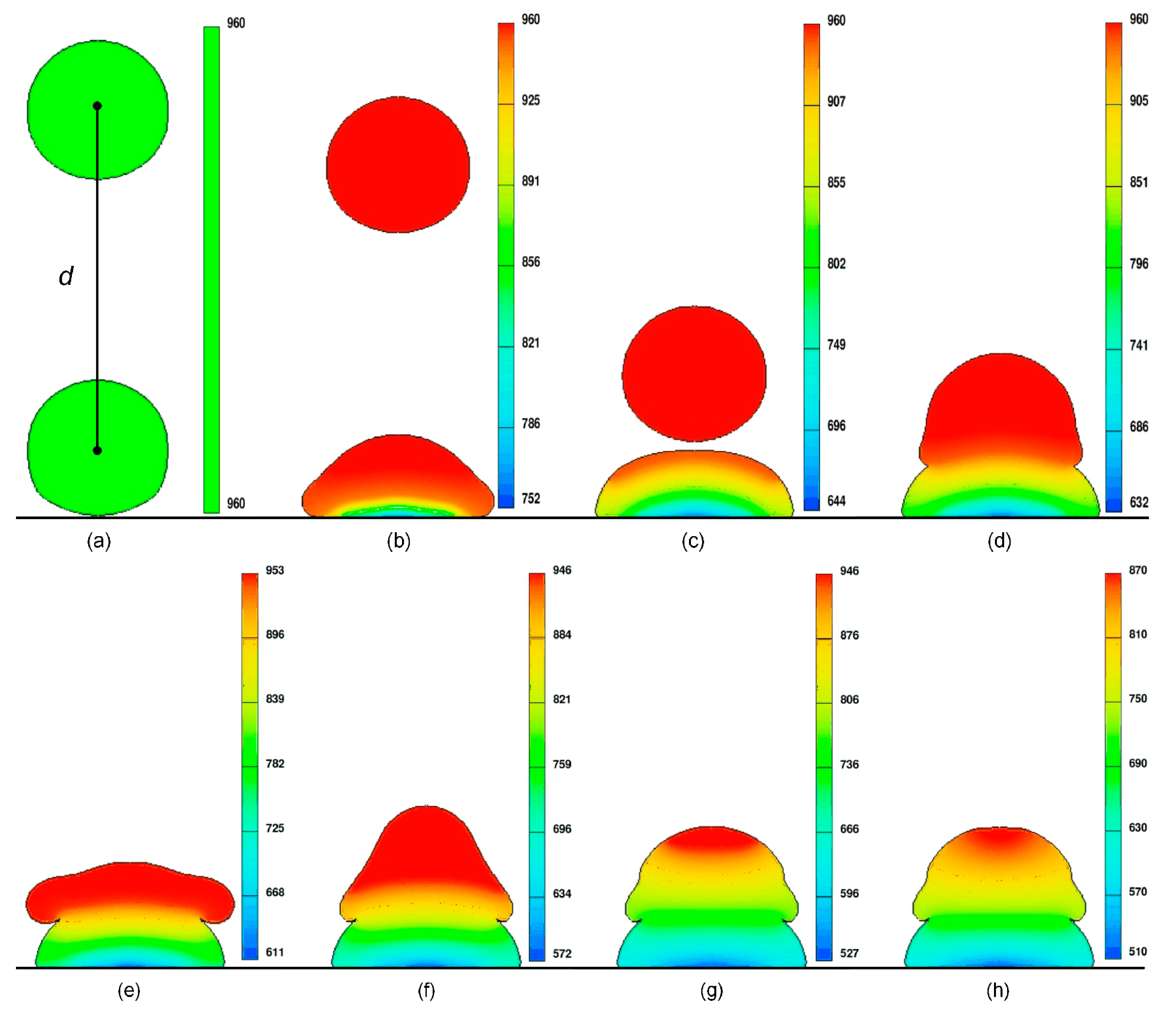
Figure 4.
Simulated deformation and temperature distribution of a 100-μm diameter aluminum alloy droplet, initially at 960 K, and its impingement on a stainless substrate at a velocity of 2.5 m/s; the distance between the two successive droplets is 240 μm and time is measured from the moment of impact: (a) t = 0 μs; (b) t = 15.5 μs; (c) t = 71.3 μs; (d) t = 83.7 μs; (e) t = 102.3 μs; (f) t = 158.1 μs; (g) t = 241.8 μs; and (h) t = 272.8 μs.
Figure 5.
Simulated deformation and solidification of a 100-μm diameter aluminum alloy droplet, initially at 960 K, and its impingement on a stainless substrate at a velocity of 1.5 m/s; the distance between the two successive droplets is 160 μm and time is measured from the moment of impact: (a) t = 0 μs; (b) t = 9.2 μs; (c) t = 55.2 μs; (d) t = 59.8 μs; (e) t = 73.6 μs; (f) t = 119.6 μs; (g) t = 239.2 μs; (h) t = 391 μs.
4.1. Influence of Impact Velocity
Quantitative information about the solidification can thus be extracted from the motion of the droplet by monitoring the largest circumference the droplets attain, droplet height, and the location of the solidification front.
Figure 6 shows the variation of the largest circumference the droplets attain, droplet height, and the location of the solidification front during droplet impact on a H13 stainless steel surface at 350 K for impact velocities from 1 to 3 m/s. The set of pileup cases in
Figure 6 shows the evolution process of pileup structures. The distance between two successive droplets is 220 μm. The effect of impact velocity on flow dynamics is visible. Each row in
Figure 6 represents the same dimensionless time
t* =
tV0/
D0; the real time (
t) from the instant of impact is directly adjacent to each frame.
At a low impact velocity
V0 = 1 m/s (
Figure 6a), the droplet reached its maximum spread diameter a little after
t* = 1.72. The melt was pulled back by surface tension, and recoil phenomena occurred at
t* = 1.94. The droplet finally subsided and solidified to form a rounded pileup (
t* = 6.91). Increasing the impact velocity to 2 m/s (
Figure 6b) and 3 m/s (
Figure 6c) increased the largest circumference the droplets attain and decreased the solidified height.
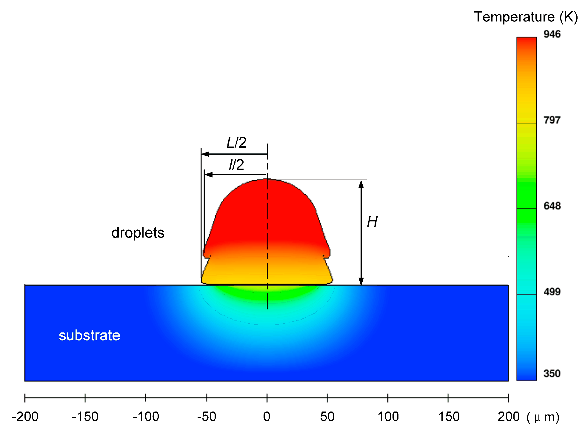
To quantitatively describe the morphological evolution of molten droplets and reveal the prevailing physical mechanisms in the process of pileup, the pileup process is divided into two stages. The first stage consists only of considering the previous molten droplet’s impact on the substrate. In the second stage, the merging of two successive droplets and the interaction of a droplet with the previous one are analyzed. Some feature sizes can be used to characterize the morphology of the solidified or solidifying droplets, just as shown in
Figure 7:
L and
l are the largest circumferences of the previously solidified droplet and second droplet, respectively, and
H is the droplet height at the impact location.
Figure 6.
Impact of molten aluminum alloy droplet on a stainless steel surface at temperature 350 K with velocity (a) 1 m/s, (b) 2 m/s, and (c) 3 m/s; the distance between the two successive droplets is 220 μm.
Figure 6.
Impact of molten aluminum alloy droplet on a stainless steel surface at temperature 350 K with velocity (a) 1 m/s, (b) 2 m/s, and (c) 3 m/s; the distance between the two successive droplets is 220 μm.
Figure 7.
Simulated deformation and temperature distribution of 100-μm diameter aluminum alloy droplets, initially at 960 K, and their impingement on a stainless substrate at t = 202 μs; impact velocity is 3 m/s and the distance between the two successive droplets is 280 μm.
Figure 7.
Simulated deformation and temperature distribution of 100-μm diameter aluminum alloy droplets, initially at 960 K, and their impingement on a stainless substrate at t = 202 μs; impact velocity is 3 m/s and the distance between the two successive droplets is 280 μm.
Figure 8 shows the temporal evolution of dimensionless largest circumference the droplets attain and dimensionless height as a function of the impact velocities. The droplets feature impact velocities in the range of 1–3 m/s with the same diameter of 100 μm. Due to the different impact velocities (impact kinetic energy), this leads to a significant difference between the largest circumferences of the first droplet and the second one.
Figure 8.
Temporal evolution of (a) dimensionless largest circumference and (b) dimensionless height during impacting of a molten aluminum alloy droplet on a stainless steel surface at temperature 350 K with velocity 1–3 m/s; the distance between the two successive droplets is 220 μm.
Figure 8.
Temporal evolution of (a) dimensionless largest circumference and (b) dimensionless height during impacting of a molten aluminum alloy droplet on a stainless steel surface at temperature 350 K with velocity 1–3 m/s; the distance between the two successive droplets is 220 μm.
When comparing the values of the largest circumference the droplets attain for the present pileup cases in
Figure 8, it is apparent that the dependence of the difference between the largest circumference and the corresponding final splat diameter on the impact velocity is not monotonic. In the first stage, solidification occurred as soon as the impinging molten droplet contacted the substrate. The rate of solidification was fastest around the rim of the spreading droplet, where it first contacted the colder substrate, and the melt began to solidify there. The melt flow was obstructed by the solidified layer around the spreading rim. In the meantime, surface tension pulls back the melt, which makes the molten layer recoil toward the center of the splat. The melt above the solidification front oscillated back and forth vertically, which made the free surface of the melt achieve a partial rebound. From
Figure 8, it was also found that once the largest circumference the droplets attain reaches a maximum value it begins to decrease as droplets recoil; the dimensionless largest circumference and the final splat diameter of the presolidified droplet increase nonlinearly with an increasing impact velocity. However, the difference between the dimensionless largest circumference and the final splat diameter of the presolidified droplet is not monotonic, decreasing with the increase of impact velocity, whereas the amplitude of free surface rebound in the vertical direction decreases with increasing impact velocity.
In the second stage, when an incoming droplet comes in contact with the previously solidifying droplet, the thermal field and flow field were rapidly perturbed under the impact location and the location where the two droplets achieve coalescence. Although the incoming droplets have the same impact velocity, the meeting time of the two droplets depends on the instantaneous height of the free surface of the first droplet. After meeting, the oscillation-induced inertial pressure changes alternately spread and force the liquid close to the solidification front to recoil; the solidification front advances continually from the solidification front of the previously solidifying droplet into the oscillating liquid, which left a series of ripples on the surface of the splat (
Figure 3). Combined with the results described in
Figure 8, it can be seen clearly that the effective contact area at the solidification front is significantly increased with the increase of impact velocity from 1 to 3 m/s at the same dimensionless time. Most of the kinetic energy of the melt is lost due to solidification and overcoming viscosity.
4.2. Influence of the Distance between Two Successive Droplets
Besides the impact velocity, the distance between two successive droplets
d is another important parameter that significantly influences the pileup morphology.
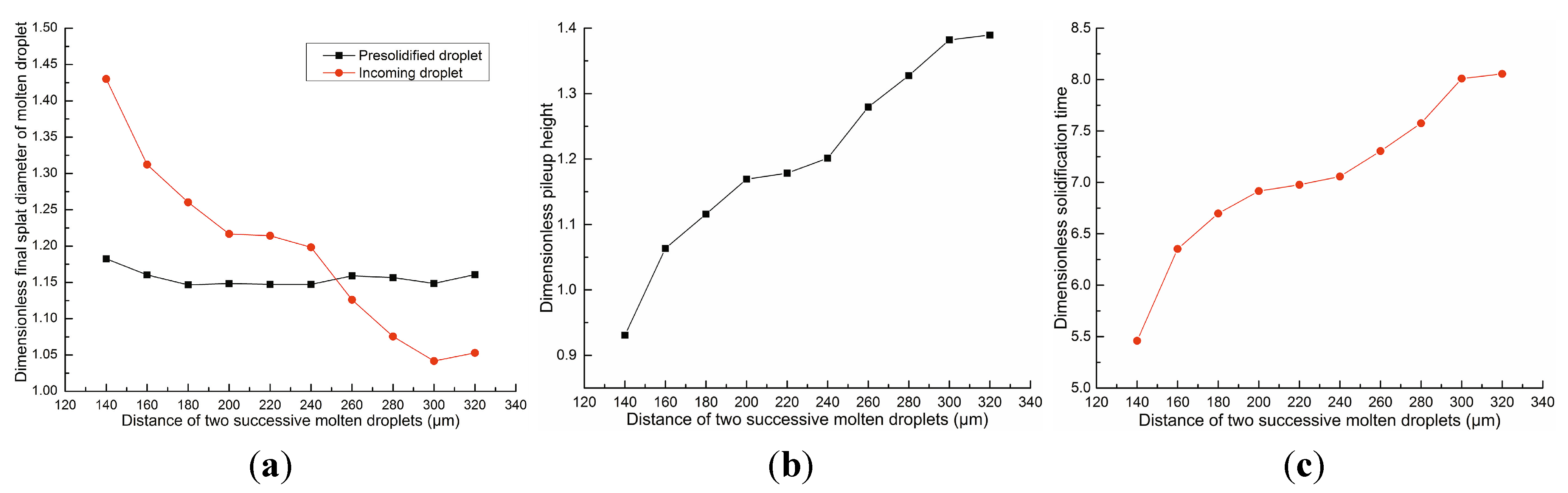
Figure 9 shows the variation of the dimensionless height and final splat diameter of aluminum alloy molten droplets after complete solidification; the droplet’s diameter with an impact velocity of 1.5 m/s is 100 μm, the surface temperature of the stainless steel substrate is 350 K, and the distance between the two successive droplets ranges from 140 to 320 μm.
Figure 9.
Variation in (a) dimensionless final splat diameter, (b) dimensionless pileup height, and (c) dimensionless solidification time with the distance between two successive droplets.
Figure 9.
Variation in (a) dimensionless final splat diameter, (b) dimensionless pileup height, and (c) dimensionless solidification time with the distance between two successive droplets.
The impact fluid dynamics, cooling, and subsequent solidification of the second droplet in the pileup is strongly influenced by the geometry of the first, solidifying droplet. For droplet spacing ranging from 140 to 320 μm, the dimensionless pileup height changes from about 0.93 to nearly 1.39 (
Figure 9b) and the dimensionless solidification time changes from 5.46 to 8.06 (
Figure 9c). The dimensionless final splat diameter of the incoming droplet varies from about 1.43 to nearly 1.05, but the dimensionless final splat diameter of the predeposited droplet ranges from 1.15 to 1.18 (
Figure 9a). As droplet spacing decreases, the droplets coalesce sooner. There is a fairly narrow operating window in which the final splat diameter of aluminum alloy molten droplets has a good consistency. The dimensionless pileup height and solidification time depend non-monotonically on the droplet spacing.
During the sequential impact of droplets, thermal phenomena can be described according to the temperature at specific locations inside the substrate.
Figure 10 illustrates the temporal evolution of the temperature picked up in the substrate, under impact positions at different depth
z1,
z2, and
z3. The substrate is initially held to
T = 300 K and the droplets are hot at
T = 960 K.
Figure 10.
Temperature history at specific position during the impact of successive droplets.
Figure 10.
Temperature history at specific position during the impact of successive droplets.
As the droplet spacing increases, merging of droplets is achieved with an appropriate delay time. The given times corresponding to the time instance when both droplets merge are 58, 70.5, and 89 μs, respectively. They are indicated as the vertical dotted lines shown in
Figure 10. Before each critical moment, there was no obvious difference in the temperature profile at specific locations. The slope of the temperature profile at the moment of impact of the second droplet is continuous. As the droplets continue to merge, the differences in temperature begin to appear. In general, the temperature at
z3 increases gradually as the temperature variation due to the impact of the second droplet is less marked at this depth than at
z1 and
z2. However, the temperatures at specific locations will continue to rise for a while because the second droplet supplies heat again to the substrate and thermal diffusion takes place in the substrate. From another point of view, the magnitude of temperature increase after merging is limited; this indicates that thermal exchange between droplets and substrate is obvious when the first droplet impacts onto the substrate. The supply of thermal energy by the second droplet has little influence upon the temperature increase of the substrate.
5. Conclusions
In this research, a 3D numerical model of flow and heat transfer was established to analyze the appropriate forming condition for achieving good metallurgical bonding between liquid metal microdroplets.
It is demonstrated that the established numerical model of the pileup process is in good accordance with the experimental data. These results include insight into how the end-shapes of pileups depend on the impact velocity and the distance between two successive droplets. Furthermore, an overview of the dynamic spreading behavior of molten microdroplets in the pileup process is developed. The dependence of the difference between the dimensionless largest circumference and the corresponding final splat diameter on the impact velocity is not linear, and the largest circumferences of the previously solidifying droplets are not always larger than the final splat diameter.
Additionally, an appropriate impact velocity and distance between two successive molten droplets for obtaining good metallurgical bonding among droplets and the desired component shape were ascertained.


