<?xml version="1.0" encoding="UTF-8"?>
<!DOCTYPE article PUBLIC "-//NLM//DTD Journal Publishing DTD v2.3 20070202//EN" "journalpublishing.dtd">
<article xmlns:mml="http://www.w3.org/1998/Math/MathML" xmlns:xlink="http://www.w3.org/1999/xlink" xml:lang="en" article-type="research-article">
  <front>
    <journal-meta>
      <journal-id journal-id-type="publisher-id">micromachines</journal-id>
      <journal-title>Micromachines</journal-title>
      <abbrev-journal-title abbrev-type="publisher">Micromachines</abbrev-journal-title>
      <abbrev-journal-title abbrev-type="pubmed">Micromachines</abbrev-journal-title>
      <issn pub-type="epub">2072-666X</issn>
      <publisher>
        <publisher-name>MDPI</publisher-name>
      </publisher>
    </journal-meta>
    <article-meta>
      <article-id pub-id-type="doi">10.3390/mi3020379</article-id>
      <article-id pub-id-type="publisher-id">micromachines-03-00379</article-id>
      <article-categories>
        <subj-group>
          <subject>Article</subject>
        </subj-group>
      </article-categories>
      <title-group>
        <article-title>A Hybrid Thermopneumatic and Electrostatic Microvalve with Integrated Position Sensing</article-title>
      </title-group>
      
      <contrib-group>
        <contrib contrib-type="author">
          <name>
            <surname>Potkay</surname>
            <given-names>Joseph A.</given-names>
          </name>
          <xref rid="af1-micromachines-03-00379" ref-type="aff">1</xref>
          <xref rid="c1-micromachines-03-00379" ref-type="corresp">*</xref>
        </contrib>
        <contrib contrib-type="author">
          <name>
            <surname>Wise</surname>
            <given-names>Kensall D.</given-names>
          </name>
          <xref rid="af2-micromachines-03-00379" ref-type="aff">2</xref>
        </contrib>
      </contrib-group>
      <aff id="af1-micromachines-03-00379"><label>1 </label>Advanced Platform Technology Center, Department of Veterans Affairs Medical Center, Cleveland, OH 44106, USA</aff>
      <aff id="af2-micromachines-03-00379"><label>2 </label>Department of Electrical Engineering and Computer Science, The University of Michigan, Ann Arbor, MI 48109, USA; Email: <email>wise@umich.edu</email></aff>
      <author-notes>
        <corresp id="c1-micromachines-03-00379"><label>*</label> Author  to whom correspondence should be addressed; Email: <email>joseph.potkay@case.edu</email>; Tel.: +1-216-904-5641; Fax: +1-216-707-6420.</corresp>
      </author-notes>
      <pub-date pub-type="epub">
        <day>27</day>
        <month>04</month>
        <year>2012</year>
      </pub-date>
      <pub-date pub-type="collection">
        <month>06</month>
        <year>2012</year>
      </pub-date>
      <volume>3</volume>
      <issue>2</issue>
      <fpage>379</fpage>
      <lpage>395</lpage>
      <history>
        <date date-type="received">
          <day>20</day>
          <month>03</month>
          <year>2012</year>
        </date>
        <date date-type="rev-recd">
          <day>17</day>
          <month>04</month>
          <year>2012</year>
        </date>
        <date date-type="accepted">
          <day>24</day>
          <month>04</month>
          <year>2012</year>
        </date>
      </history>
      <permissions>
        <copyright-statement>© 2012 by the authors; licensee MDPI, Basel, Switzerland.</copyright-statement>
        <copyright-year>2012</copyright-year>
        <license xmlns:xlink="http://www.w3.org/1999/xlink" license-type="open-access" xlink:href="http://creativecommons.org/licenses/by/3.0/">
          <p>This article is an open-access article distributed under the terms and conditions of the Creative Commons Attribution license (http://creativecommons.org/licenses/by/3.0/).</p>
        </license>
      </permissions>
      <abstract>
        <p>This paper presents a low-power hybrid thermopneumatic microvalve with an electrostatic hold and integrated valve plate position sensing. This combination of actuators in a single structure enables a high throw and force actuator with low energy consumption, a combination that is difficult to otherwise achieve. The completed 7.5 mm × 10.3 mm × 1.5 mm valve has an open flow rate of 8 sccm at 600 Pa, a leak rate of 2.2 × 10<sup>−3</sup> sccm at 115 kPa, a open-to-closed fluidic conductance ratio of nearly one million, an actuation time of 430 ms at 250 mW, and a required power of 90 mW while closed. It additionally requires no power to open, and has a built-in capacitive position sensor with a sensitivity of 9.8 fF/kPa. The paper additionally presents analytical models of the valve components, design tradeoffs, and guidelines for achieving an optimized device.</p>
      </abstract>
      <kwd-group>
        <kwd>microvalve</kwd>
        <kwd>thermopneumatic</kwd>
        <kwd>electrostatic</kwd>
        <kwd>low power</kwd>
        <kwd>μGC</kwd>
        <kwd>hybrid actuator</kwd>
      </kwd-group>
    </article-meta>
  </front>
  <body>
    <sec sec-type="intro">
      <title>1. Introduction</title>
      <p>Most portable microfluidic analysis systems require valving systems with similar performance requirements. Specifically, the valve for such systems should consume very little power to accommodate the use of a battery, have a throw (valve plate travel distance) greater than 30 μm to facilitate the passage of biological or chemical samples, be able to remain closed in the face of a large hold off pressure, and have a low leak rate, low dead volume, and fast response time. For the micro gas chromatography (μGC) system being developed in the National Science Foundation Engineering Research Center for Wireless Integrated MicroSystems (WIMS ERC) at The University of Michigan, the required valve specifications are shown in <xref ref-type="table" rid="micromachines-03-00379-t001">Table 1</xref>. In the past, it has been difficult to achieve valves with a large force, high open flow rate and low power, and this was the main challenge for this work.</p>
      <table-wrap id="micromachines-03-00379-t001" position="anchor">
        <object-id pub-id-type="pii">micromachines-03-00379-t001_Table 1</object-id>
        <label>Table 1</label>
        <caption>
          <p>Performance targets for the microvalve.</p>
        </caption>
        <table>
          <thead>
            <tr>
              <th align="left" valign="middle">Category</th>
              <th align="right" valign="middle">Requirement</th>
            </tr>
          </thead>
          <tbody>
            <tr>
              <td align="left" valign="middle">Energy Consumption</td>
              <td align="right" valign="middle">&lt;50 mJ/transition</td>
            </tr>
            <tr>
              <td align="left" valign="middle">Power Consumption</td>
              <td align="right" valign="middle">&lt;10 mW average</td>
            </tr>
            <tr>
              <td align="left" valign="middle">Open flow rate</td>
              <td align="right" valign="middle">&gt;5 sccm @ 500 Pa</td>
            </tr>
            <tr>
              <td align="left" valign="middle">Maximum differential pressure</td>
              <td align="right" valign="middle">&gt;50 kPa</td>
            </tr>
            <tr>
              <td align="left" valign="middle">Leak rate</td>
              <td align="right" valign="middle">&lt;0.01 sccm</td>
            </tr>
            <tr>
              <td align="left" valign="middle">Switching Time</td>
              <td align="right" valign="middle">&lt;500 ms</td>
            </tr>
            <tr>
              <td align="left" valign="middle">Valve clearance</td>
              <td align="right" valign="middle">&gt;30 μm</td>
            </tr>
            <tr>
              <td align="left" valign="middle">Size</td>
              <td align="right" valign="middle">&lt;0.25 cm<sup>3</sup></td>
            </tr>
          </tbody>
        </table>
      </table-wrap>
      <p>Numerous valve designs have been explored both in industry and academia [<xref ref-type="bibr" rid="B1-micromachines-03-00379">1</xref>,<xref ref-type="bibr" rid="B2-micromachines-03-00379">2</xref>]. Electrostatic actuators are very low power and have fast response times but are sensitive to particulates and have low clearance and low open flow. Electromagnetic valves can achieve good performance, but the forces scale unfavorably for devices with small volume. Piezoelectric actuators can exhibit large actuation forces and fast response times, but have low throw and require large voltages. Sol-gel based valves have achieved large volumetric displacement but usually require liquid for actuation. Thermopneumatic valves are robust and have high force and large throw but require continuous power to remain actuated.</p>
      <p>Attempts have been made to combine multiple actuation principles in hybrid or bistable designs with the goal of alleviating the drawbacks of a single actuation mechanism. In 1993, Bosch <italic>et al</italic>. developed a hybrid electromagnetic and electrostatic valve for low pressure applications that consumed 50 mW of power when actuated, had a 0.4 ms response time and a leak rate of 0.01 sccm [<xref ref-type="bibr" rid="B3-micromachines-03-00379">3</xref>]. In 1996 Wagner <italic>et al</italic>. investigated a valve based on two pneumatically-coupled membranes and electrostatic actuation [<xref ref-type="bibr" rid="B4-micromachines-03-00379">4</xref>]. When one electrode was pulled down electrostatically, the other was forced upward pneumatically. In 2000, Capanu <italic>et al</italic>. presented an electromagnetically-actuated valve with mechanical bistability, an open flow of 330 sccm at 6.2 kPa, and a response time of 38 ms, and requiring 380 mW to transition between states [<xref ref-type="bibr" rid="B5-micromachines-03-00379">5</xref>]. In 2004, Frank and Pisano reported a mechanically bistable valve with electrolysis actuation that required less than 1 mW to transition between states and had a leak rate of 0.002 sccm at 117 kPa, but required 10 s to close and had a low open flow rate [<xref ref-type="bibr" rid="B6-micromachines-03-00379">6</xref>]. In 2008, Shaikh <italic>et al</italic>. demonstrated a latching microvalve employing a low melting point metal alloy and pneumatic actuation [<xref ref-type="bibr" rid="B7-micromachines-03-00379">7</xref>]. The integrated heater enabled heating and cooling of the alloy in about 130 ms and complete closure to occur in about 400 ms. In general, each of these valves has advantages and disadvantages. A comparison of the performance of a representative subset of these valves is shown in <xref ref-type="table" rid="micromachines-03-00379-t002">Table 2</xref>.</p>
      
      <p>This paper reports a valve based on combined thermopneumatic and electrostatic actuators. Using this hybrid actuation scheme, the high force and large throw characteristics of thermopneumatic actuators are preserved, while the electrostatic hold reduces the energy requirement of the device. It is also shown that this combination can significantly improve the response time compared to a stand-alone thermopneumatic actuator. This work builds on previous work at Michigan on electrostatic actuators [<xref ref-type="bibr" rid="B11-micromachines-03-00379">11</xref>] and phase-change actuation [<xref ref-type="bibr" rid="B12-micromachines-03-00379">12</xref>]. Other thermopneumatic microvalves have been developed in the past. In 1997, Henning <italic>et al</italic>. presented a thermopneumatic microvalve capable of closing in 1 s at 450 mW [<xref ref-type="bibr" rid="B13-micromachines-03-00379">13</xref>]. In 2003, Rich and Wise presented a thermopneumatic microvalve capable of closing in 1.5 s at 350 mW and capable of maintaining closure at 30 mW of power [<xref ref-type="bibr" rid="B10-micromachines-03-00379">10</xref>]. The current device contains a heater with improved thermal isolation compared to previous devices and integrates an electrostatic actuator into the device to reduce the required hold power and increase speed. In addition, the current valve is an improved version of a device previously presented by the authors [<xref ref-type="bibr" rid="B14-micromachines-03-00379">14</xref>]. The current device has a more efficient heater design, a faster switching speed, a larger flow conductance, an improved latch design, and a lower leak rate than the prior device. <xref ref-type="table" rid="micromachines-03-00379-t003">Table 3</xref> describes these improvements in more detail. In addition, this manuscript presents a complete analytical model of the device and provides guidelines for design optimization.</p>
      <table-wrap id="micromachines-03-00379-t002" position="anchor">
        <object-id pub-id-type="pii">micromachines-03-00379-t002_Table 2</object-id>
        <label>Table 2</label>
        <caption>
          <p>Comparison of a representative subset of previous valve technologies. The data emphasizes the difficulty in achieving a large force and throw (large open flow and small leak conductance) valve with low power requirement and fast response time. Flows have been converted to conductances for easier comparison. N/A signifies that the data was not available in the paper. The best performance in each column is highlighted with bold text.</p>
        </caption>
        <table>
          <thead>
            <tr>
              <th align="center" valign="middle"> </th>
              <th align="center" valign="middle">Source</th>
              <th align="center" valign="middle">Open Flow Conductance (cm<sup>3</sup>s<sup>−1</sup>Pa<sup>−1</sup>) </th>
              <th align="center" valign="middle">Steady State Power (mW)</th>
              <th align="center" valign="middle">Response Time (ms)</th>
              <th align="center" valign="middle">Leak Conductance (cm<sup>3</sup>s<sup>−1</sup>Pa<sup>−1</sup>)</th>
              <th align="center" valign="middle">Type </th>
            </tr>
          </thead>
          <tbody>
            <tr style="border-top: solid thin">
              <td rowspan="3" align="center" valign="middle"><bold>Single Actuator Technology</bold></td>
              <td align="center" valign="middle">Yang [<xref ref-type="bibr" rid="B8-micromachines-03-00379">8</xref>]</td>
              <td align="center" valign="middle">4.2 × 10<sup>−7</sup></td>
              <td align="center" valign="middle">4</td>
              <td align="center" valign="middle">10</td>
              <td align="center" valign="middle">
                <bold>3.0 × 10<sup>−13</sup></bold>
              </td>
              <td align="left" valign="middle">Piezoelectric</td>
            </tr>
            <tr style="border-top: solid thin">
              <td align="center" valign="middle">Sihler [<xref ref-type="bibr" rid="B9-micromachines-03-00379">9</xref>] </td>
              <td align="center" valign="middle">2.0 × 10<sup>−6</sup></td>
              <td align="center" valign="middle">
                <bold>0 </bold>
              </td>
              <td align="center" valign="middle">N/A </td>
              <td align="center" valign="middle">6.4 × 10<sup>−11</sup></td>
              <td align="left" valign="middle">Electrostatic</td>
            </tr>
            <tr style="border-top: solid thin">
              <td align="center" valign="middle">Rich [<xref ref-type="bibr" rid="B10-micromachines-03-00379">10</xref>]</td>
              <td align="center" valign="middle">3.3 × 10<sup>−5</sup></td>
              <td align="center" valign="middle">30</td>
              <td align="center" valign="middle">1,000</td>
              <td align="center" valign="middle">3.1 × 10<sup>−10</sup></td>
              <td align="left" valign="middle">Thermopneumatic</td>
            </tr>
            <tr style="border-top: solid thin">
              <td rowspan="3" align="center" valign="middle"><bold>Hybrid / Bistable Technologies</bold></td>
              <td align="center" valign="middle">Bosch [<xref ref-type="bibr" rid="B3-micromachines-03-00379">3</xref>]</td>
              <td align="center" valign="middle">2.5 × 10<sup>−6</sup></td>
              <td align="center" valign="middle">50</td>
              <td align="center" valign="middle">
                <bold>0.4</bold>
              </td>
              <td align="center" valign="middle">1.7 × 10<sup>−8</sup></td>
              <td align="left" valign="middle">Electromagnetic; electrostatic</td>
            </tr>
            <tr style="border-top: solid thin">
              <td align="center" valign="middle">Capanu [<xref ref-type="bibr" rid="B5-micromachines-03-00379">5</xref>]</td>
              <td align="center" valign="middle">
                <bold>8.9 × 10<sup>−4</sup></bold>
              </td>
              <td align="center" valign="middle">
                <bold>0</bold>
              </td>
              <td align="center" valign="middle">38</td>
              <td align="center" valign="middle">N/A</td>
              <td align="left" valign="middle">Electromagnetic; mechanically bistable</td>
            </tr>
            <tr style="border-top: solid thin">
              <td align="center" valign="middle">Frank [<xref ref-type="bibr" rid="B6-micromachines-03-00379">6</xref>]</td>
              <td align="center" valign="middle">9.7 × 10<sup>−7</sup></td>
              <td align="center" valign="middle">
                <bold>0</bold>
              </td>
              <td align="center" valign="middle">10,000 </td>
              <td align="center" valign="middle">3.2 × 10<sup>−10</sup></td>
              <td align="left" valign="middle">Electrolysis; mechanically bistable</td>
            </tr>
            <tr style="border-top: solid thin">
              <td align="center" valign="middle"> </td>
              <td align="center" valign="middle">Current</td>
              <td align="center" valign="middle">2.2 × 10<sup>−4</sup></td>
              <td align="center" valign="middle">90 </td>
              <td align="center" valign="middle">430</td>
              <td align="center" valign="middle">3.2 × 10<sup>−10</sup></td>
              <td align="left" valign="middle">Thermopneumatic &amp; electrostatic</td>
            </tr>
          </tbody>
        </table>
      </table-wrap>
      <table-wrap id="micromachines-03-00379-t003" position="anchor">
        <object-id pub-id-type="pii">micromachines-03-00379-t003_Table 3</object-id>
        <label>Table 3</label>
        <caption>
          <p>Comparison to our previous work [<xref ref-type="bibr" rid="B14-micromachines-03-00379">14</xref>].</p>
        </caption>
        <table rules="rows">
          <thead>
            <tr>
              <th align="left" valign="middle">Category</th>
              <th align="left" valign="middle">Previous Design</th>
              <th align="left" valign="middle">Current Design</th>
            </tr>
          </thead>
          <tbody>
            <tr>
              <td align="left" valign="middle">Heater Design</td>
              <td align="left" valign="middle">Diamond grid structure; 10 μm elevation; Additional support posts decrease thermal isolation.</td>
              <td align="left" valign="middle">Ladder grid structure; 50 μm elevation; No additional support posts.</td>
            </tr>
            <tr>
              <td align="left" valign="middle">Switching Speed (ms)</td>
              <td align="left" valign="middle">1000</td>
              <td align="left" valign="middle">430</td>
            </tr>
            <tr>
              <td align="left" valign="middle">Open Flow Conductance (cm<sup>3</sup>s<sup>−1</sup>Pa<sup>−1</sup>)</td>
              <td align="left" valign="middle">3.2 × 10<sup>−6</sup></td>
              <td align="left" valign="middle">2.2 × 10<sup>−4</sup></td>
            </tr>
            <tr>
              <td align="left" valign="middle">Latch Design</td>
              <td align="left" valign="middle">Parylene insulator; Can withstand voltages up to 40 V.</td>
              <td align="left" valign="middle">Silicon oxynitride insulator; Can withstand voltages up to 140 V.</td>
            </tr>
            <tr>
              <td align="left" valign="middle">Measured Leak Rate (sccm)</td>
              <td align="left" valign="middle">0.02</td>
              <td align="left" valign="middle">0.001</td>
            </tr>
          </tbody>
        </table>
      </table-wrap>
      <fig id="micromachines-03-00379-f001" position="anchor">
        <label>Figure 1</label>
        <caption>
          <p>Cross-sectional drawing of the hybrid microvalve structure. Fluid flows from the inlet to the outlet when open. Valve closure occurs when the valve plate is in contact with the valve seat, stopping flow. To close the valve, the heater energizes the working fluid, increasing pressure in the thermopneumatic cavity and driving the valve plate upward. The electrostatic latch senses the valve plate position through its capacitance. Once closed, the latch can be used to reduce or eliminated power to the heater. The electrical feedthrough serves to transfer electrical connections from the top to the bottom wafer.</p>
        </caption>
        <graphic xmlns:xlink="http://www.w3.org/1999/xlink" xlink:href="micromachines-03-00379-g001.tif"/>
      </fig>
      <p>The overall structure of the normally-open valve is shown in <xref ref-type="fig" rid="micromachines-03-00379-f001">Figure 1</xref>. To close the device, an elevated heater grid energizes a working fluid, raising the pressure in the cavity and deflecting the corrugated diaphragm and valve plate. The heater is suspended in order to increase its heating efficiency and the corrugations serve to decrease the spring constant of the diaphragm, permitting valve travel greater than 30 μm. The capacitive pressure sensor reads out the cavity pressure and valve seat position, providing feedback to determine when to enable the electrostatic actuator. Once latched, the power to the heater can be reduced or eliminated; thus, ideally, the valve only requires power to transition from open to closed and consumes no static power. In addition, hybrid actuation may help alleviate the particulate problem common to electrostatic actuators because, in this case, the electrostatic voltage is only applied after the device is closed and thus charged particles are less likely to be trapped on the sealing surface.</p>
      
    </sec>
    <sec sec-type="methods">
      <title>2. Design, Construction and Experimental</title>
      <sec>
        <title>2.1. Theory and Design</title>
        <p>For a hybrid thermopneumatic and electrostatic valve, there are several important performance metrics, including the speed, power, clearance, leak rate and open flow rate. Tradeoffs exist among each of them as detailed in the next sections.</p>
        <sec>
          <title>
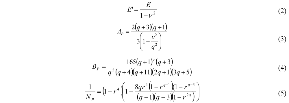
2.1.1. Diaphragm Deflection Theory</title>
          <p>The diaphragm and valve plate are the moving components of the valve, and their position determines the flow rate through the valve and the valve state (open or closed). For the current device, an etched back p++ silicon layer was chosen as the diaphragm structural material due to its robustness and proven performance [<xref ref-type="bibr" rid="B10-micromachines-03-00379">10</xref>]. The diaphragm was corrugated in order to reduce its spring constant. The equation governing the deflection of bossed corrugated diaphragms was estimated in [<xref ref-type="bibr" rid="B15-micromachines-03-00379">15</xref>,<xref ref-type="bibr" rid="B16-micromachines-03-00379">16</xref>] and an approximation is given in Equation (1).</p>
          <p><inline-graphic xmlns:xlink="http://www.w3.org/1999/xlink" xlink:href="micromachines-03-00379-i001.tif"/></p>
          <p>In this equation, <italic>P</italic> is the pressure, <italic>R</italic> is the diaphragm radius, <italic>y</italic> is the deflection of the valve plate and h is the thickness of the diaphragm. <italic>E</italic>’, <italic>A<sub>P</sub></italic>, <italic>B<sub>P</sub></italic>, and <italic>N<sub>P</sub></italic> are defined in the following equations.</p>
          <p><inline-graphic xmlns:xlink="http://www.w3.org/1999/xlink" xlink:href="micromachines-03-00379-i002.tif"/></p>
          <p><italic>E</italic> and <italic>ν</italic> are the Young’s Modulus and Poisson’s Ratio of the diaphragm material and <italic>r</italic> is the ratio of boss radius to diaphragm radius. <italic>q</italic>, the corrugation quality factor and for shallow, sinusoidal profiles is given by Equation (6), where H is the corrugation depth.</p>
          <p><inline-graphic xmlns:xlink="http://www.w3.org/1999/xlink" xlink:href="micromachines-03-00379-i003.tif"/></p>
          <p>In these equations, the initial stress of the diaphragm is ignored, but can be added as a term on the right side of Equation (1) [<xref ref-type="bibr" rid="B17-micromachines-03-00379">17</xref>]. When deflection <italic>versus</italic> pressure is plotted using Equation (1), it is immediately apparent that there is an initial period where a small increase in differential pressure yields a large deflection. For valves with low flow-rate requirements, it would be advantageous to operate in this regime. After the initial period, further increases in deflection require larger increases in differential pressure. </p>
          <p>Equation (1) shows the large impact that the diaphragm thickness (h) has on the diaphragm’s characteristics. By decreasing the thickness from 4.2 to 3 μm, the required pressure to achieve a 38 μm deflection is reduced from 209 kPa to 103 kPa. Thus, the choice of diaphragm thickness impacts the rest of the valve design. In the end, the equations above and previous experience were utilized to choose an outer radius of 750 μm, boss radius of 475 μm, and 2 μm corrugation depth. After fabrication was completed (see <xref ref-type="sec" rid="sec2dot2-micromachines-03-00379">Section 2.2</xref>), diaphragm thickness was measured at 4.2 μm.</p>
        </sec>
        <sec>
          <title>2.1.2. Thermopneumatic Theory</title>
          <p>At the heart of the microvalve is the thermopneumatic actuator. Using previous experimental data [<xref ref-type="bibr" rid="B10-micromachines-03-00379">10</xref>,<xref ref-type="bibr" rid="B14-micromachines-03-00379">14</xref>], a first order thermal model of the actuation cavity can be derived as shown in <xref ref-type="fig" rid="micromachines-03-00379-f002">Figure 2</xref>. R<sub>L</sub> and C<sub>L</sub> are the thermal resistance and capacitance of the working fluid and R<sub>S</sub> and C<sub>S</sub> are the thermal resistance and capacitance of the silicon and glass substrates. This model makes several assumptions, all of which have been shown valid [<xref ref-type="bibr" rid="B10-micromachines-03-00379">10</xref>,<xref ref-type="bibr" rid="B14-micromachines-03-00379">14</xref>]. First, the model assumes efficient heating: that the heat lost through the support posts of the heater is negligible and that all of the energy is generated in the elevated heater grid. The former can be accomplished by minimizing the cross-sectional area of the heater and the latter through the use of low-resistance electrical interconnects. Second, the model assumes that conduction is the main source for heat loss in the system. Thus, the effects of convection and radiation have been ignored.</p>
          <fig id="micromachines-03-00379-f002" position="anchor">
            <label>Figure 2</label>
            <caption>
              <p>First order thermal circuit for thermopneumatic actuator (<bold>a</bold>) and simulated transient response for the standalone, energized thermopneumatic actuator with a close-up of the first 400 ms (<bold>b</bold>). I represents the power applied to the heater. R<sub>L</sub> and C<sub>L</sub> are the thermal resistance and capacitance from the heater to the surrounding valve body. C<sub>L</sub> is dominated by the capacity of the working fluid. R<sub>L</sub> is dominated by the resistance of the working fluid (liquid) under the heater grid. C<sub>S</sub> and R<sub>S</sub> are the thermal resistance and capacitance of the valve substrate/body surrounding the thermopneumatic chamber. In the simulation, the input power of 250 mW was applied at 0 s and removed at 20 s.</p>
            </caption>
            <graphic xmlns:xlink="http://www.w3.org/1999/xlink" xlink:href="micromachines-03-00379-g002.tif"/>
          </fig>
          <p>The thermal resistances and capacitances in the circuit were calculated using Equations (7) and (8). <italic>L</italic>, <italic>A</italic>, and <italic>V</italic> are the length, area, and volume of the material and are given in the direction of heat transfer. <italic>σ</italic> is the thermal conductivity of the material, <italic>c</italic> is its heat capacity, and <italic>ρ</italic> is its density. </p>
          <p><inline-graphic xmlns:xlink="http://www.w3.org/1999/xlink" xlink:href="micromachines-03-00379-i004.tif"/></p>
          <p>The calculations result in R<sub>L</sub> = 158 × 10<sup>−3</sup> K/mW, C<sub>L</sub> = 5.7 × 10<sup>−4</sup> J/K, R<sub>S</sub> = 71 × 10<sup>−3</sup> K/mW, and C<sub>S</sub> = 0.16 J/K. R<sub>L</sub>, the thermal resistance from the heater grid to the valve body, was calculated assuming that the working fluid fills 20% of the actuation cavity; it is dominated by losses through the working fluid directly below the heater grid. R<sub>S</sub> includes the resistance of the substrate in addition to the resistance of the PCB board that the device was mounted on for testing.</p>
          <p>The circuit in <xref ref-type="fig" rid="micromachines-03-00379-f002">Figure 2</xref> was simulated in HSpice assuming a 50 µm recess below the heater and an input power of 250 mW. The power was applied at 0 s and removed at 20 s. The simulation results are shown in <xref ref-type="fig" rid="micromachines-03-00379-f002">Figure 2</xref> and display two distinct regimes of heating. In the first, the working fluid temperature increases rapidly with little required energy. In the second, much more energy is consumed as the rest of the valve slowly heats up. Thus, to fully maximize the performance and minimize the energy requirements of the valve, the device should be designed such that the temperature rise in the first heating regime is sufficient to close the valve. Ideally, the valve will then be latched (after the first heating regime), and operation in the second regime will be completely avoided, saving energy and improving the closing speed. In addition, if the second heating regime is avoided, less thermal energy will need to be dissipated from the device in order to cool down the fluid and open the valve again. Thus, the hybrid actuator has the potential to greatly increase the speed of the device during both transitions (open-to-closed and closed-to-open). The capacitance of the electrostatic latch is used to monitor the valve seat position to determine the state of the valve and when to latch in order to minimize energy consumption. As shown in <xref ref-type="fig" rid="micromachines-03-00379-f002">Figure 2</xref>, the simple thermal model predicts a temperature rise of 39 K in 400 ms while consuming 100 mJ of energy for a 50 μm recess under the heater. If the recess under the heater is increased to 100 μm, the same temperature rise can be achieved in 230 ms according to the model.</p>
          <p>This valve uses a rectangular design for the heater grid, in contrast to the diamond-shaped grids in [<xref ref-type="bibr" rid="B12-micromachines-03-00379">12</xref>] and [<xref ref-type="bibr" rid="B14-micromachines-03-00379">14</xref>], which were used to promote wetting by the fluid and heat transfer to the fluid. The diamond-shaped grids were designed for low fill fractions of the working fluid. In this work, larger fill fractions are assumed and a rectangular grid was chosen to increase the resistance and efficiency of the heater, increase the heat transfer area to the fluid, and increase the structural integrity of the heater. In [<xref ref-type="bibr" rid="B12-micromachines-03-00379">12</xref>], additional anchors were used throughout the grid to improve its mechanical stability; however, this reduced its thermal isolation. The current grid does not use additional anchors.</p>
          <p>Utilizing the temperature of the cavity as predicted using the model above, the pressure generated by the thermopneumatic actuator can be calculated using the Clausius-Clapeyron relation [<xref ref-type="bibr" rid="B10-micromachines-03-00379">10</xref>], which provides the pressure of a working fluid in a closed cavity as a function of temperature.</p>
          <p><inline-graphic xmlns:xlink="http://www.w3.org/1999/xlink" xlink:href="micromachines-03-00379-i005.tif"/></p>
          <p>In Equation (9), <italic>p<sub>g</sub></italic> and <italic>T</italic><sub>lg</sub> are the pressure and temperature (in K) of the working fluid and gas in the cavity, <italic>p<sub>g,o</sub></italic> and <italic>T</italic><sub>lg,<italic>o</italic></sub> are the initial pressure and temperature of the working fluid and gas in the cavity, <italic>M</italic> is its molecular mass of the working fluid, Δ<italic>h</italic><sub>lg</sub> is the heat of vaporization, and <italic>R<sub>g</sub></italic> is the universal gas constant. The pressure of the residual air in the cavity must also be taken into account and can be calculated using the ideal gas law and the law of partial pressures. In general, the lower the boiling point of the working fluid, the larger the pressure it generates for a given temperature. For the current work, pentane was chosen as the working fluid for its low boiling point (36 °C at 101.325 kPa), ease of handling, and availability. The simple thermal model and Equation (9) were used to estimate the pressure response of the system <italic>versus</italic> time as shown in <xref ref-type="fig" rid="micromachines-03-00379-f002">Figure 2</xref>, which predicts a pressure rise of 173 kPa in 400 ms and 280 kPa in 20 s.</p>
        </sec>
        <sec>
          <title>2.1.3. Flow Theory</title>
          <p>Because the valve is being developed as part of a μGC system, it is critical that it have a low pressure drop in order to reduce its impact on the rest of the system. That is, if the valve has a large fluidic resistance (small fluidic conductance) when open, it will reduce the flow rate during all stages of operation and negatively impact system performance. Thus, it is advantageous to maximize the flow conductance (flow rate for a given pressure) of the valve. The flow rate can be calculated from standard fluid flow theory as in Equation (10).</p>
          <p><inline-graphic xmlns:xlink="http://www.w3.org/1999/xlink" xlink:href="micromachines-03-00379-i006.tif"/></p>
          <p>In this equation, <italic>P<sub>DIFF</sub></italic> is the differential pressure across the flow channel, <italic>R<sub>FLUID</sub></italic> is the fluidic resistance of the channel, <italic>η</italic> is the viscosity of the fluid, <italic>L</italic> is the length of the channel, <italic>W</italic> is the channel width and <italic>h</italic> is the height of the channel. This equation is valid for two parallel plates and incompressible flow. In the current device, a channel width of 2.3 mm was chosen to accommodate the width of the valve membrane (1.5 mm) and a length of 3 mm was chosen for ease of testing. A channel height (also the required valve plate travel distance) of 38 μm was chosen as a tradeoff between fabrication considerations, the pressure required to close the valve, and the desire to maximize the flow rate. Assuming a viscosity of 1.8 × 10<sup>−5</sup> Ns/m<sup>2</sup> for air, the model predicts a flow rate of 8 sccm for a differential pressure of 670 Pa.</p>
        </sec>
        <sec>
          <title>
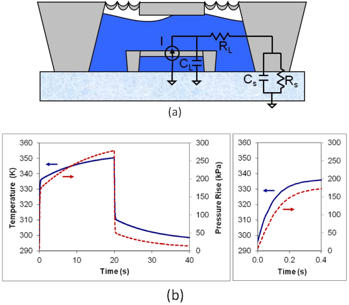
2.1.4. Position Sensor Theory</title>
          <p>The position sensor in the valve is capacitive and is based on the variation of capacitance with distance. For the current valve, the total capacitance is determined by three separate capacitances: the capacitance of the air between the valve plates, the capacitance of the insulating dielectric on the top electrode, and parasitic capacitance; only the capacitance of the air changes (<xref ref-type="fig" rid="micromachines-03-00379-f001">Figure 1</xref>). The total capacitance of the pressure sensor can be written as the combination of the three capacitances.</p>
          <p><inline-graphic xmlns:xlink="http://www.w3.org/1999/xlink" xlink:href="micromachines-03-00379-i007.tif"/></p>
          <p><italic>C<sub>T</sub></italic> is the total capacitance, <italic>C<sub>AIR</sub></italic> and <italic>C<sub>INS</sub></italic> are the capacitance of the air and insulator and are calculated using the equation for a parallel plate capacitor (C = εA/d), and <italic>C<sub>P</sub></italic> is the parasitic capacitance. In the capacitance equation, ε is the permittivity of the dielectric material, A is the area of the electrodes and d is the distance between the electrodes. A capacitor area of 5.2 × 10<sup>−7</sup> m<sup>2</sup>, insulator and air relative permittivities of 3.9 and 1.0, respectively, an insulator thickness of 2.3 μm, an initial air gap of 38 μm, and a parasitic capacitance of 2.7 pF were assumed in the calculations. In addition, it was assumed that the capacitance reached a maximum and no longer increased when the valve plate was predicted to be fully actuated.</p>
        </sec>
        <sec>
          <title>2.1.5. Electrostatic Latch Theory
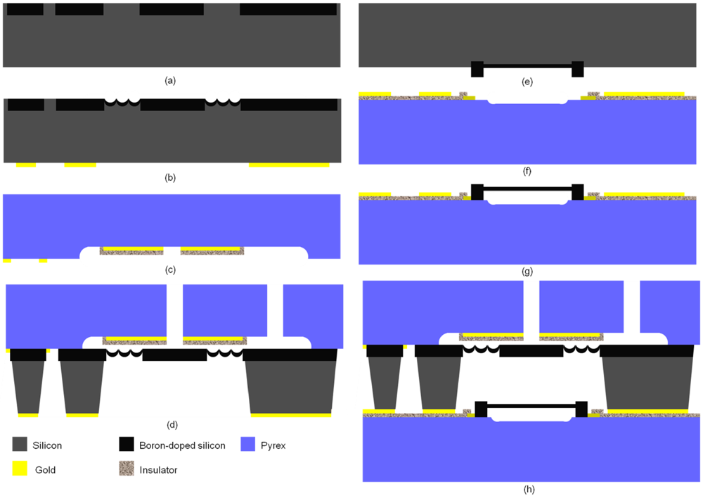
</title>
          <p>The spring constant of the diaphragm has a large impact on the voltage required to completely latch the valve in the closed position. The force of an electrostatic actuator is given by Equation (12).</p>
          <p><inline-graphic xmlns:xlink="http://www.w3.org/1999/xlink" xlink:href="micromachines-03-00379-i008.tif"/></p>
          <p>In this equation, <italic>A<sub>E</sub></italic> is the area of the electrostatic actuator, <italic>V</italic> is the electrostatic voltage, <italic>ε</italic> is the permittivity of the dielectric, and <italic>t</italic> is the dielectric thickness. In order for the valve to completely latch, the electrostatic actuator must generate a force that is equal to or greater than the force required to close the valve. An estimate of this force may be determined by multiplying the pressure of the pneumatic actuator by the effective area of the diaphragm. Once this force is known, Equation (12) may be solved for the required latching voltage. The electrostatic electrode area, relative permittivity of the dielectric, and dielectric thickness were assumed to be 5.2 × 10<sup>−7</sup> m<sup>2</sup>, 3.9 and 2.3 μm, respectively. For a diaphragm thickness of 4.2 µm, a pressure of 209 kPa is required for a valve plate deflection of 38 μm. Rearranging Equation (12) and substituting in the numbers above results in an estimated minimum latching voltage of 250 V. This relatively high could be reduced significantly by decreasing the diaphragm thickness, increasing its size, or increasing the electrode area.</p>
        </sec>
      </sec>
      <sec id="sec2dot2-micromachines-03-00379">
        <title>2.2. Fabrication</title>
        <p>The fabrication of the valve, shown in <xref ref-type="fig" rid="micromachines-03-00379-f003">Figure 3</xref>, begins with the formation of a deep boron etch-stop (~10 μm) to define the valve body (<xref ref-type="fig" rid="micromachines-03-00379-f003">Figure 3</xref>(a)). Next, a shallow isotropic etch is performed to define the diaphragm corrugations and to recess the wafer areas that will not be anodically bonded later (<xref ref-type="fig" rid="micromachines-03-00379-f003">Figure 3</xref>(b)). A shallow boron diffusion (~4 μm) then defines the valve diaphragm, and Cr/Au metallization is patterned on the front of the wafer to form a substrate electrical contact during the anodic bond (<xref ref-type="fig" rid="micromachines-03-00379-f003">Figure 3</xref>(b)). Next, Cr/Au metallization is patterned on the bottom of the wafer (<xref ref-type="fig" rid="micromachines-03-00379-f003">Figure 3</xref>(b)). This later will later serve to form a Si/Au eutectic bond with the heater wafer. Separately, a 38 μm recess is wet etched using HF in a Pyrex wafer to form the fluidic flow channel and accommodate valve plate movement (<xref ref-type="fig" rid="micromachines-03-00379-f003">Figure 3</xref>(c)). Next, a Ti/Pt/Au layer is deposited and patterned to form the top electrode of the electrostatic latch and position sensor; the bottom electrode is the substrate of the silicon wafer (<xref ref-type="fig" rid="micromachines-03-00379-f003">Figure 3</xref>(c)). Then, a PECVD oxynitride film is deposited and patterned to insulate the top electrode (<xref ref-type="fig" rid="micromachines-03-00379-f003">Figure 3</xref>(c)). This insulator only exists in the recessed area and thus does not affect the anodic bond. Fluidic ports are wet etched in the glass wafer using a NaOH electrochemical etch, and the two wafers are anodically bonded together (<xref ref-type="fig" rid="micromachines-03-00379-f003">Figure 3</xref>(d)). Finally, an ethylene diamine pyrocatechol (EDP) etch is done to release the valve seat and diaphragm and separate individual valve bodies (<xref ref-type="fig" rid="micromachines-03-00379-f003">Figure 3</xref>(d)). A released valve body wafer is shown in <xref ref-type="fig" rid="micromachines-03-00379-f004">Figure 4</xref>. The EDP etch forms pillars that will later serve as lead transfers for electrical signals between the top and bottom wafer.</p>
        <fig id="micromachines-03-00379-f003" position="anchor">
          <label>Figure 3</label>
          <caption>
            <p>The fabrication process for the microvalve. The valve body (<bold>a</bold>–<bold>d</bold>) and heater (<bold>e</bold>–<bold>g</bold>) are formed using a silicon-on-glass process and processed in parallel. A deep boron diffusion is utilized to define the valve body and plate (<bold>a</bold>) as well as the heater anchors (<bold>e</bold>). The glass is recessed to form fluid channels (<bold>c</bold>) and improve heater isolation (<bold>f</bold>). A metallization step is performed for electrical contact to the valve components (<bold>b</bold>,<bold>c</bold>,<bold>f</bold>). An anodic bond seals the valve body to the top glass wafer (<bold>d</bold>) and the heater to the bottom glass wafer (<bold>g</bold>) and the undoped silicon is removed in an EDP etch (<bold>d </bold>and <bold>g</bold>). The valve body wafer and heater wafer are then bonded together using a Au-Si eutectic or epoxy bond (<bold>h</bold>). </p>
          </caption>
          <graphic xmlns:xlink="http://www.w3.org/1999/xlink" xlink:href="micromachines-03-00379-g003.tif"/>
        </fig>
       
        <p>The elevated heater is formed in an analogous manner to the process described above, and, in fact, the two wafers can be processed in parallel. The fabrication begins with a short isotropic etch (to elevate the heater) on the silicon wafer, following with patterned deep and shallow boron diffusions and contact metallization (<xref ref-type="fig" rid="micromachines-03-00379-f003">Figure 3</xref>(e)). On a separate Pyrex wafer, a Ti/Pt/Au metal layer is deposited and patterned to form the electrical leads, a PECVD oxynitride is deposited and patterned to insulated the leads, a Ti/Pt/Au layer is plated to form a bond ring (for the final Au/Si eutectic bond [<xref ref-type="bibr" rid="B18-micromachines-03-00379">18</xref>]), and fluidic ports are etched through the glass wafer (<xref ref-type="fig" rid="micromachines-03-00379-f003">Figure 3</xref>(f)). These ports are later used to fill the device with the working fluid. An electrostatic bond is then performed, and an EDP etch is utilized to release the heater (<xref ref-type="fig" rid="micromachines-03-00379-f003">Figure 3</xref>(g)). A finished heater is shown in <xref ref-type="fig" rid="micromachines-03-00379-f004">Figure 4</xref> (lower left). Finally, the valve body wafer and the heater wafer are bonded together utilizing a Si/Au eutectic bond, and then diced to separate the individual die (<xref ref-type="fig" rid="micromachines-03-00379-f003">Figure 3</xref>(h)). After fabrication, the die are injected with the working fluid (pentane) and sealed with epoxy. Capillary tubing was then epoxied into the fluidic ports of the valve for testing. In some of the devices, capillary tubing was attached to the actuation chamber using epoxy for perform pneumatic testing.</p>
         <fig id="micromachines-03-00379-f004" position="anchor">
          <label>Figure 4</label>
          <caption>
            <p>Pictures of the top (<bold>upper left</bold>) and bottom (<bold>upper right</bold>) of the finished valve body wafer, a released, suspended heater grid (<bold>bottom left</bold>) and completed device on a penny (<bold>bottom right</bold>). The fluidic input and output are visible in the top left image. The valve diaphragm, plate, and actuation are visible in the upper right picture. The improved isolation (due to the glass recess) of the heater is visible in the bottom left.</p>
          </caption>
          <graphic xmlns:xlink="http://www.w3.org/1999/xlink" xlink:href="micromachines-03-00379-g004.tif"/>
        </fig>
      </sec>
      <sec>
        <title>2.3. Experimental Setup</title>
        <p>Inspection and measurements were performed using both standard and scanning electron microscopy (SEM). Resistance values were measured using a probe station and Keithley 2000 Digital Mutlimeter (DMM) in a four point probe configuration. Capacitance values were measured using a HP 4284A LCR meter. Unless otherwise stated, pressures were fixed with a standard 60 psi (414 kPa) pressure regulator and verified using two MKS 740 pressure sensors at the input and output of the device under test. Flow rates were measured using an MKS 170 10 sccm flow meter. Nitrogen was used as the test gas in all cases. Valve leak rates (&lt;0.01 sccm) were determined by measuring the change in pressure over time for a small fixed volume at the outlet of the closed valve as described in detail in [<xref ref-type="bibr" rid="B10-micromachines-03-00379">10</xref>]. The pressure/flow characteristics of the test setup were measured before inserting the valve for testing. With this method, the values of the test setup could be subtracted from those of the valve and test setup to determine the values for the valve alone. Transient measurements were captured via a GPIB interface and LabView<sup>®</sup>.</p>
        <sec>
          <title>2.3.1. Open Flow Characterization</title>
          <p>Pressure was fixed using a DH Instrument PPC2 programmable pressure controller. Pressure and flow were measured using two pressure sensors and a flow sensor, described above.</p>
        </sec>
        <sec>
          <title>2.3.2. Position Sensor Characterization</title>
          <p>The thermopneumatic actuation chamber was connected to a DH Instrument PPC2 programmable pressure controller. The valve flow input and output were open to ambient. The capacitance of the sensor was measured using an LCR meter as pressure was varied using the PPC2 controller. </p>
        </sec>
        <sec id="sec2dot3dot3-micromachines-03-00379">
          <title>2.3.3. Pneumatic Switching Characterization</title>
          <p>The thermopneumatic actuation chamber was connected to the PPC2 pressure controller and flow rate through the valve was measured as a function of actuation pressure, yielding the actuation pressure required to close the valve at various initial flow rates.</p>
          <p>Pneumatic testing was also utilized to determine the base switching capabilities of the valve and the time constant of the test setup. A custom pressure controller containing a pressure regulator and high speed solenoid valve was utilized to rapidly switch (&lt;50 ms) between ambient and a set pressure. This custom pressure controller was connected to the thermopneumatic actuation chamber. Flow through the valve was set to a start value and flow and pressure were measured as a function of time.</p>
          <p>Due to the nature of the test setup, the pressure across the flow path in the valve varied as a function of the valve state. That is, when the valve was open, the fluidic resistance of the valve was small compared to that of the tubing in the test setup. This caused the pressure difference across the valve to be small when open. However, when the valve was closed, the fluidic resistance of the valve was much greater than that of the test setup causing the differential pressure across the flow path of the valve to be large.</p>
        </sec>
        <sec id="sec2dot3dot4-micromachines-03-00379">
          <title>2.3.4. Thermopneumatic Characterization</title>
          <p>The thermopneumatic actuator was tested after filling devices with pentane and sealing them with Loctite<sup>®</sup> 1C™ Hysol<sup>®</sup> epoxy. After drying, the device was inserted into the test setup and an initial flow through the device was fixed. Power was then applied to the heater in the actuation chamber using a Keithley 2400 Source Measure Unit (SMU). Flow and pressure (across the input and output) were measured as a function of time.</p>
        </sec>
        <sec>
          <title>2.3.5. Electrostatic Latch Testing</title>
          <p>First, the open flow rate of the valve was set to 0.06 sccm and then the valve was pneumatically actuated with a pressure of 270 kPa. This pressure was chosen as it was sufficient to close the valve with a leak rate less than 5 × 10<sup>−3</sup> sccm in previous tests. Then, a voltage was applied to the electrostatic latch with a HP 6209B power supply and the valve leak rate was measured as described above.</p>
          <p>A second test was performed to determine if the electrostatic latch could be utilized to reduce the required pressure supplied by the pneumatic or thermopneumatic actuator, thereby reducing energy requirements. For this test, the valve was pneumatically actuated with a pressure of 270 kPa and a valve “initial leak rate” was measured. The electrostatic latch was then activated at 140 V and then the pneumatic pressure was then decreased until the leak rate through the valve increased above the initial leak rate. </p>
        </sec>
      </sec>
    </sec>
    <sec sec-type="results">
      <title>3. Results and Discussion</title>
      <sec>
        <title>
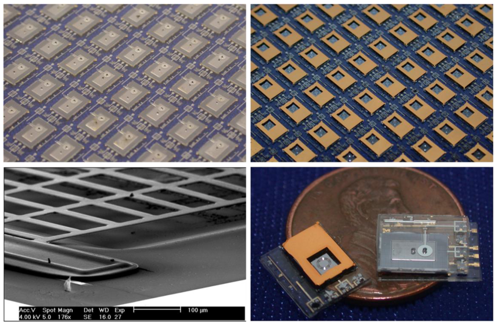
3.1. Microscopy and Resistance Results</title>
        <p>From measurements performed during Scanning Electron Microscopy (SEM), the deep boron diffusion layer was 12 μm thick, the shallow boron layer that forms the diaphragm was 4.2 μm thick, and the initial valve gap distance (or travel distance) was 38 μm.</p>
        <p>From resistance measurements, the suspended, p++ heater resistance was found to be between 7 and 10 Ω, depending on the device. This low resistance is due to the high conductivity of p++ silicon and the relatively large cross-section of each heater beam (32 × 4.2 μm). This equates to a resistance of about 56 Ω for each of the 8, 1.7 mm-long beams in the heater. Next, the resistance of the gold interconnects was measured to be about 13 Ω giving a total heater and lead resistance of about 20 Ω. This parasitic resistance is undesirable in that heat generated in the high resistance leads is not applied directly to the working fluid and instead serves to increase the temperature of the valve substrate. The interconnects were inspected closely under an optical microscope and SEM to determine the cause. Near the point where the gold leads meet the p++ silicon heater, the gold is discolored and has a higher resistance than the rest of the lead. It is believed that during anodic bonding, silicon diffuses into the gold leads forming a eutectic and increasing its resistance. </p>
      </sec>
      <sec>
        <title>3.2. Open Flow Results</title>
        <p>The measured and theoretical open flow rate of the valve at various pressures is shown in <xref ref-type="fig" rid="micromachines-03-00379-f005">Figure 5</xref>(a). The valve had an open flow rate of 8 sccm at 600 Pa corresponding to a fluidic conductance of 2.2 × 10<sup>−4</sup> cm<sup>3</sup>s<sup>−1</sup>Pa<sup>−1</sup>. </p>
        <fig id="micromachines-03-00379-f005" position="anchor">
          <label>Figure 5</label>
          <caption>
            <p>Measured results for the microvalve; (<bold>a</bold>) Measured and theoretical open flow rate. (<bold>b</bold>) Measured and theoretical response of the position sensor as a function of pressure applied to the actuation cavity. The theoretical response was calculated using Equations (1) and (11) to determine deflection and capacitance. The calculation assumes that capacitance stops increasing once the valve plate makes contact with the valve seat. (<bold>c</bold>) Measured results for the pneumatic switching of 2 sccm. The flow changes more slowly than the sensor capacitance due to the fluidic time constant of the test setup. (<bold>d</bold>) Measured thermopneumatic transient response with 90 mW applied to the heater. Although slow, the valve closes at this power level. Flow sensor resolution in the plot is limited to 0.01 sccm. (<bold>e</bold>) Measured thermopneumatic transient response with 250 mW applied to the heater and (<bold>f</bold>) a close-up of the transition.</p>
          </caption>
          <graphic xmlns:xlink="http://www.w3.org/1999/xlink" xlink:href="micromachines-03-00379-g005.tif"/>
        </fig>
      </sec>
      <sec>
        <title>
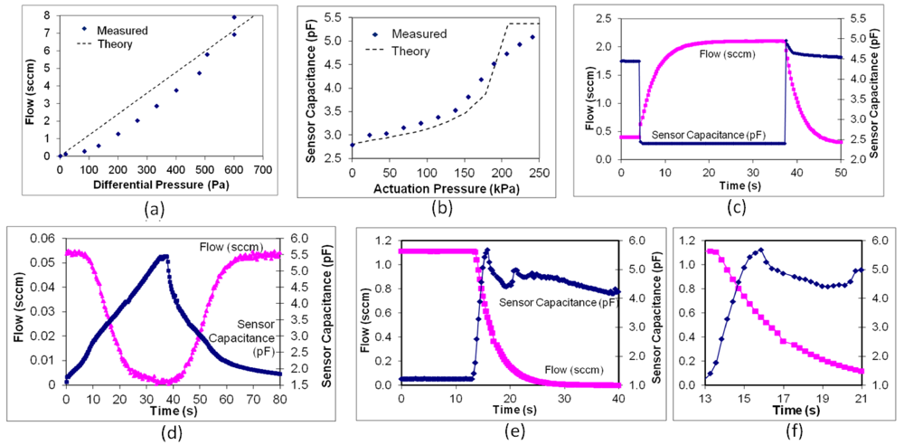
3.3. Position Sensor Results</title>
        <p>The capacitance of the sensor increased as the pneumatic pressure applied to the actuation cavity increased as shown in <xref ref-type="fig" rid="micromachines-03-00379-f005">Figure 5</xref>(b). Overall, the capacitive position sensor had a sensitivity of 9.8 fF/kPa over its operating range.</p>
      </sec>
      <sec>
        <title>3.4. Pneumatic Switching Results</title>
        <p>In pneumatic testing, the valve began to close (flow rate through the valve decreased) at actuation pressures above 170 kPa. The actual closing pressure depends on the open flow rate and the required leak rate for a given application. Higher closing pressures are required for larger open flow rates (larger differential pressures) and smaller leak rates.</p>
        <p>Results from pneumatic switching tests are shown in <xref ref-type="fig" rid="micromachines-03-00379-f005">Figure 5</xref>(b) for an initial open flow rate of 2 sccm and a pneumatic actuation pressure of 200 kPa. Due to the nature of the test setup, the pressure across the valve flow path increases from 280 Pa when open to 40 kPa when closed (see <xref ref-type="sec" rid="sec2dot3dot3-micromachines-03-00379">Section 2.3.3</xref>). Although the leak rate of the valve was 0.3 sccm in this test, the leak rate can approach 0.001 sccm for a larger actuation pressure. The time constant of the test setup can also be determined from <xref ref-type="fig" rid="micromachines-03-00379-f005">Figure 5</xref>(b). When the pneumatic pressure is switched closing the valve, the capacitance increases very rapidly (&lt;250 ms) from 2.5 pF to 5 pF. The much slower switching time (90%–10% of 6.7 s) of the flow reflects the fluidic time constant of the test setup and not the valve itself.</p>
      </sec>
      <sec>
        <title>3.5. Thermopneumatic Switching Results</title>
        <p>After filling the devices with pentane, power was applied to the heater in the actuator cavity and the flow and capacitance of the position sensor were measured. At 90 mW applied to the heater (260 mW total applied to the elevated p++ silicon heater and gold leads) and an open flow rate of 0.054 sccm, the combined valve and test setup have a flow rate switching time (90%–10%) of 13.6 s. Subtracting out the time constant of the test setup, this gives a switching time of 6.9 s. Due to the nature of the test setup, when the valve is open, the differential pressure across it is 70 Pa. When the valve is closed, the pressure across it is 1.3 kPa. The leak rate for the closed valve is 1.3 × 10<sup>−3</sup> sccm. </p>
        <p>At an open flow rate of 6.74 sccm, when 200 mW is applied to the heater (570 mW applied to the heater and leads), the valve flow rate switches in 1.1 s (90%–10%), with a leak rate of 2.2 × 10<sup>−3</sup> sccm. Pressure across the valve flow path was 530 Pa when open and 115 kPa when closed. This results in an open-to-closed fluidic conductance ratio of nearly one million. </p>
        <p>Finally, with 250 mW applied to the heater (710 mW applied to the heater and leads), the valve switches from an initial flow rate of 1.1 sccm in 430 ms (90%–10%, after subtracting out the time constant of the test setup) as shown in <xref ref-type="fig" rid="micromachines-03-00379-f005">Figure 5</xref>(c). Pressure across the valve flow path was 190 Pa when open and 20 kPa when closed. The leak rate with 250 mW applied to the heater was to 1.4 × 10<sup>−3</sup> sccm. </p>
        <p>Although a high power is required to close the valve quickly, a power of 90 mW applied to the elevated heater will hold the valve closed. Also, a lower hold power may be used if a higher leak rate can be tolerated in the application.</p>
      </sec>
      <sec>
        <title>3.6. Electrostatic Latch Results</title>
        <p>In testing of the electrostatic latch, as the latch voltage increased, the leak rate decreased. By applying up to 140 V, the leak rate of the closed valve could be reduced by almost a factor of 2 (from 5.5 × 10<sup>−3</sup> to 3 × 10<sup>−3</sup> sccm). Breakdown of the insulator in the electrostatic latch occurred for voltages greater than 140 V prohibiting testing at higher voltages. In the second electrostatic latch test (see <xref ref-type="sec" rid="sec2dot3dot4-micromachines-03-00379">Section 2.3.4</xref>), a voltage of 140 V applied to the electrostatic latch enabled the applied pneumatic pressure to decrease from 270 kPa to 190 kPa, or a decrease of 30%. However, the latch could not hold the valve closed by itself.</p>
      </sec>
      <sec>
        <title>3.7. Discussion</title>
        <p>Relatively simple modifications to the present structure could improve the performance of the device substantially. First, the diaphragm should be thinned from 4.2 μm to 3 μm in order to reduce the spring constant of the diaphragm, thereby reducing the pressure required to close the device (from 270 to 130 kPa) and reducing the required electrostatic hold voltage. Next, all of the glass underneath the heater should be removed to maximize its thermal isolation. Additionally, the gold leads should be redesigned so that their resistance is negligible to the heater resistance after completion. This will eliminate inefficient heating of the valve substrate by the gold leads. Finally, the quality of the electrostatic latch insulator should be improved so that it can sustain applied voltages greater than 140 V. With these improvements, a valve with the same flow and leak properties as before but capable of closing in 140 ms at 250 mW, requiring a hold power of 20 mW without the electrostatic latch, and negligible hold power with an electrostatic voltage of 175 V. Small increases in diaphragm diameter and increasing the depth and number of the diaphragm corrugations would also lead to improved performance as would increasing the electrostatic contact area.</p>
      </sec>
    </sec>
    <sec sec-type="conclusions">
      <title>4. Conclusions</title>
      <p>This paper has presented a microvalve that combines thermopneumatic actuation for large force with electrostatic latching for low hold power. A built-in capacitive sensor allows closed-loop control of valve plate position. Although complete electrostatic latching was not achieved, the paper provides theory and guidelines to understand the performance limits to achieve an optimized device. It further demonstrates that hybrid actuators, when designed appropriately, may be utilized to eliminate the drawbacks of each stand-alone technology.</p>
    </sec>

  </body>
  <back>
    <ack>
    <title>Acknowledgments</title>
      <p>The authors would like to thank Jay Mitchell for his advice and assistance with the design of the Au-Si eutectic bonding technology. This work was supported by the Engineering Research Centers Program of the National Science Foundation under Award Number EEC-9986866. </p>
    </ack>
    <ref-list>
      <title>References</title>
      <ref id="B1-micromachines-03-00379">
        <label>1.</label>
        <citation citation-type="confproc">
          <person-group person-group-type="author">
            <name>
              <surname>Shoji</surname>
              <given-names>S.</given-names>
            </name>
            <name>
              <surname>Esashi</surname>
              <given-names>M.</given-names>
            </name>
          </person-group>
          <article-title>Micro flow devices</article-title>
          <source>Proceedings of the 5th International Symposium on Micro Machine and Human Science</source>
          <conf-loc>Nagoya, Japan</conf-loc>
          <conf-date>October 1994</conf-date>
          <fpage>89</fpage>
          <lpage>95</lpage>
        </citation>
      </ref>
      <ref id="B2-micromachines-03-00379">
        <label>2.</label>
        <citation citation-type="journal">
          <person-group person-group-type="author">
            <name>
              <surname>Oh</surname>
              <given-names>K.W.</given-names>
            </name>
            <name>
              <surname>Ahn</surname>
              <given-names>C.H.</given-names>
            </name>
          </person-group>
          <article-title>A review of microvalves</article-title>
          <source>J. Micromech. Microeng.</source>
          <year>2006</year>
          <volume>16</volume>
          <fpage>R13</fpage>
          <lpage>R39</lpage>
        <pub-id pub-id-type="doi">10.1088/0960-1317/16/5/R01</pub-id></citation>
      </ref>
      <ref id="B3-micromachines-03-00379">
        <label>3.</label>
        <citation citation-type="journal">
          <person-group person-group-type="author">
            <name>
              <surname>Bosch</surname>
              <given-names>D.</given-names>
            </name>
            <name>
              <surname>Heimhofer</surname>
              <given-names>B.</given-names>
            </name>
            <name>
              <surname>Muck</surname>
              <given-names>G.</given-names>
            </name>
            <name>
              <surname>Seidel</surname>
              <given-names>H.</given-names>
            </name>
            <name>
              <surname>Thumser</surname>
              <given-names>U.</given-names>
            </name>
            <name>
              <surname>Welser</surname>
              <given-names>W.</given-names>
            </name>
          </person-group>
          <article-title>A silicon microvalve with combined electromagnetic/electrostatic actuation</article-title>
          <source>Sens. Actuat. A</source>
          <year>1993</year>
          <volume>37–38</volume>
          <fpage>684</fpage>
          <lpage>692</lpage>
          <pub-id pub-id-type="doi">10.1016/0924-4247(93)80116-X</pub-id>
        </citation>
      </ref>
      <ref id="B4-micromachines-03-00379">
        <label>4.</label>
        <citation citation-type="confproc">
          <person-group person-group-type="author">
            <name>
              <surname>Wagner</surname>
              <given-names>B.</given-names>
            </name>
            <name>
              <surname>Quenzer</surname>
              <given-names>M.</given-names>
            </name>
            <name>
              <surname>Hoerschelmann</surname>
              <given-names>S.</given-names>
            </name>
            <name>
              <surname>Lisec</surname>
              <given-names>T.</given-names>
            </name>
            <name>
              <surname>Juerss</surname>
              <given-names>M.</given-names>
            </name>
          </person-group>
          <article-title>Bistable microvalve with pneumatically coupled membranes</article-title>
          <source>Proceedings of the 9th Annual International Workshop on Micro Electro Mechanical Systems (MEMS)</source>
          <conf-loc>San Diego, CA, USA</conf-loc>
          <conf-date>February 1996</conf-date>
          <fpage>384</fpage>
          <lpage>388</lpage>
        </citation>
      </ref>
      <ref id="B5-micromachines-03-00379">
        <label>5.</label>
        <citation citation-type="journal">
          <person-group person-group-type="author">
            <name>
              <surname>Capanu</surname>
              <given-names>J.G.</given-names>
            </name>
            <name>
              <surname>Boyd</surname>
              <given-names>J.G.</given-names>
              <suffix>IV.</suffix>
            </name>
            <name>
              <surname>Hesketh</surname>
              <given-names>P.J.</given-names>
            </name>
          </person-group>
          <article-title>Design, fabrication, and testing of a bistable electromagnetically actuated microvalve</article-title>
          <source>JMEMS</source>
          <year>2000</year>
          <volume>9</volume>
          <fpage>181</fpage>
          <lpage>189</lpage>
        </citation>
      </ref>
      <ref id="B6-micromachines-03-00379">
        <label>6.</label>
        <citation citation-type="confproc">
          <person-group person-group-type="author">
            <name>
              <surname>Frank</surname>
              <given-names>J.A.</given-names>
            </name>
            <name>
              <surname>Pisano</surname>
              <given-names>A.P.</given-names>
            </name>
          </person-group>
          <article-title>A low-power, low-leakage, bi-stable planar electrolysis micro gate valve</article-title>
          <source>Proceedings of the Solid-State Sensor, Actuator and Microsystems Workshop</source>
          <conf-loc>Hilton Head, SC, USA</conf-loc>
          <conf-date>June 2004</conf-date>
          <fpage>156</fpage>
          <lpage>159</lpage>
        </citation>
      </ref>
      <ref id="B7-micromachines-03-00379">
        <label>7.</label>
        <citation citation-type="journal">
          <person-group person-group-type="author">
            <name>
              <surname>Shaikh</surname>
              <given-names>K.A.</given-names>
            </name>
            <name>
              <surname>Li</surname>
              <given-names>S.</given-names>
            </name>
            <name>
              <surname>Liu</surname>
              <given-names>C.</given-names>
            </name>
          </person-group>
          <article-title>Development of a latchable microvalve employing a low-melting-temperature metal alloy</article-title>
          <source>JMEMS</source>
          <year>2008</year>
          <volume>17</volume>
          <fpage>1195</fpage>
          <lpage>1203</lpage>
        </citation>
      </ref>
      <ref id="B8-micromachines-03-00379">
        <label>8.</label>
        <citation citation-type="confproc">
          <person-group person-group-type="author">
            <name>
              <surname>Yang</surname>
              <given-names>E.</given-names>
            </name>
            <name>
              <surname>Lee</surname>
              <given-names>C.</given-names>
            </name>
            <name>
              <surname>Mueller</surname>
              <given-names>J.</given-names>
            </name>
          </person-group>
          <article-title>Normally-Closed, Leak-tight piezoelectric microvalve under ultra-high upstream pressure for integrated micropropulsion</article-title>
          <source>Proceedings of the IEEE 16th Annual Conference on Micro Electro Mechanical Systems</source>
          <conf-loc>Kyoto, Japan</conf-loc>
          <conf-date>19–23 January 2003</conf-date>
          <fpage>80</fpage>
          <lpage>83</lpage>
        </citation>
      </ref>
      <ref id="B9-micromachines-03-00379">
        <label>9.</label>
        <citation citation-type="confproc">
          <person-group person-group-type="author">
            <name>
              <surname>Sihler</surname>
              <given-names>J.</given-names>
            </name>
            <name>
              <surname>Slocum</surname>
              <given-names>A.</given-names>
            </name>
            <name>
              <surname>Lang</surname>
              <given-names>J.</given-names>
            </name>
          </person-group>
          <article-title>An electrostatically actuated low-leakage silicon microvalve</article-title>
          <source>Proceedings of the Solid-State Sensor, Actuator, and Microsystems Workshop</source>
          <conf-loc>Hilton Head, SC, USA</conf-loc>
          <conf-date>2004</conf-date>
          <fpage>282</fpage>
          <lpage>285</lpage>
        </citation>
      </ref>
      <ref id="B10-micromachines-03-00379">
        <label>10.</label>
        <citation citation-type="journal">
          <person-group person-group-type="author">
            <name>
              <surname>Rich</surname>
              <given-names>C.A.</given-names>
            </name>
            <name>
              <surname>Wise</surname>
              <given-names>K.D.</given-names>
            </name>
          </person-group>
          <article-title>A high-flow thermopneumatic microvalve with improved efficiency and integrated state sensing</article-title>
          <source>JMEMS</source>
          <year>2003</year>
          <volume>12</volume>
          <fpage>201</fpage>
          <lpage>208</lpage>
        </citation>
      </ref>
      <ref id="B11-micromachines-03-00379">
        <label>11.</label>
        <citation citation-type="confproc">
          <person-group person-group-type="author">
            <name>
              <surname>Robertson</surname>
              <given-names>J.K.</given-names>
            </name>
            <name>
              <surname>Wise</surname>
              <given-names>K.D.</given-names>
            </name>
          </person-group>
          <article-title>A nested electrostatically-actuated microvalve for an integrated microflow controller</article-title>
          <source>Proceedings of the IEEE Workshop on Micro Electro Mechanical Systems (MEMS)</source>
          <conf-loc>Oiso, Japan</conf-loc>
          <conf-date>January 1994</conf-date>
          <fpage>7</fpage>
          <lpage>12</lpage>
        </citation>
      </ref>
      <ref id="B12-micromachines-03-00379">
        <label>12.</label>
        <citation citation-type="journal">
          <person-group person-group-type="author">
            <name>
              <surname>Bergstrom</surname>
              <given-names>P.L.</given-names>
            </name>
            <name>
              <surname>Li</surname>
              <given-names>J.</given-names>
            </name>
            <name>
              <surname>Liu</surname>
              <given-names>Y.</given-names>
            </name>
            <name>
              <surname>Kaviany</surname>
              <given-names>M.</given-names>
            </name>
            <name>
              <surname>Wise</surname>
              <given-names>K.D.</given-names>
            </name>
          </person-group>
          <article-title>Thermally driven phase-change microactuation</article-title>
          <source>JMEMS</source>
          <year>1995</year>
          <volume>4</volume>
          <fpage>10</fpage>
          <lpage>17</lpage>
        </citation>
      </ref>
      <ref id="B13-micromachines-03-00379">
        <label>13.</label>
        <citation citation-type="confproc">
          <person-group person-group-type="author">
            <name>
              <surname>Henning</surname>
              <given-names>A.K.</given-names>
            </name>
            <name>
              <surname>Fitch</surname>
              <given-names>J.</given-names>
            </name>
            <name>
              <surname>Hopkins</surname>
              <given-names>D.</given-names>
            </name>
            <name>
              <surname>Lilly</surname>
              <given-names>L.</given-names>
            </name>
            <name>
              <surname>Faeth</surname>
              <given-names>R.</given-names>
            </name>
            <name>
              <surname>Falsken</surname>
              <given-names>E.</given-names>
            </name>
            <name>
              <surname>Zdeblick</surname>
              <given-names>M.</given-names>
            </name>
          </person-group>
          <article-title>A thermopneumatically actuated microvalve for liquid expansion and proportional control</article-title>
          <source>Proceedings of the International Conference on Solid State Sensors and Actuators (Transducers)</source>
          <conf-loc>Chicago, IL, USA</conf-loc>
          <conf-date>June 1997</conf-date>
          <volume>2</volume>
          <fpage>825</fpage>
          <lpage>828</lpage>
        </citation>
      </ref>
      <ref id="B14-micromachines-03-00379">
        <label>14.</label>
        <citation citation-type="confproc">
          <person-group person-group-type="author">
            <name>
              <surname>Potkay</surname>
              <given-names>J.A.</given-names>
            </name>
            <name>
              <surname>Wise</surname>
              <given-names>K.D.</given-names>
            </name>
          </person-group>
          <article-title>An electrostatically latching thermopneumatic microvalve with closed-loop position sensing</article-title>
          <source>Proceedings of the IEEE Workshop on Micro Electro Mechanical Systems (MEMS)</source>
          <conf-loc>Miami, FL, USA</conf-loc>
          <conf-date>January 2005</conf-date>
          <fpage>415</fpage>
          <lpage>418</lpage>
        </citation>
      </ref>
      <ref id="B15-micromachines-03-00379">
        <label>15.</label>
        <citation citation-type="journal">
          <person-group person-group-type="author">
            <name>
              <surname>Haringx</surname>
              <given-names>J.A.</given-names>
            </name>
          </person-group>
          <article-title>Design of corrugated diaphragms</article-title>
          <source>ASME Trans.</source>
          <year>1957</year>
          <volume>79</volume>
          <fpage>54</fpage>
          <lpage>65</lpage>
        </citation>
      </ref>
      <ref id="B16-micromachines-03-00379">
        <label>16.</label>
        <citation citation-type="journal">
          <person-group person-group-type="author">
            <name>
              <surname>Renhuai</surname>
              <given-names>L.D.</given-names>
            </name>
          </person-group>
          <article-title>Nonlinear analysis of corrugated annular plates under compound load</article-title>
          <source>Sci. Sin. Ser. A</source>
          <year>1985</year>
          <volume>27</volume>
          <fpage>959</fpage>
        </citation>
      </ref>
      <ref id="B17-micromachines-03-00379">
        <label>17.</label>
        <citation citation-type="journal">
          <person-group person-group-type="author">
            <name>
              <surname>Chau</surname>
              <given-names>H.L.</given-names>
            </name>
            <name>
              <surname>Wise</surname>
              <given-names>K.D.</given-names>
            </name>
          </person-group>
          <article-title>Scaling limits in batch-fabricated silicon pressure sensors</article-title>
          <source>IEEE Trans. Electron Devices</source>
          <year>1987</year>
          <volume>34</volume>
          <fpage>850</fpage>
          <lpage>858</lpage>
        <pub-id pub-id-type="doi">10.1109/T-ED.1987.23006</pub-id></citation>
      </ref>
      <ref id="B18-micromachines-03-00379">
        <label>18.</label>
        <citation citation-type="confproc">
          <person-group person-group-type="author">
            <name>
              <surname>Mitchell</surname>
              <given-names>J.S.</given-names>
            </name>
            <name>
              <surname>Najafi</surname>
              <given-names>K.</given-names>
            </name>
          </person-group>
          <article-title>A detailed study of yield and reliability for vacuum packages fabricated in a wafer-level Au-Si eutectic bonding process</article-title>
          <source>Proceedings of the 15th International Conference on Solid-State Sensors, Actuators and Microsystems (Transducers)</source>
          <conf-loc>Denver, CO, USA</conf-loc>
          <conf-date>June 2009</conf-date>
          <fpage>841</fpage>
          <lpage>844</lpage>
        </citation>
      </ref>
    </ref-list>
  </back>
</article>
