Microvalves and Micropumps for BioMEMS †


Abstract
: This review presents an extensive overview of a large number of microvalve and micropump designs with great variability in performance and operation. The performance of a given design varies greatly depending on the particular assembly procedure and there is no standardized performance test against which all microvalves and micropumps can be compared. We present the designs with a historical perspective and provide insight into their advantages and limitations for biomedical uses.1. Introduction
Microvalves and micropumps form the foundation of many different microfluidic systems. Microvalves control routing, timing, and separation of fluids within a microfluidic device and are crucial for designs with complex functionality. Micropumps, on the other hand, are responsible for generating temporal and volumetric fluid movement on-chip and are used to reduce the amount of external hardware necessary to operate a microfluidic device. These two broad categories are further subdivided into several classifications depending on the operating principles that the designs are based on. Each design inherently possesses a number of strengths and weaknesses which must be considered in choosing an appropriate design for a given biomedical application. Microvalves are discussed first, followed by micropumps, since many micropumps are built as a string of microvalves operated in sequence.
2. Microvalves
Microvalves allow the user to control fluid flow in a microchannel by varying a given macroscopic parameter. The valves can be actuated mechanically [1-4], pneumatically [5-13], electrokinetically [14-17], by phase changes [10,11,18-22], or by introduction of external force [23,24]. Using the method of actuation as the differentiating parameter, five major classes of active microvalves can be identified in the literature: electrokinetic, pneumatic, pinch, phase change, and burst. Electrokinetic valves operate in continuous flow systems, serving as a fluid “router” that uses electroosmotic flow to switch fluids from one channel to another. Pneumatic valves typically rely on a flexible membrane to control the flow pattern in the flow channel. Pinch microvalves [1-3] operate by physically deforming PDMS using mechanical pressure. Phase-change microvalves alternate between different phases of materials such as paraffin [10,11,22], hydrogels [20,21], or aqueous solutions [18] to modulate flow. Lastly, burst microvalves are single-use valves that are opened when a flow resistance is overcome [23-25] or when a sacrificial membrane is disintegrated [26-28].
2.1. Electrokinetic Microvalves
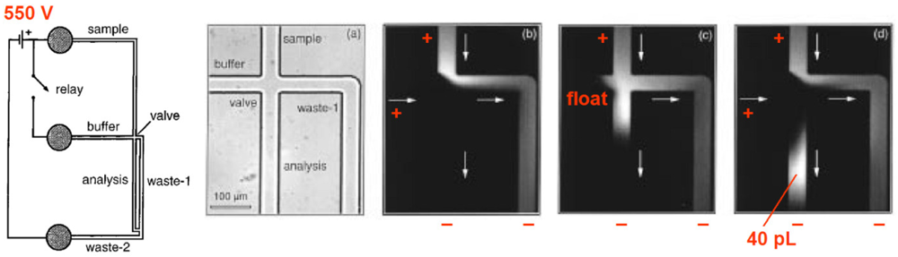
Electrokinetic valving is best described as a “router”, a valving scheme that only works with continuous flow. The earliest implementation of valving in a microfluidic channel is credited to a group led by Andreas Manz, then working at Ciba-Geigy in Basel, Switzerland. In 1993 they reported how electroosmotic flow can be used to quickly switch fluids from one channel to another in a capillary electrophoresis system [29]. Many others rapidly followed, such as J. Michael Ramsey's group at Oak Ridge National Laboratory (Figure 1). In this instance, the sample fluid and the buffer are both attracted by the anode (550 V). When the buffer is disconnected from the cathode, the buffer fluid does not flow and the sample fluid is free to proceed freely. As soon as the buffer is connected to the cathode again, the buffer overtakes the channel, resulting in a small plug whose size is a function of the duration of the voltage pulse and flow rate [16].
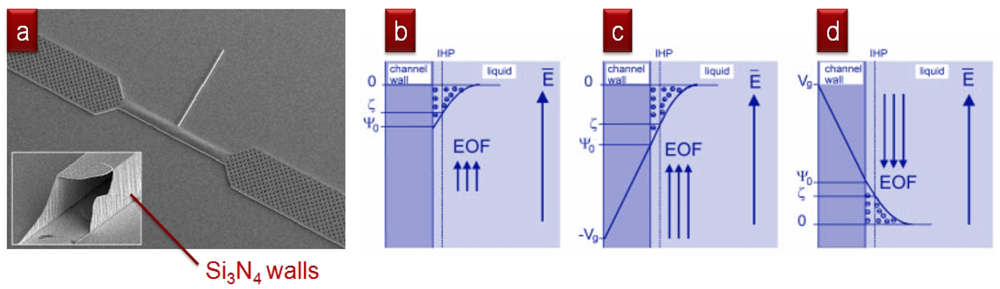
Electrokinetic valving is now only used in a very specific set of applications (mainly, capillary electrophoresis, for which electroosmotic flow is well suited) due to serious drawbacks: (1) As with all electrokinetic transport, it is strongly influenced by the surface properties of the channel (in practice, it only works reliably with glass surfaces, which happen to be difficult and expensive to micromachine); (2) It is strongly influenced by the ionic composition of the buffer: at pH > 3, the hydroxyl groups on the walls dissociate, creating negatively charged walls (with pH-dependent charge)—it is the loosely bound positive ions next to the wall that the voltages move; (3) It requires high-voltage sources and switches that are cumbersome, expensive, and unsafe; (4) Valving requires continuous flow to work: what “closes” the “valve” is the flow of buffer.
2.2. Pneumatic Microvalves
Pneumatic microvalves, introduced by Stephen Quake's group in 2000, generally utilize the deflection of a PDMS membrane to interrupt flow and has become one of the most common valve architectures; pneumatic pressure is applied to the PDMS membrane via a dedicated channel termed the “control line” or “control channel” [5-9,30-32]. The reason for their popularity is undoubtedly that they can be easily integrated with standard soft lithography processes with which most laboratories are familiar. The control channel that actuates the membrane is most frequently actuated via an external gas pressure source, but it can also be filled with a fluid to avoid air permeating into the microchannel through the membrane. Changes in the pneumatic pressure cause the valve membrane to deflect and seal against the seat. Three types of pneumatic microvalves will be discussed here: Normally-open [6,9,30,32], normally-closed [7,8], and lateral-deflection microvalves [5].
2.2.1. Normally-Open Membrane Microvalves
Normally-open membrane microvalves are designed to impede fluid flow only when the valve is activated. Upon application of positive pressure to a control line, a flexible membrane is deflected in order to stop flow through the valve. Three normally-open membrane microvalve types will be discussed in this section: Quake, plunger, and lateral-deflection membrane microvalves. Quake valves consist of three layers and route fluid in one plane, while plunger valves consist of four layers and route fluid between two planes. Finally, lateral-deflection membrane microvalves consist of only one layer, so fluid flow is inherently restricted to a single plane. However, these valves do not fully close off flow.
Quake Microvalves
The most commonly-used normally-open microvalve architecture was developed by the Quake group [6,9,30]. The microvalves consist of a control channel that overlaps the path of a flow channel, separated by a membrane which is typically 5–15 μm thick (Figure 3) [6,32]. The original design was a push-down microvalve where a rectangular-cross-section control channel was located above a semicircular-cross-section flow channel and depressed it to cut off flow [9]. Unger et al. reported flow channels 100 μm wide and 10 μm high with a minimum actuation pressure of 40 kPa to seal the channel at zero back pressure [9]. A second generation of the Quake valve used a push-up design, where a rectangular control channel is placed underneath a semicircular flow channel [6]. In the push-up design the underlying control channel inflates a planar membrane to form a hemispherical bulge that closes the semicircular flow channel above. The push-up layout allows for an increased flow channel height (from 10 μm to 55 μm) and a lower valve actuation pressure (from 40 kPa to 15 kPa for the 100 μm-wide flow channel) [6]. The push-up valve was further improved by Pandolfi and Ortiz [32] by treating the membrane with silicone oil to cause controlled chemical swelling. The treatment induces out-of-plane buckling of the membrane, reducing the actuation pressure to 8 kPa for the monostable valve and 2 kPa for the bistable valve [32]. Some of the many applications that Quake valves have been used for include PCR [33], protein separation [34], and cell sorting [35,36].
The Quake valve's reliance on a semicircular fluidic layer cross section necessitates the use of two different photoresists during fabrication of the silicon masters. The actuation channel is typically patterned with SU-8 negative photoresist while the flow channel is patterned with Shipley AZ100 XT positive photoresist [6,9,30]. The heat-induced reflow of the positive photoresist forms the semicircular flow channel. However, the flow channel height and width cannot be designed as separate parameters since the photoresist reflow process melts the entire volume of the photoresist. More recently, an alternative approach to produce SU-8 microstructures with a rounded cross-section has been reported using diffused ultraviolet light [37].
Potential drawbacks of the Quake design include difficulties in imaging and in flow characteristic determination. The semicircular roof produces a rounded water-PDMS interface that acts as a lens. The lensing severely distorts images in transmitted-light microscopy modes such as phase-contrast microscopy—the most prevailing mode of observation of live cells in culture to date. In practice, the only viable cell imaging option is fluorescence microscopy where the light source is not required to go through the sample if using an inverted microscope. Unfortunately, fluorescence microscopy can be costly—both in the dyes as well as the UV lamp and filters—and the signal fades with time and with exposure to light. In rounded-roof channels, flow characteristics are difficult to determine since (unlike for rectangular cross-sections) the equations governing flow do not have an analytical solution [38]. (If the rounded-roof is a perfect semi-circle, then an exact solution exists [38].) This leaves finite-element modeling as the only option to predict shear stress, flow resistance, etc. The curved geometry of the channel needs to be characterized for each pattern design and is not straightforward to input (especially at bends) into most modeling packages, which are standardized for rectangular walls and circular pipes. Thus, modeling of flow in microchannels made by photoresist reflow is cumbersome and highly computing-intensive for complex channel architectures.
Plunger Microvalves
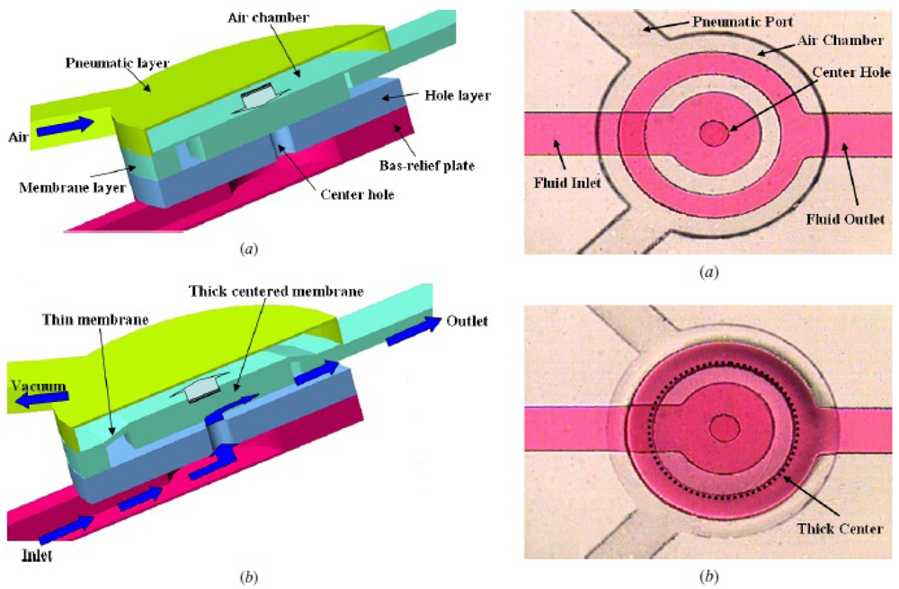
The plunger microvalve draws inspiration from a macroscale design—a rubber plunger set against a circular orifice. In this setup, reported by Sang Hoon Lee and coworkers [39], fluid flows from one layer to another through a circular through-hole in the elastomeric substrate. The microvalve, a flexible membrane actuated by a pneumatic chamber, works by flexing into the fluid layer and plugging the through-hole (Figure 4). The incorporation of a rigid SU-8 disk into the PDMS membrane enables higher pressure gain for the plunger microvalve (defined as the ratio of the rigid disk diameter to the orifice diameter squared). The ability to maintain pressure gain greater than unity allows for the development of static logic gates [40] that actuate by hydraulic pressure for on-chip digital microfluidics. One version of the plunger microvalve has been employed for the microinjection of fluid through a microneedle [41]. An alternative plunger valve design has recently been developed which is normally-open at rest and can be used to deliver a bolus of fluid orthogonal to the direction of the fluidic inlet [42].
Lateral-Deflection Membrane Microvalves
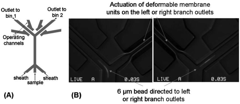
The lateral-deflection membrane microvalve is a unique type of normally-open membrane microvalve first described by Sundararajan et al. (Figure 5). As its name suggests, the lateral-deflection membrane microvalve is actuated laterally from the flow channel. The flow and control channels are located on the same layer separated by a narrow gap (<14 μm wide) that serves as an actuation membrane [5]. The most significant advantage of the lateral deflection valve design is its ease of fabrication, since only a single photolithographic layer and elastomeric replica is needed. However, as noted in a follow-up paper [31], the design is not a true valve in nature because it does not entirely seal the flow channel but is instead a flow resistor. In addition, there exist three sidewall effects within the channel cavity—top, bottom, and side—that dictate the deflection behavior of the membrane, making the system more difficult to model compared to the three-layer membrane microvalves [31]. Also, the integration of control lines onto the same plane as the flow channel reduces the available on-chip real estate for additional parallel integration. However, high-speed cell sorting has been successfully demonstrated through the pairing of a lateral-deflection membrane microvalve with a bifurcating channel junction [43].
2.2.2. Normally-Closed Membrane Microvalves
In addition to normally-open designs, membrane valves can also be fabricated to be closed at rest. Normally-closed designs include “doormat”, “curtain”, and check valves. Normally-closed valve designs have well-defined rectangular channel architecture and require the use of only one type of photoresist, which simplifies the photolithography process and eliminates the need for photoresist reflow. The trade-off is that the closed valve architecture carries the inherent risk of bonding the valve permanently closed during assembly.
There are three main strategies to circumvent the issue of permanent bonding between the valve seat and the membrane. One may choose to selectively prevent the membrane from bonding to the valve seat by using a non-PDMS valve seat (e.g., metal [12]) or a sacrificial barrier on the membrane during the bonding process [12]. These bonding prevention strategies present a unique challenge to the fabrication process that adds to its complexity. Alternately, one may choose to forgo bonding of the fluidic layer to the membrane, a strategy applied by Hosokawa et al. [7] and Li et al. [44], and instead control the valves and fluid flow by negative pressure only. However, the limitation on positive pressures can act as a significant design restriction on certain types of microfluidic devices. Therefore, a unique design approach where the trade-off between fabrication complexity and actuation flexibility could be avoided is of great interest. Finally, the microcontact printing of PDMS oligomers on oxidized PDMS has recently been reported as a method for selectively blocking PDMS-to-PDMS bonding [45].
“Doormat” Style Microvalves
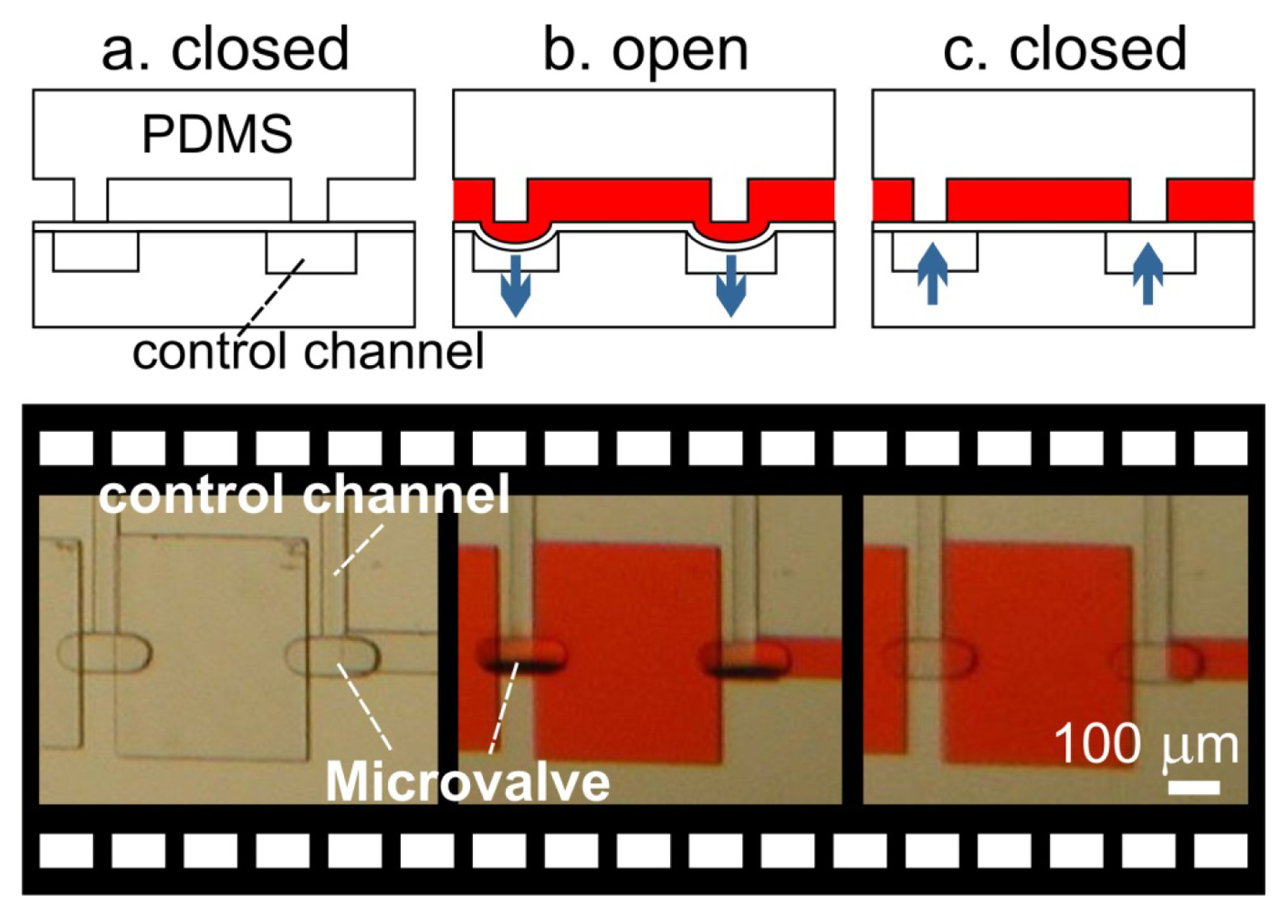
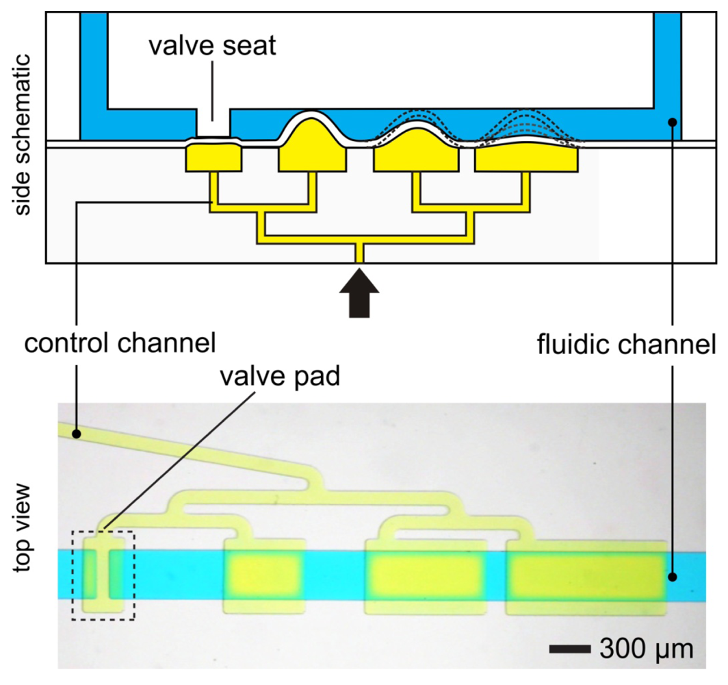
In 2000, just three months after Stephen Quake submitted his manuscript to Science and while it was still in press, Hosokawa and Maeda submitted an entirely different PDMS design (Figure 6). Here the PDMS membrane is contact-transferred as a film, “sandwiched” between the control channel and the flow channel. The valve is then formed by a small pad of PDMS membrane suspended over a control channel and is positioned under the wall separating two microchannels (hence the name “doormat”) [7,8,44,46]. As negative pressure is applied to the control channel, the membrane pad deflects downward and the two sides of the microchannel communicate under the wall. This design can be fabricated entirely with SU-8 photolithography, bypassing the need for photoresist reflow and allowing for microchannels with rectangular cross-sections. PDMS-molded channels [7,44,46] and micromachined glass [8] have been used as the materials of choice for assembling doormat microvalves. Using the closed valve architecture, micromixer arrays [44], latching valves [47], and pneumatically-actuated logical structures [47,48] have been demonstrated.
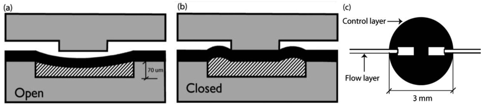
In 2003, Richard Mathies' group [8] developed a normally-closed microvalve that mirrors the design proposed by Maeda's group. Unlike Maeda's design, the membrane is sandwiched between two micromachined glass substrates (instead of PDMS). The choice of glass substrate is based on the superior surface chemical stability of glass, which allows for establishing reliable electroosmotic flow (a necessary technique for high-throughput chemical separations). Two valve designs were presented by Grover et al. [8], both with a 254 μm thick PDMS actuator membrane. A standard wet-etching process was used to fabricate the microfluidic channels on glass substrate. The first design consists of three layers—a flow layer with 20 μm-deep channels, a PDMS valve membrane, and a control layer with 70 μm-deep features. The second design sought to minimize fluidic contact with the PDMS membrane by incorporating a 210 μm-thick borosilicate glass via layer into the flow channel layer. By reducing the contact area between pumped fluid and PDMS membrane, potential for undesired protein adsorption and cell adhesion is diminished. The resultant device was able to withstand 75 kPa of fluid pressure with just 45 kPa of valve pressure. Using this valve design, complex pneumatic logic structures have been demonstrated [47,48].
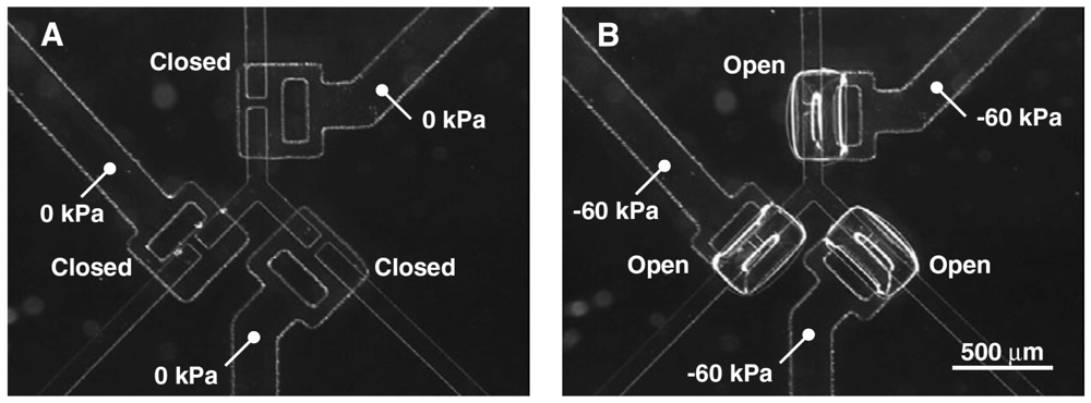
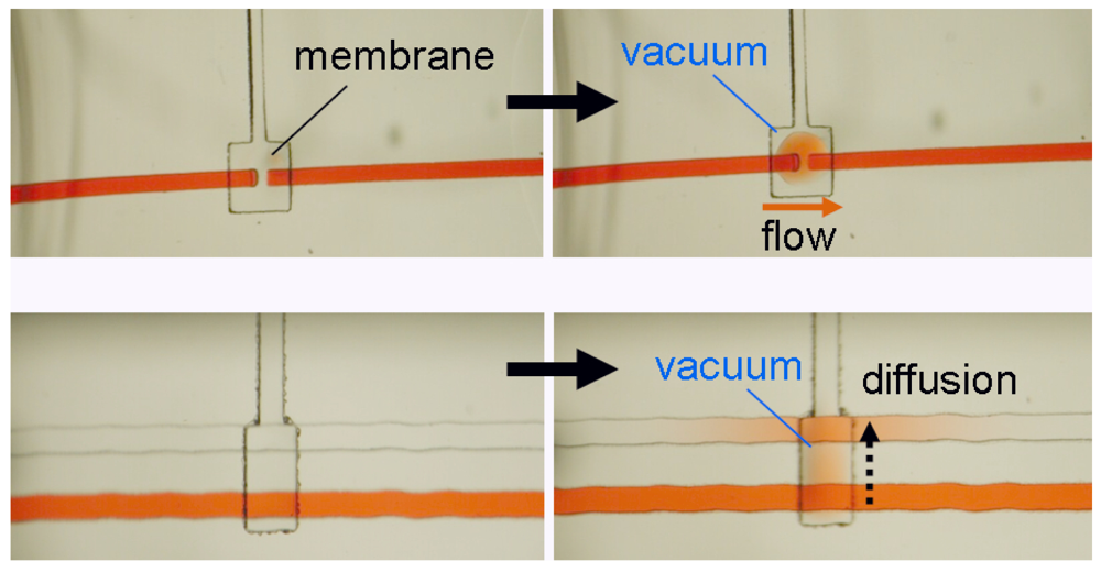
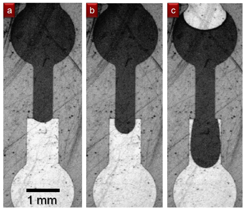
In the doormat microvalve, the deflectable membrane is sandwiched between the flow layer and the control layer. As explained above, care must be taken not to permanently bond the membrane to the valve seat. Doormat microvalves can be operated to separate two sections of the same microchannel or multiple microchannels (Figure 7). When the membrane is not deflected (square pad in the left panels in Figure 7), the valve is closed and no mass transport of red dye occurs. Application of vacuum to the control line deflects the membrane downwards, allowing mass transport by convection, diffusion, or both.
The doormat design does not have the aforementioned shortcomings of the Quake valve, and issues of bonding the membrane to the valve seat can be mitigated [7,12,44,45]. Since the valve is actuated from the channel floor, it can actuate both deep and shallow channels. The valve design benefits from all of the advantages of SU-8 microfluidics, namely: (a) The channel height is specified independently of its width; (b) The channels have rectangular cross-sections (greatly facilitating fluid dynamics modeling—both analytical and numerical); and (c) The roofs are flat (allowing for phase-contrast microscopy of cells within the channels). Microchambers enclosed by doormat microvalves have volumes that are defined only by photolithography (not by a deformed PDMS wall), so metering is limited simply by the resolution of the photolithographic process and, since the SU-8 sidewalls are straight, calculation of the volumes is trivial (Figure 8). Finally, since the valves are closed at rest, the devices can be unplugged and transported to a different location with all the fluids stored safely in microchambers.
“Curtain” Style Microvalves
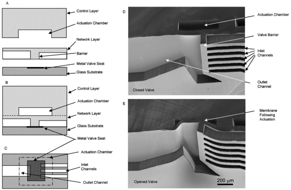
The “curtain” style microvalve developed by Irimia and Toner [12] is another normally-closed valve design (Figure 9). As opposed to the doormat design described previously, the channel barrier on the curtain valve is a microstructure integrated with the membrane layer instead of the channel layer. The membrane layer is made by standard photolithographic techniques with SU-8 photoresist. Two microstructure membranes were developed—one made by single-layer photolithography with 30 μm-high features for inlet channels, and another by multilayer photolithography with 30 μm-high inlet channels and 3 μm-high gaps as cell traps. The microstructured membrane layer is sandwiched between the control layer and the pre-patterned glass substrates. The valve seat for the membrane is a thin (50 Å) layer of chrome metal patterned onto a glass slide by sputtering to prevent irreversible bonding between the membrane layer and the glass slide. At zero pressure, the membrane sits flush with the valve seat and blocks the flow channel. In the two-layered membrane design, the leaky barrier serves as a cell trap that may be used for cell enrichment and separation [12]; positive pressure can be applied to the control layer to shut the leaky channels as well. By drawing vacuum on the control layer, the membrane and barrier(s) are lifted upward and open the fluidic passage. Cell enrichment [12] and integrated microvalve-gradient generator systems [49] have been demonstrated with this valve architecture.
2.2.3. Check Microvalves
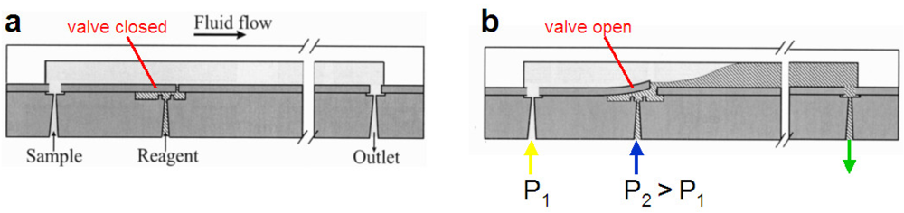
Check valves are valves that allow fluid to flow in only one direction. The mechanical part that impedes reverse flow forms a seal with the valve seat and the seal improves if the reverse pressure increases. The valve is opened by increasing the upstream pressure enough to overcome the combination of the downstream pressure and any restoring force (e.g., a spring or gravity) that is pressing the valve against the seat. Check valves can be implemented on the micron scale using traditional silicon micromachining techniques. A team at M.I.T. led by Martin Schmidt developed a micromechanical flap integrated at the end of a silicon-made nozzle (Figure 10) to control biochemical reactions of two compounds. Two nozzles (one with a check valve) led to a reaction chamber with one outlet. Pressurizing the check valve to a pressure higher than that of the chamber (determined by the pressures at the outlet and at the other inlet) deflected the flap upward [Figure 10(b)] to open the valve and produce the chemical reaction in the chamber.
This type of microvalve is expensive to develop but extremely inexpensive to commercialize (i.e., batch manufacturing results in low cost per device). Issues of concern are cost of disposal, where used equipment must be disposed with sharps, and sensitivity to dust and contamination. Fluids must be carefully filtered as the valve seat is made from a rigid material and even slight contamination can affect the integrity of the seal. These issues are only applicable to silicon fabricated valves as materials that are cheaper, less rigid, and more flexible can be used. Jeong Yong Kim et al. have designed a planar, non-silicon check microvalve that is integrated into a PDMS flow channel [51]. The check valve flaps are made of UV-crosslinked 4-HBA-DMPA-EGDMA copolymer that can withhold back pressure up to 42.2 kPa. Using hydrogel flaps with PDMS stop posts prevents stiction between the microvalve's moving parts, an issue that affects many monolithic designs [7,8,12,44]. This check valve design was used for the delivery of biocompatible materials to mouse embryo fibroblast cells [51].
2.3. Pinch Microvalves
All the above designs require the connection of the device to a vacuum supply (and sometimes also a pressurized air source), so they are not portable while functioning. Ideally, one would like to generate pressure with minimal power and using electrical circuits, which can be readily patterned and addressed with computers. Pinch microvalves have similarities to the PDMS valves reviewed above, but with two key differences: (a) Instead of being based on the deformation of a thin PDMS membrane next to the fluid-carrying microchannel, they are based on the deformation of the bulk of PDMS that forms the device; (b) Instead of being based on the remote generation of pressure, which keeps the Quake, doormat, curtain and plunger designs tethered to a differential pressure-supplying wall, they are based on the local mechanical generation of pressure.
2.3.1. Braille Pin Pinch Microvalves
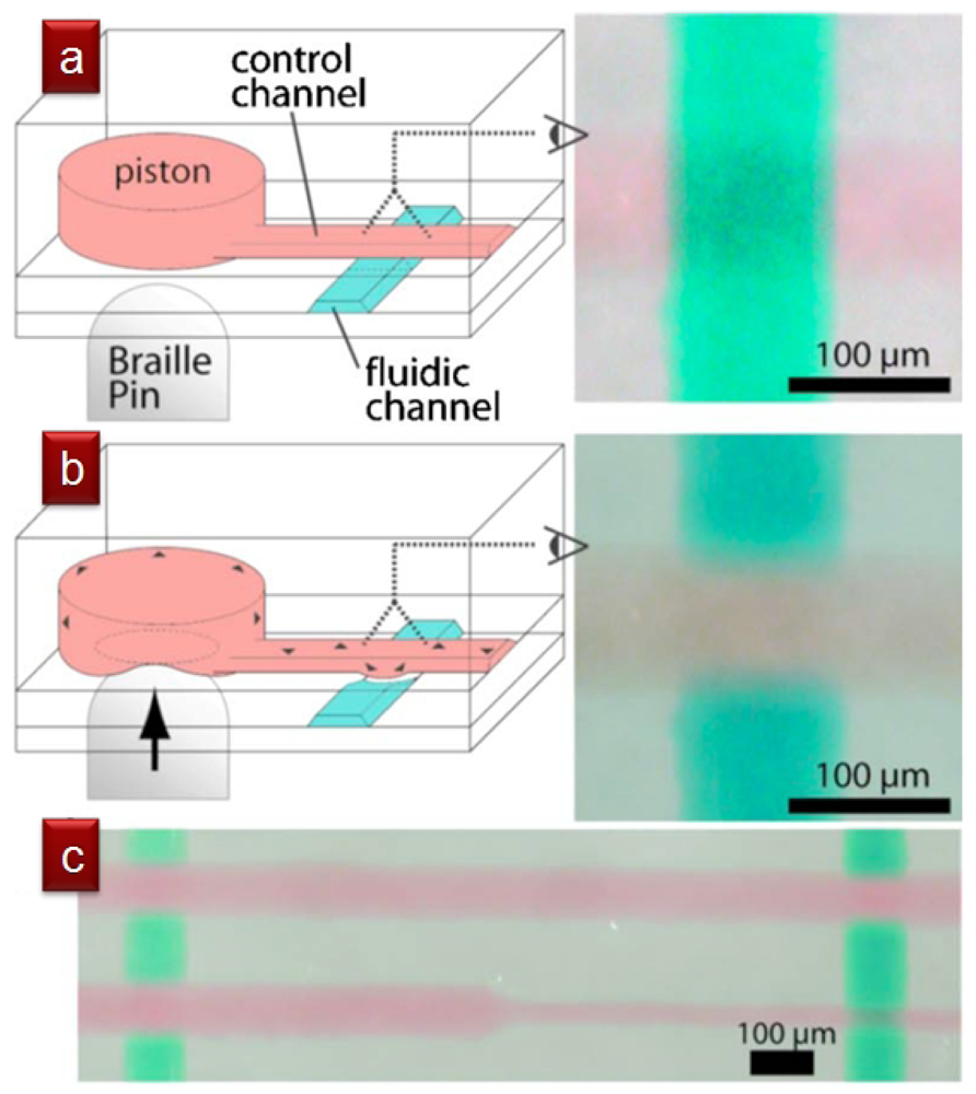
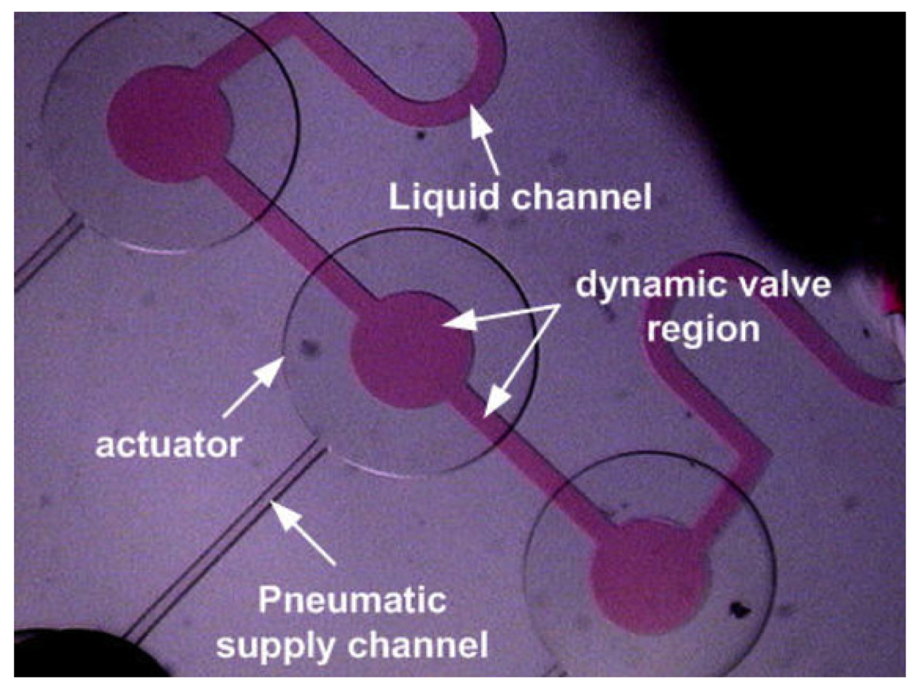
Braille pinch microvalves, developed by Shuichi Takayama's group, generate localized pressure via the mechanical pins of Braille displays, which are normally used to communicate with the blind and represent an inexpensive and easily programmable valve control method [52,53]. One limitation of these valves is that the pinching points cannot be very close to each other, with the smallest distance ultimately dictated by the thickness of the device (even if pin arrays smaller than Braille displays can be fabricated). However, the pinching points need not be the valving points. Each pin presses onto a liquid-filled reservoir (∼150 μm high, ∼900 μm in diameter), which acts as a “piston” that transmits the pressure to a membrane-based pneumatic valve (in this case, a Quake valve) at a remote location, even centimeters away. Figure 11 shows a top-down view of four intersections of pressurized control (red) and flow (green) microchannels (9 μm high and 100 μm wide, except for the 40 μm wide control channel on the lower right, which is not pinched because it is narrower). Takayama's group has demonstrated cell seeding and compartmentalization [52], as well as culture media recirculation [53], using Braille pinch microvalves.
2.3.2. Manual Pinch Microvalves
Another form of pinch microvalve is the TWIST valve developed by Weibel et al. [2], which incorporates stainless steel screws with photocurable polyurethane threads directly on PDMS replicas (Figure 12). This represents a highly manual option, but offers advantages in simple, disposable microfluidic systems.
2.4. Phase-Change Microvalves
Phase-change microvalves allow for controlling fluid flow by the phase transition of the valve material, so they do not require a pneumatic connection to the valve seat. Paraffin [10,11,22], hydrogel [20,21], ice [18] and water [19] have all been previously described as viable candidates for phase-change microvalves. Most phase-change microvalve designs incorporate a cooling or heating element [18,19] that modulates the valve's solid and fluidic phases. Hydrogel microvalves are the most flexible of the phase-change valves as they can respond to a wide variety of environmental stimuli such as temperature and acidity [20,21], while the ice microvalves are virtually contamination-free since they use the flow channel fluid to perform the valve control. One common disadvantage of phase-change microvalves is their slow actuation time from 1 to 10 min [10,18,20-22]. In most thermoresponsive phase-change microvalves, a heating element (such as indium tin oxide, or ITO, a transparent semiconductor) or a Peltier cooling element is incorporated to provide accurate and localized temperature controls. Analysis of the temperature gradient generated by the heating/cooling elements shows that significant temperature change is confined only to the area in direct contact with the element, due to the high specific heat of water. Although the slow response time of such microvalves is not critical for some applications, the delay may present an issue for certain studies where rapid fluidic switching is critical.
2.4.1. Paraffin Microvalves
Paraffin is the material of choice for many phase-change microvalves because paraffin has a low, tunable melting point [10,21] that allows for easy actuation and has a low cost that is amenable to disposable bioassay microchip designs. At the same time, solid-phase paraffin can hold up high fluidic pressure (∼276 kPa) without leakage and retains no dead volume [22]. However, the valves can typically only be used once [10,22] to restrict fluid flow; once reopened, the paraffin cannot be recovered [22]. Yang et al. devised a reusable and latchable paraffin valve by incorporating concepts of thermopneumatic and membrane microvalves (Figure 13). In their design, solid-phase paraffin is embedded into a separate chamber set atop a semicircular flow channel. The valve is actuated by the melting of the paraffin followed by pneumatic compression of the liquid paraffin that, in turn, presses down on the flow channel to shut off flow [10]. Although the design improves on some of the flaws of the one-time-use paraffin valve developed by Liu et al. [22], the system offers little distinct advantage over similarly designed pneumatic microvalves, while retaining the slow response time of paraffin valves. Incorporation of more efficient microheaters can improve the response time of the paraffin valves, but fast-response paraffin microvalves are yet to be demonstrated in the literature.
2.4.2. Polymer Microvalves
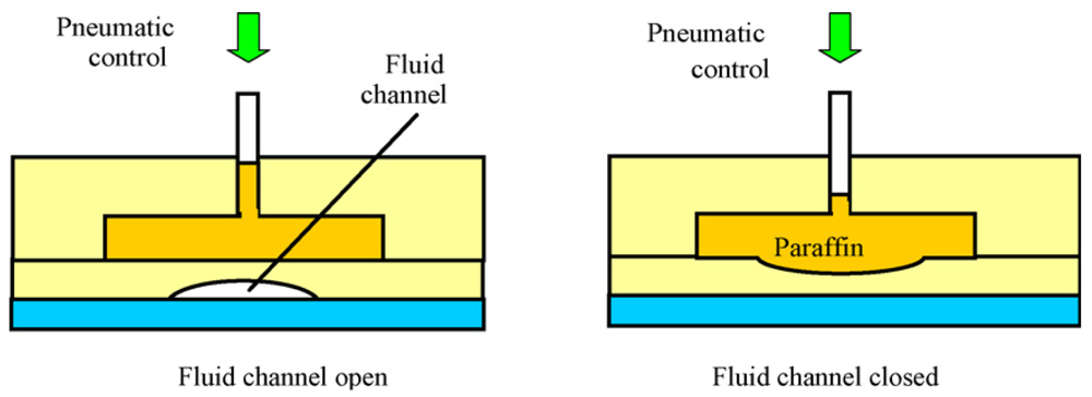
Christopher Backhouse's group at the University of Alberta in Canada has introduced temperature-sensitive polymers, polyethylene glycol (PEG) and wax, into the control channels of a doormat design valve (Figure 14). In order to flow, the polymer has to be introduced in the molten phase (expands in volume), so when it cools down to room temperature the valve is opened. Upon local heating of the valve seat, the polymer in the control channel expands, causing closure of the valve. The doormat design is open at rest, which may prove useful for certain applications.
For biochemical reactors (e.g., PCR devices) or cell culture systems, which are operative only on a very limited range of temperatures, heat-based actuation naturally raises serious concerns. However, these concerns may be addressed by placement of the valves away from critical sites and by designing heat sinks.
2.4.3. Smart Polymer Microvalves
Some polymers undergo reversible phase transitions (such as a change in volume or solubility) upon application of a stimulus (such as a change in pH, temperature or light); as the state is reversed upon removal of the stimulus, these polymers can be used as a sensor for that particular stimulus; hence they have been marketed as “smart”. (Ice, with its transition to water, is just as “smart” in that regard, but not as useful because its properties cannot be tailored by molecular design.) In 2000, a team led by Jeffrey Moore and David Beebe, then at the University of Illinois at Urbana-Champaign, was able to photopolymerize smart polymer features inside a microfluidic device [20], thus creating functional microarchitectures that change flow patterns in response to the stimulus. Step responses of 8 s to pH changes were demonstrated with a variety of microfluidic elements, including valves. Polymer posts that expand in diameter at low pH (∼5, obstructing the channel) and contract at high pH (∼8, allowing flow) could be fabricated in one channel whereas posts made of a polymer of inverse behavior could be fabricated in a branching channel, thus acting as a sorter of flow depending on pH (Figure 15). As the photopolymerization process is generally applicable to many polymers, it is not difficult to envision other types of “smart valves”.
2.5. Burst Microvalves
Burst microvalves are single-use, passive microvalves that “burst” open irreversibly when the driving pressure exceeds the flow resistance of the valve. While closing these valves requires little to no energy input, opening the valve requires energy input to overcome the valving mechanism. There are three valving schemes for burst microvalves. Capillary burst microvalves are characterized by the capillary effects of abrupt changes in fluid contact angle, forming a high-energy meniscus. A variation of this design uses centrifugal forces to overcome capillary forces. Lastly, a sacrificial membrane can be patterned over the valve seat, blocking channel access. Due to their single-use nature and simple fabrication, burst microvalves are highly desirable for disposable microfluidics in remote settings where off-chip controllers are not available.
2.5.1. Capillary Burst Microvalves
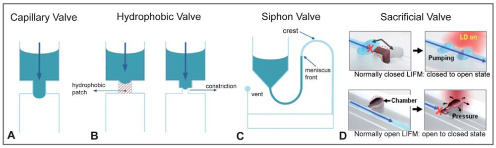
Capillary burst microvalves passively control fluid flow by increasing capillary resistance inside the microchannel. This is typically accomplished by an abrupt change in the geometry or surface chemistry of the microchannel. The high surface energy as a result of the abrupt channel change traps the liquid meniscus at the interface of the valve (Figure 16). In the geometric capillary microvalve, a straight microfluidic channel empties into a much wider valve area with diverging sidewalls [24]. Fluidic resistance greatly increases at the interface between the straight channel and the angled valve sidewall, pinning the liquid meniscus in the straight capillary channel. The liquid meniscus forms a bulge into the valve area characterized by the equilibrium contact angle, θe, with respect to the straight channel, which is dependent on the surface tension of the meniscus. Applying a driving force (such as pneumatic pressure or centripetal force) to the flow channel will increase θe. When θe exceeds the advance critical contact angle θA, the liquid meniscus bursts, thereby opening the valve [23]. The driving pressure needed to open the valve can be derived from the Young-Laplace equation [23]. Once opened, capillary microvalves cannot be recovered unless controlled slug volumes are used, such that the valve oscillates between filled and unfilled states. Capillary burst microvalves have been used to position droplets on a device for RNA amplification [56]. In another paper, capillary burst microvalves were patterned with carbon black fluoropolymer, which produced a superhydrophobic surface, thereby increasing the burst pressure of the microvalves [25].
2.5.2. Centrifugal Valves (“Lab-CD”)
To circumvent the high-voltage requirement of electrokinetic valving, Marc Madou and colleagues introduced in 2001 an original idea: to make the channels rotate so that the fluid is moved by centrifugal forces [57]. The whole device architecture and operation is constrained by this requirement, but by clever design it is possible to sequentially fill microchambers while the disk (“CD”)-shaped device is set to spin, stop, and spin again (in both directions). The CD is made of polycarbonate onto which holes and trenches can be milled with high precision. More recently, other microvalve designs have been adapted for use in this centrifugal format as well (Figure 17). The biggest hurdle for the generalization of this format seems to be its poor compatibility with standard analytical and microscopy equipment.
2.5.3. Sacrificial Membrane Burst Microvalves
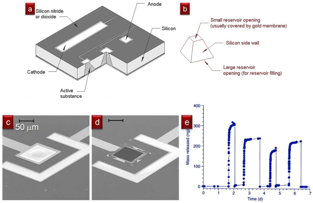
For some applications, to ensure that the valve never closes again, it may be beneficial to design single-use valves that are closed at first, open once, and stay open forever afterwards. In 1999, Robert Langer and colleagues at MIT designed a silicon-based “drug-release” microchip containing etched cavities that were capped with “sacrificial” gold membranes (Figure 18). The cavities could be filled with drug-containing solutions prior to being sealed with the membranes. The membranes could be electrochemically dissolved on-demand with the application of a small voltage (∼1 V) pulse, so that each voltage pulse controlled the release of one dose (∼25 nL) of “drug” for each cavity present in the microchip. Sacrificial membranes composed of SU-8 [27] and silicon nitride [26] have also been reported. In general, the microvalve is opened when heat [27] or electrical current [26,28] is applied to the sacrificial membrane, resulting in a change in membrane integrity and rupture of the membrane. As the microvalve is opened, debris from the disintegration of the sacrificial membrane may be released into the fluid [26], potentially contaminating the system. In addition, actuation of the microvalve may induce localized heating near the electrodes if power and timing are not properly calibrated.
2.6. “Valve-Less” Approaches
Last but not least, it is possible to route the passage of fluids even without valves (at some cost). It is worth noting that the first demonstration of valving in a PDMS device was done in 1999 using…bubbles! Isao Endo's group from RIKEN in Saitama (Japan) used dedicated microchannels to inject air into the fluid-carrying channel so as to obstruct the passage of fluids on demand [59]—an approach that is now considered impractical, since the “bubble” is much more stable when it is covered by a PDMS membrane. Many other designs of valves have been invented and many more will continue to be invented, some with less applicability to biomedical applications than others. For example, bubbles can be thermally generated with microfabricated resistors to obstruct flow (albeit with low flow resistance) and re-absorbed to allow flow [60]; however, changes in the concentrations of dissolved gases can affect cell viability and pH. For applications that can afford large volumes of reagents, it may be more practical to switch flow using flow (a very old trick)! Most often, these “flow valves” consist of using one stream to control the position of another stream on the same plane. Whitesides and colleagues have experimented with juxtaposing a stream on top of another one at a “crossroads” [61] (Figure 19); these “tangential microchannels” behave in curious ways depending on their aspect ratio (“A” in Figure 19) and can be operated as fluidic switches.
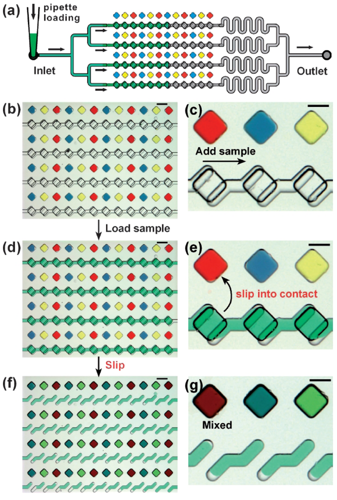
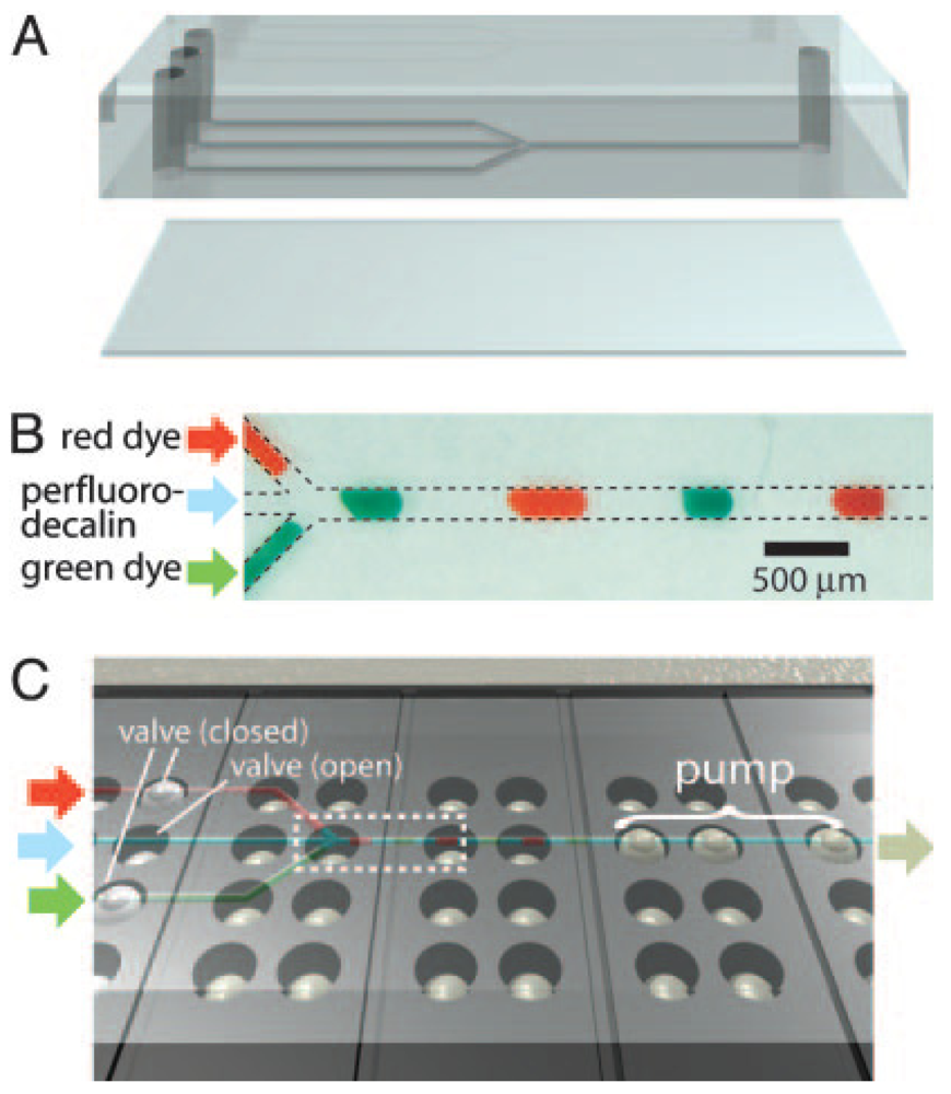
Recently, Rustem Ismagilov's group at the University of Chicago has demonstrated a clever scheme to move fluids from one microchamber to another within microfluidic devices without using pumps or valves. This scheme, called the “SlipChip”, works because the fluids to be mixed are in different planes, and the device is formed of two silanized glass plates that can slide along the dividing plane (Figure 20). A lubricating layer of fluorocarbon facilitates the relative motion of the two plates. No cross-contamination between wells is observed. The SlipChip has already been successfully used for protein crystallization screening [62] and digital PCR [63].
3. Micropumps
Like microvalves, micropumps are essential components to controlling and modulating fluid flow in microfluidic networks. Micropumps can be generally classified into two categories—active and passive. While flow rate is a measure of individual pump performance, it is not a useful metric when comparing pumps of different designs. Here we will evaluate the different types of micropumps by their own merits and provide design insights that have guided the development of these systems.
3.1. Passive Micropumps
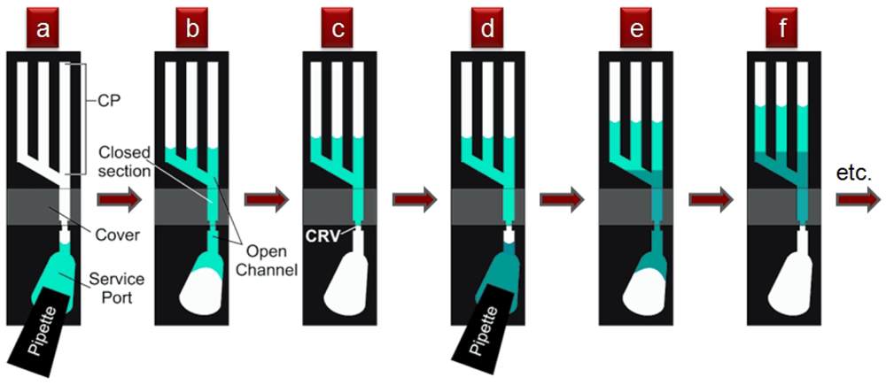
Small fluid volumes in contact with microstructured surfaces move spontaneously as a result of the interplay between the liquid's surface tension and the surface's chemical composition and topography—always in the direction that minimizes the free energies between the vapor, fluid, and solid interfaces. This behavior is most strikingly revealed in the spontaneous wetting of small channels or capillaries and has been exploited to valve and pump fluids. Early in 2002, Emmanuel Delamarche's group at IBM Zurich in Switzerland reported a capillary pump design that moved fluid from a service port until it was pinned at a capillary retention valve [65] (“CRV” in Figure 21). A second fluid could then be dispensed into the drained service port and the process could be repeated (16 sequential steps were demonstrated), as long as the channels of the capillary pump were not entirely filled. Flow rates of 220 nL/s and average flow speeds of 55 mm/s were observed in a device with a planar footprint of 100 × 100 μm2 [65].
Drawbacks of Delamarche's pumping scheme include limitation to small footprints and that the flow must be powered at all times by the surface tension of the meniscus at the end of the microchannel. A variation on this concept, presented in 2002 by David Beebe's group from the University of Wisconsin at Madison [66], eliminates these limitations by using the surface tension of droplets placed at inlets/outlets of microchannels to drive the flow (Figure 22). The flow rates are dictated by the curvature of the droplets, which in turn are controlled by the amount of fluid dispensed. This strategy allows for high-density, large-area addressing with robotic multi-pipettes, but (unlike Delamarche's scheme) it is sensitive to evaporation, has a non-constant temporal flow rate, and it is not possible to load an arbitrarily large number of units at once (to load large numbers, robotic arrayers can be used).
The obvious advantages of the surface tension-based pumping schemes are their low cost and straightforward implementation, which makes them extremely valuable for resource-poor settings. However, the pumping rate changes with time and it is not amenable to computerized control.
3.2. Active Micropumps
Active micropumps rely on an external signal to initiate and cease pumping activities. This external signal increases the complexity of device operation, but also adds the ability to control the rate and temporal behavior of the pump. This increase in control considerably augments the allowable complexity of on-chip fluidic operations.
3.2.1. Pneumatic Membrane Micropumps
Pneumatic membrane micropumps are generally based on an existing microvalve design with several such valves actuating in series to produce peristalsis in the microchannel. Briefly, a fluid volume (“bolus”) is bound between activated pumping membranes and moves unidirectionally through sequential activation of the pumping membranes. Consequently, the bolus will move away from its initial position, generating a volume displacement in the microchannel.
Like membrane microvalves, membrane micropumps can be separated into two groups based on the native (zero actuation pressure) state of the pumping elements—normally-open and normally-closed. These micropump designs can be applied to both semicircular [6,9] and rectangular [31,51,69-72] channels.
Quake Micropumps
Fluid pumping in semicircular flow channels (utilizing the aforementioned Quake valves) was first described in 2000 by Unger et al. [9]. The pump consists of three in-line pneumatic valves with individual control lines [Figure 3(b)]. In the initial design, the flow channel was 100 μm wide and 10 μm tall, separated from the pneumatic control channels by a 30 μm thick membrane. Using an actuation pressure of 50 kPa, a maximum flow rate of 2.35 nL/s was measured at 75 Hz actuation frequency. Peristaltic pumping in this membrane pump is demonstrated using a “120°” pattern, referring to the 120° temporal phase shift of the actuating membranes. In a follow-up paper [6], a push-up valve design with a channel height of 55 μm and a width between 100 μm and 600 μm replaced the original push-down design. The redesigned pump was actuated at a quarter of the pressure previously required in Unger et al. [9]. This design is the only normally-open pump that is capable of sealing the fluid volume completely inside the microchannel due to the semicircular profile of the channel. As a result, the dead volume of the pump is extremely small (∼100 pL) [73].
Normally-Open Rectangular Channel Micropumps
Micropumps based on the normally-open architecture can be incorporated into rectangular channels as well. While normally-open microvalves cannot be produced using rectangular channels due to poor sealing, such restrictions do not apply for micropumps. Although the membrane does not close the channel entirely, its deflection still causes a fluid volume displacement that results in a net transport of fluid across the microchannel. Several designs have been proposed to integrate normally-open micropumps into rectangular flow channels.
Sundararajan et al. [5] reported a laterally-deformable membrane pump that can be integrated onto a single photoresist layer with a maximum flow rate of 0.4 μL/min at 30 Hz actuation rate. Jeong and Konishi [69] developed a peristaltic pump based on three cascaded actuation channels with maximum flow rate of 73.9 nL/min actuating at 2 Hz (Figure 23). Konishi's cascaded micropump consists of small circular liquid chambers and larger circular actuator chambers that can fully shut off the fluidic path when the valve is actuated.
Doormat Micropumps
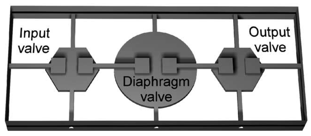
Pneumatic micropumps can also be produced using a normally-closed architecture. As with the normally-closed microvalve design, valve seats create gaps between segments of the flow channel. Actuation chambers are aligned over these valve seats, such that a deflection of an elastomeric membrane away from the valve seat creates a fluidic connection between the flow channel segments. In a design described by Grover et al. (Figure 24), a 254 μm thick PDMS membrane is sandwiched between flow and control layers made of chemically etched glass. Actuation chambers of circular and hexagonal geometry with diameters between 1 mm and 6 mm were used, corresponding to chamber volumes between 67.1 nL and 2,050 nL. For each pumping step, the actuation time was varied between 1.5 s and 10 s to allow for complete filling of the diaphragm cavity. An average stroke volume that is 82% of the actuation chamber volume was reported [8], with a maximum flow rate of 240 nL/s reported using an actuation chamber diameter of 6 mm with optimized fluid loading and emptying cycles. High volumetric flow rate can be achieved in the normally-closed configuration by increasing the size of the actuation chamber to increase stroke volume, and by optimizing the loading cycle to maximize the volume loaded [8].
Serpentine Channel Micropumps
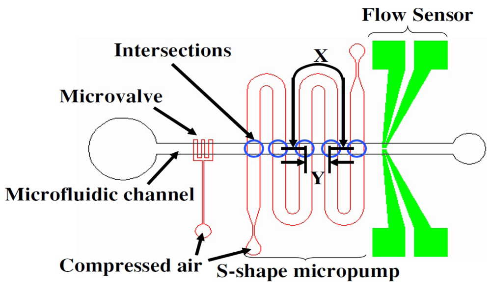
Despite the different geometry and design of the previously described micropumps, all of them require a multiplexed pneumatic source that is capable of actuating the peristaltic pattern. On the contrary, Gwo-Bin Lee's group [70,71] developed a unique serpentine channel micropump that requires only one pneumatic source to actuate (Figure 25). Pneumatic pressure passing through the serpentine channel will exhibit latency in membrane deflection towards the end of the channel so membranes actuate sequentially, moving away from the pressure source. In the pressurization cycle, the serpentine channel is filled with compressed air, causing the cross-channel membranes to deflect, generating about 2.5 cavity volumes of fluid flow through the channel. In the release cycle, the membrane is sequentially deflated from the membrane closest to the pneumatic port toward the end of the serpentine channel [70]. Actuation of the serpentine channel results in a peristaltic pumping motion with a maximum pumping rate of 7.43 μL/min at 9 Hz operational frequency and ∼138 kPa of air pressure [70]. One potential drawback to the serpentine channel micropump is the surface area needed to actuate the micropump. In order to generate pressurization latency to actuate the pump sequentially, the pneumatic channel must be made longer and narrower to increase the fluid resistance within the channel and thereby increase its latency. Incorporation of long and narrow channels may take up too much room on a PDMS chip and should be considered when designing an integrated microfluidic chip with a serpentine-shaped micropump.
Single-Stroke Micropumps
The Folch lab at the University of Washington has investigated a design principle that is based on the universal mechanical principle that small membranes respond faster than larger membranes, so they can be connected to the same pneumatic line, eliminating the delay lines that consume so much real estate in the serpentine micropumps (Figure 26) [74]. (Note that serpentine channel micropumps can also be denominated “single-stroke”, but they rely on the existence of the delay lines; we only use the term “single-stroke micropumps” to simplify the denomination of “non-serpentine micropumps that can be operated with a single control channel without delay lines”.) Upon arrival of the pressure pulse, the first valve to close is always the smallest one, and the last valve to close is always the largest one, thus producing a peristaltic wave. It matters very little whether the membranes are connected in series or in parallel: serially-connected membranes that are connected backward (such that the pressure pulse arrives first at the largest membrane) can still pump forward (i.e., the small membrane is activated first).
Check Valve Micropumps
Check valves are often used for flow rectifications purposes and commonly associated with piezoelectric micropumps [75-77]. However, they can be incorporated into pneumatic membrane micropumps as well. By incorporating check valves to restrict flow direction, single-stroke displacement pumps are possible. In 2006, Sang Hoon Lee's team described a pneumatic micropump with hydrogel check valves (Figure 27) [37]. Flow rates up to 25 μL/min [51] and displacement volumes of up to 120 nL/stroke [72] have been reported.
3.2.2. Piezoelectric Micropumps
Certain piezoelectric materials, such as lead zirconate titanate (PZT), undergo significant shape changes when supplied with an electrical current. Stress exerted by the piezoelectric material, coupled to a thin diaphragm, can be used to pump fluids. Some of the earliest designs of piezoelectric micropumps were micromachined from silicon wafers [75,76]. In these micropumps, piezoelectric disks are glued on top of a diaphragm (usually glass) directly above a pumping chamber. Pumping strokes are generated by alternating deflection of the piezo-coupled diaphragm into and away from the pumping chamber. Additionally, check valves [75-77] and diffusers/nozzles [78,79] are commonly incorporated into the flow channels to rectify flow direction.
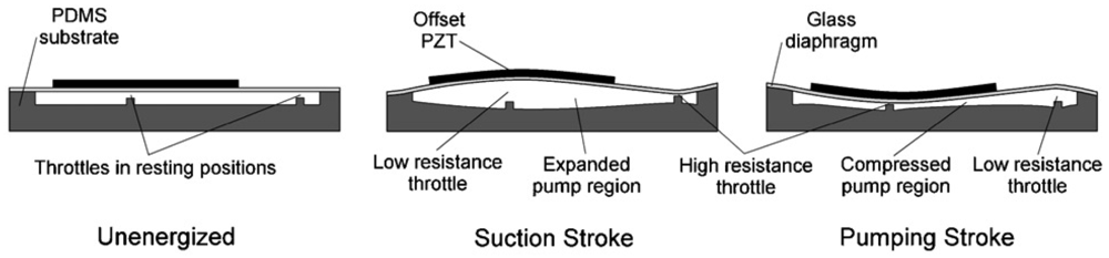
More recently, the development of piezoelectric micropumps has shifted toward using low-cost, optically transparent materials such as PDMS and PMMA, instead of micromachining glass or silicon substrates. Dynamic modulation of flow resistance (i.e., throttling) has been discussed as a potential method for flow rectification. Flow rate is inversely proportional to the fourth power of the hydraulic radius of a microchannel, so even a small reduction in a channel's cross-sectional area can produce a significant increase in flow resistance and consequently a drop in flow rate. Tan and coworkers reported the development of a microthrottling pump (MTP) [80-82] that manipulated the flow resistance using a pair of microthrottles molded into a PDMS substrate. An offset in PZT disk placement with respect to the throttles results in bimorphic flexion of the glass diaphragm such that the throttles operate out of phase from one another. When the PZT is deflected away from the channel (Figure 28), the inlet throttle has a lower resistance and thus fluid is drawn from the inlet. Conversely, when the PZT disk is compressed into the pump region, the outlet throttle has a lower resistance and thus fluid is driven toward the outlet. Pumping performance comparable to valved piezoelectric micropumps is observed at the throttling ratio (the high-to-low flow resistance ratio) of 8:1. The design by Tracey et al. [81] demonstrated the potential for integrating linear MTPs in high-density configurations. In another strategy developed by Yang and coworkers [83], a planar diffuser-nozzle channel design is used for a piezoelectric/PMMA device. When designing the pumping chamber for piezoelectric actuators, it should be noted that circular pumping chambers could induce the formation of microvortices during pump operations [80,83].
3.2.3. Braille Pin Micropumps
One major design challenge for micropump-integrated devices is their portability. Most pneumatic micropumps need to be tethered to pressure/vacuum sources, while piezoelectric micropumps require high-voltage power supplies, which typically limits these devices to laboratory benchtops. Shuichi Takayama's group at the University of Michigan at Ann Arbor has developed a micropump that can be operated using the push-pins of a Braille display [52,53], which are programmed to operate in a four-part peristaltic pattern (Figure 29). Flow rates up to ∼600 nL/min were observed, with the maximum flow rate limited by the refresh rate of the Braille pins, which is about 120 ms [52]. A hand-held, battery-operated Braille pin micropump has also been demonstrated for use in cell culture [53].
Although Braille pin micropumps have low power consumption and can achieve complete detachment from the benchtop, integration of these micropumps onto microfluidic chips is less flexible compared to other designs. Commercially available Braille pin displays have limited configurations and pin-spacing constraints (due to their design requirement to be “readable” by the fingers of the visually-impaired). This wide spacing between actuators (on the scale of microfluidic devices) renders high-density packing of microfludic networks impossible. Also, the effects of localized PDMS distortion within microfluidic devices deserves further investigation.
3.2.4. Electrochemical Micropumps
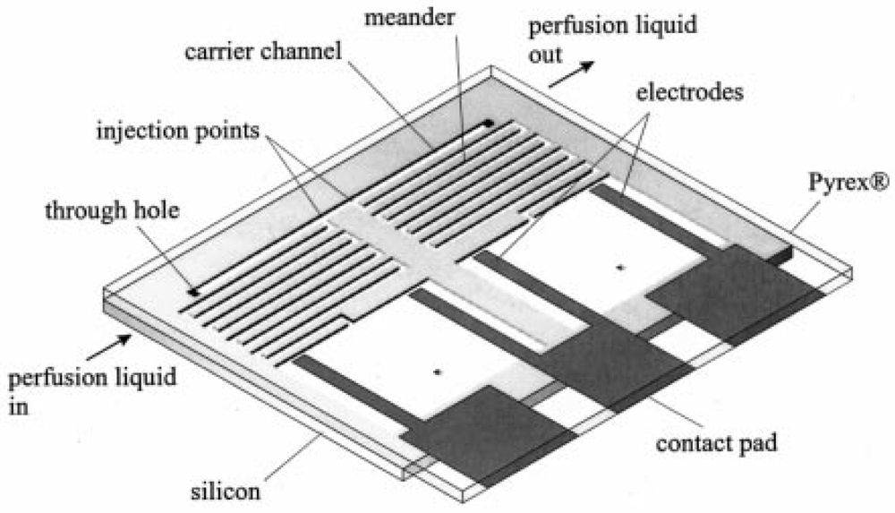
In 1999, a group led by Piet Bergveld at the University of Twente reported the development of a micromachined dosing system that uses the gas generated from the electrolysis of an aqueous solution of KNO3 to pump sample fluid through a microchannel [84,85]. The Twente micropump has a very simple design (Figure 30)—a large reservoir containing two patterned electrodes connected to a meandering microchannel. By adjusting the current amplitude and pulse, flow rates ranging from 0.8 nL/min to 4 nL/min were reported. Although continuous flow is possible with the Twente pump, flow is limited by the amount of gas that can be generated from electrolysis. Once the electrodes become supersaturated with the gas products, flow rate drops to zero and the pump is rendered inoperable.
Another issue with the Twente micropump is the lack of separation between the sample and pumping fluids and the potential cross-contamination between the sample fluid, pumping fluid, and electrolysis products. A more recent electrochemical micropump design overcomes this problem by providing two degrees of separation between the electrolysis chamber and the flow channel. Here, both elements are coupled to a sealed hydraulic chamber separated by a flexible membrane [86]. However, pumping is limited to a maximum of 40 min under optimal conditions [86].
3.2.5. Electroosmotic Micropumps
Electroosmotic flow (EOF) is the bulk motion of liquid resulting from an applied electric field across a porous material, capillary, membrane, or microchannel with charged walls. The simplest microfluidic EOF pumps consist of a microchannel with electrodes submerged in fluid reservoirs at either end [87,88]. When a DC electric field is applied across the electrodes, a high force is experienced at the microchannel walls, resulting in the movement of charge and fluid through the microchannel. As an alternative to using conventional wire electrodes, J. Michael Ramsey's group investigated the integration of thin metal microelectrodes into such channels [89]. This was achieved by patterning titanium-gold electrodes on glass using photolithography and then bonding the glass to PDMS. The gas-permeable nature of PDMS is critical for the removal of gas generated on the electrodes by electrolysis. With this design, electric field-free pumping was demonstrated in the sections of the microchannel outside of the electrode pair with pumping velocity dependent on applied voltage rather than field strength. However, the flow rates and pressures generated by such micropumps are rather low.
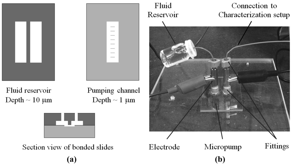
In order to maximize the pressure capacity, flow rate, and thermodynamic efficiency of a planar EOF pump, Juan Santiago's group designed a pumping channel that is wide, short, and very shallow (40 mm × 11 μm × 0.9 μm) [90]. In order to improve the structural integrity of the channel, eight parallel ribs were added running parallel to the direction of flow. The pump design that they reported composed of two layers of wet-etched soda-lime glass that are thermally bonded together (Figure 31) and was able to produce a maximum pressure of ∼33 kPA and a maximum flow rate of 15 μL/min at 1 kV. In addition to its ability to produce these high pressures, the EOF micropump also benefits from a simple design with no moving parts and the ability to work with fluids over a wide range of conductivities.
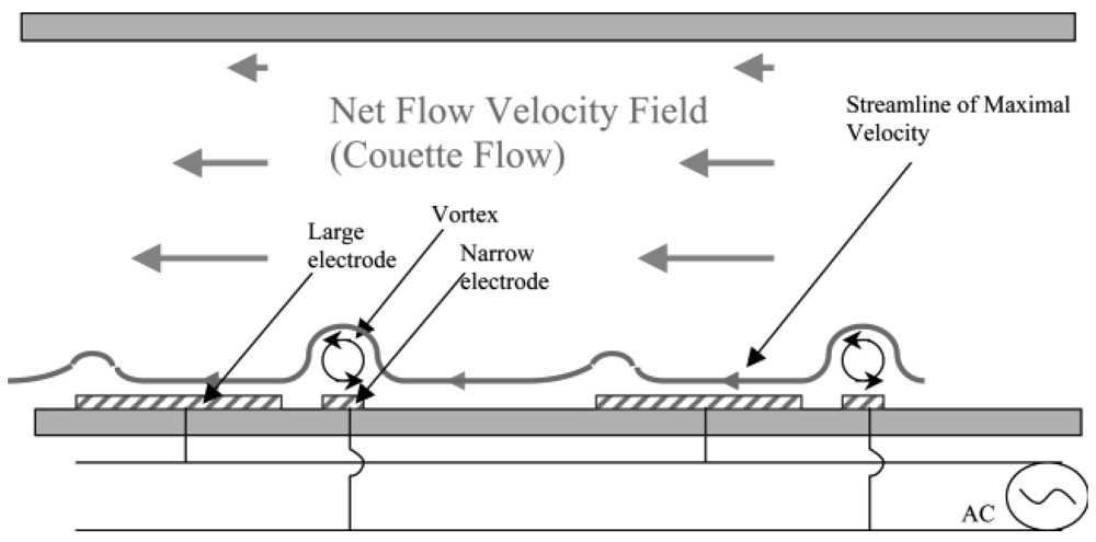
While the electric double layer (EDL) of charge necessary to produce DC electroosmotic flow is caused by the deprotonation of the microchannel surface, an alternative method of generating an EDL between asymmetric electrodes and inducing flow via AC electric fields was proposed in 1999 [91] and successfully demonstrated soon after in open [92] and closed [93] microchannels. Interdigitated electrode arrays are arranged to produce pairs of asymmetric electrodes. Upon application of an AC voltage between the electrodes, a net flow is generated in the direction from the small to the large electrode (Figure 32). Using this design, large flow velocities in excess of 450 μm/s near the electrode surfaces powered by less than 5 VRMS of AC voltage have been reported [94].
3.2.6. Acoustic Micropumps
Acoustic streaming, like electroosmosis, allows for directed flow in simple microchannels with no valves or other moving parts. However, it is less efficient than EOF pumping in terms of flow velocity and effective pressure as microchannel dimensions are decreased [96]. On the other hand, acoustic streaming does not require the channel walls to be charged or for the solution to match a particular ion content or pH. Furthermore, in pumping biological molecules and cells, there is less concern over the samples sticking to the channel walls. In 2000, acoustic actuation was used to generate directed pumping of fluid in a planar microfluidic circuit via quartz wind acoustic streaming [97]. However, this pump design utilized large channels (1.6 × 1.6 mm2) and could only pump against a maximum backpressure of 0.13 Pa.
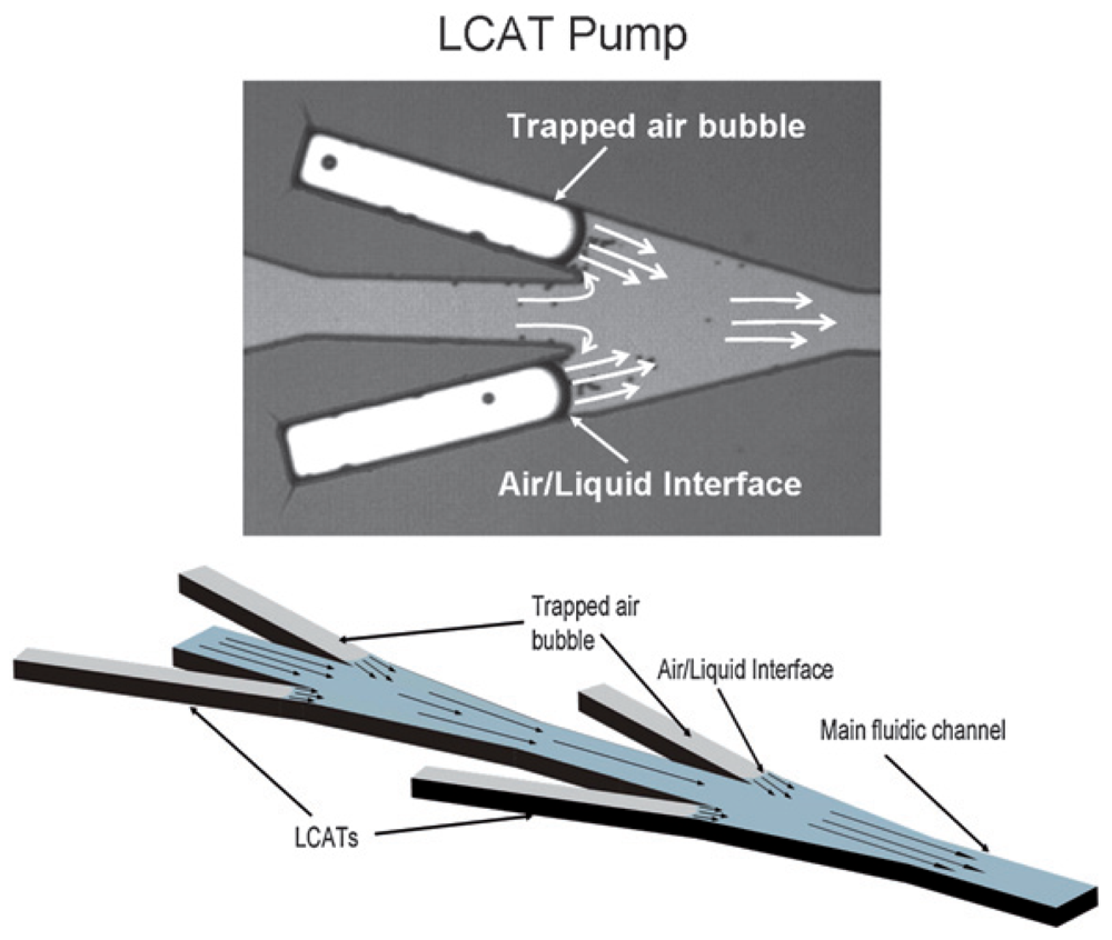
Andrea Prosperetti's group has demonstrated the pumping of fluid through millimeter-scale tubes based on the growth and collapse of bubbles [98-100]. More recently, Abraham Lee's group applied similar concepts into a planar microfluidic format, creating a lateral cavity acoustic transducer (LCAT) [101-103]. The LCAT uses bubbles trapped in the lateral cavities of their device during fluid filling, which are then excited by the acoustic field generated by an external piezoelectric buzzer (Figure 33). As long as the surface tension forces on the bubble remain greater than the maximum resonance amplitude, the bubbles stay trapped in place for the duration of pump operation. A maximum pumping pressure of 350 Pa was demonstrated in a device using 80 sets of 15° angled cavity pairs and a square-wave driving signal of 35 kHz and 25 Vpp [103].
3.2.7. Magnetohydrodynamic Micropumps
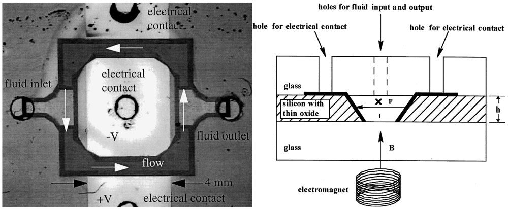
Magnetohydrodynamic micropumps drive fluid flow in conductive liquids which are subjected to perpendicular applied electric and magnetic fields across a microchannel. A resulting Lorentz force is generated on the liquid perpendicular to the direction of both the electric and magnetic fields, therefore causing the fluid to be pumped through the microchannel. An early magnetohydrodynamic micropump was demonstrated in which permanent magnets were used to generate the magnetic field, while a DC electric field was produced using microfabricated aluminum electrodes oriented in a perpendicular direction [104]. However, bubbles generated by electrolysis may impede flow and therefore limit the usefulness of such designs. Lemoff and Lee [105] avoided this problem using AC current injection, while also using an electromagnet rather than permanent magnets (Figure 34). At sufficiently high frequencies, the electrolysis reactions are reversed rapidly such that bubbles are unable to form. An AC magnetic field is generated by the electromagnet in synchrony with the current source such that the direction of the Lorentz force remains unchanged. Using this design, a 600 mA current could be passed through 1 M NaCl solution without generating bubbles using a frequency of 1,000 kHz. This solution was pumped with a maximum flow velocity of 1.51 mm/s and a flow rate of 18.3 μL/min. However, such designs may still generate large quantities of heat.
3.2.8. Electrohydrodynamic Micropumps
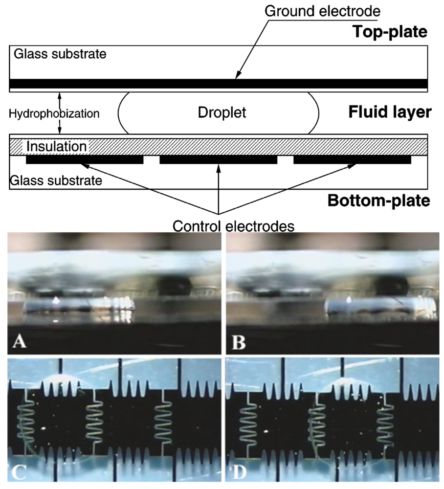
Electrowetting is the change in contact angle between a solid and electrolyte resulting from the application of an electric field between the two. In microfluidics, it is commonly used to manipulate discrete droplets of fluid over an array of electrodes in what is known as digital microfluidics. This area of microfluidics has been pioneered by the groups of Richard Fair at Duke University and Chang-Jin Kim at the University of California at Los Angeles. Because the traditional method of electrowetting by immersing a wire electrode into a droplet would not be practical for microfluidics, Fair's group developed a sandwich design in 2000 [106] in which the fluid is located between two parallel plates (Figure 35). In this design, the bottom plate consists of patterned control electrodes while the top plate is homogenously patterned with one continuous ground electrode. Furthermore, the top ground electrode is made using transparent indium-tin-oxide (ITO) in order to facilitate optical imaging. Using this design, they were able to demonstrate the splitting, merging, and dispensing of droplets in silicone oil media. Because the electrodes are covered with a hydrophobic coating, this is commonly referred to as electrowetting on dielectric (EWOD). In parallel work, Kim's group demonstrated the use of non-dielectric electrowetting and EWOD to handle aqueous liquid in microfluidic devices with air as a surrounding medium [107]. Using EWOD, they were able to demonstrate the creation, transporting, cutting, and merging of liquid droplets [108]. More recently, Aaron Wheeler's group at the University of Toronto has successfully demonstrated the culture of both non-adherent [109] and adherent mammalian [110] cells in a digital microfluidic format.
Dielectrophoresis (DEP), the force applied to polar liquids in the presence of non-uniform electric fields, has also been utilized for digital microfluidics. While DEP had previously been demonstrated to move water droplets in one dimension on sandwiched plates [112] and open-surfaces [113], Peter Cascoyne's group first reported the movement, injection, and fusion of droplets on a two-dimensional array of electrodes using DEP in 2003 [114]. Their device consisted of an 8 × 8 array of titanium-gold microelectrodes, which were electrically passivated and then further covered with a hydrophobic coating (Figure 36). Individual electrodes were energized with AC signals of 180 Vpp and frequencies of 5–500 kHz, causing adjacent droplets to move towards the actuated electrodes. Droplets were similarly metered from a closely positioned micropipette injector and fused with other droplets. For certain applications, DEP may be advantageous to EWOD as the droplets are not constrained by an upper plate and may still be actuated even when surrounded by an ambient liquid with similar hydrodynamic properties [115].
3.2.9. Gas Permeation Micropumps
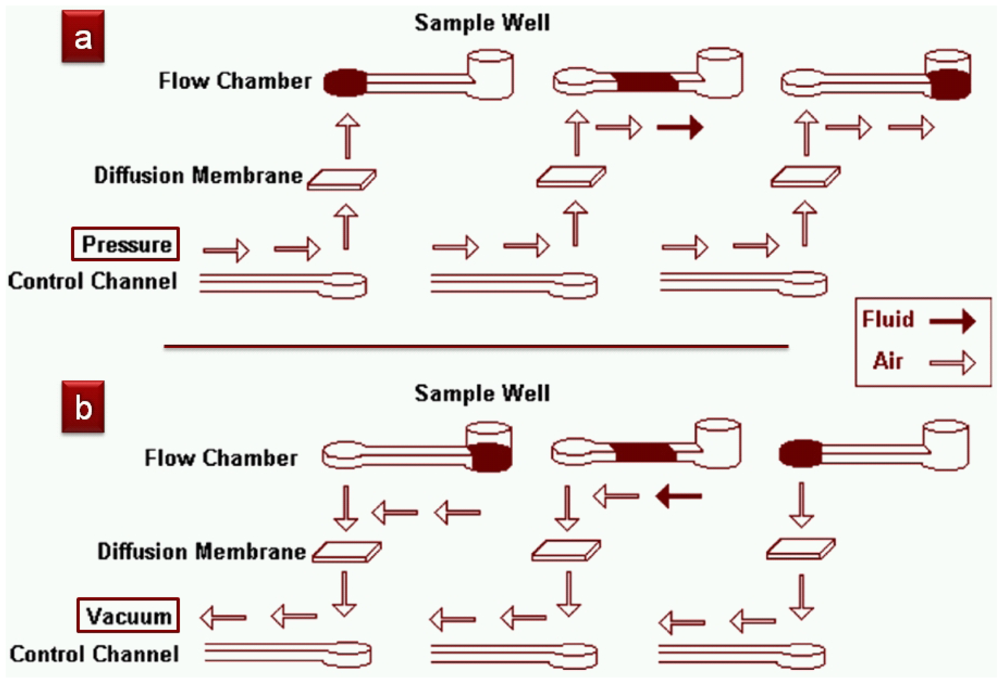
PDMS is extremely permeable to gases—one can inject air into a dead-ended microchannel with a syringe and the air … disappears! (Well, it goes into the PDMS bulk). This same concept, in reverse, has been applied to the pumping of fluids: remove all of the residual gas that is present in PDMS (by first placing the device in a vacuum jar for 15–20 min) and it will create a local vacuum in the microchannels. This simple idea was first applied by Mizuo Maeda's group from RIKEN in Japan to run biochemical assays (Figure 37) in 2004 but it is now used by many groups elsewhere. Unfortunately, the pump's pumping rate decays exponentially with time as the air reservoir gets gradually refilled (operation times of >15 min were reported).
In 2006, Bruce Gale's group at the University of Utah designed a different pump based on similar principles [117]. Here the idea was to inject air into microchannels at very small rates such that the air can in turn push plugs of fluids around (Figure 38). To add a high resistance to air flow, they simply placed a PDMS membrane of the right thickness (the study compared membranes of 100 μm, 45 μm, and 25 μm thicknesses). This pumping scheme is very robust but is incompatible with applications that are sensitive to bubbles (e.g., cells die if exposed to a bubble or even in the proximity of an air bubble, where the CO2 concentration is not adequate).
4. Conclusions
A thorough overview of the wide variety of microvalve and micropump designs available for BioMEMS applications has been presented. While most of these designs are used to control fluids in traditional closed microchannels, unique microfluidic formats like the SlipChip, Lab-CD, and digital microfluidics have emerged as well, each with their own unique strengths and weaknesses. There are no standardized measures of performance for microvalves and micropumps and each type of design varies greatly based on operating principle, materials, cost, ease-of-fabrication, portability, bio-compatibility, and reusability. The particular properties that make a valve or pump design attractive for one specific application may also render it completely unusable in another situation. Therefore, these properties must be considered as a whole in determining the appropriateness of a given design for a particular biomedical application.


Acknowledgments
We would like to thank Christopher Sip for helpful feedback during the preparation of this manuscript. Albert Folch is grateful to the following authors who contributed figures for the upcoming textbook and that have been re-used in this work: David Beebe, Albert van den Berg, Greg Boggy, Emmanuel Delamarche, Bruce Gale, Nianzhen Li, Jeffrey Moore, Stephen Quake, J. Michael Ramsey, Juan Santiago, Shuichi Takayama, Mehmet Toner, Joel Voldman, and George Whitesides.
References
- Pemble, C.M.; Towe, B.C. A miniature shape memory alloy pinch valve. Sens. Actuat. A 1999, 77, 145–148. [Google Scholar]
- Weibel, D.B.; Siegel, A.C.; Lee, A.; George, A.H.; Whitesides, G.M. Pumping fluids in microfluidic systems using the elastic deformation of poly(dimethylsiloxane). Lab Chip 2007, 7, 1832–1836. [Google Scholar]
- Weibel, D.B.; Kruithof, M.; Potenta, S.; Sia, S.K.; Lee, A.; Whitesides, G.M. Torque-actuated valves for microfluidics. Anal. Chem. 2005, 77, 4726–4733. [Google Scholar]
- Pilarski, P.M.; Adamia, S.; Backhouse, C.J. An adaptable microvalving system for on-chip polymerase chain reactions. J. Immunol. Meth. 2005, 305, 48–58. [Google Scholar]
- Sundararajan, N.; Kim, D.; Berlin, A.A. Microfluidic operations using deformable polymer membranes fabricated by single layer soft lithography. Lab Chip 2005, 5, 350–354. [Google Scholar]
- Studer, V.; Hang, G.; Pandolfi, A.; Ortiz, M.; Anderson, W.F.; Quake, S.R. Scaling properties of a low-actuation pressure microfluidic valve. J. Appl. Phys. 2004, 95, 393–398. [Google Scholar]
- Hosokawa, K.; Maeda, R. A pneumatically-actuated three-way microvalve fabricated with polydimethylsiloxane using the membrane transfer technique. J. Micromech. Microeng. 2000, 10, 415–420. [Google Scholar]
- Grover, W.H.; Skelley, A.M.; Liu, C.N.; Lagally, E.T.; Mathies, R.A. Monolithic membrane valves and diaphragm pumps for practical large-scale integration into glass microfluidic devices. Sens. Actuat. B 2003, 89, 315–323. [Google Scholar]
- Unger, M.A.; Chou, H.P.; Thorsen, T.; Scherer, A.; Quake, S.R. Monolithic microfabricated valves and pumps by multilayer soft lithography. Science 2000, 288, 113–116. [Google Scholar]
- Yang, B.Z.; Lin, Q. A latchable microvalve using phase change of paraffin wax. Sens. Actuat. A 2007, 134, 194–200. [Google Scholar]
- Yoo, J.C.; Choi, Y.J.; Kang, C.J.; Kim, Y.S. A novel polydimethylsiloxane microfluidic system including thermopneumatic-actuated micropump and paraffin-actuated microvalve. Sens. Actuat. A 2007, 139, 216–220. [Google Scholar]
- Irimia, D.; Toner, M. Cell handling using microstructured membranes. Lab Chip 2006, 6, 345–352. [Google Scholar]
- van der Wijngaart, W.; Chugh, D.; Man, E.; Melin, J.; Stemme, G. A low-temperature thermopneumatic actuation principle for gas bubble microvalves. J. Microelectromech. Syst. 2007, 16, 765–774. [Google Scholar]
- Lee, D.E.; Soper, S.; Wang, W.J. Design and fabrication of an electrochemically actuated microvalve. Microsyst. Technol. 2008, 14, 1751–1756. [Google Scholar]
- Kaigala, G.V.; Hoang, V.N.; Backhouse, C.J. Electrically controlled microvalves to integrate microchip polymerase chain reaction and capillary electrophoresis. Lab Chip 2008, 8, 1071–1078. [Google Scholar]
- Jacobson, S.C.; Ermakov, S.V.; Ramsey, J.M. Minimizing the number of voltage sources and fluid reservoirs for electrokinetic valving in microfluidic devices. Anal. Chem. 1999, 71, 3273–3276. [Google Scholar]
- Schasfoort, R.B.M.; Schlautmann, S.; Hendrikse, L.; van den Berg, A. Field-effect flow control for microfabricated fluidic networks. Science 1999, 286, 942–945. [Google Scholar]
- Gui, L.; Liu, J. Ice valve for a mini/micro flow channel. J. Micromech. Microeng. 2004, 14, 242–246. [Google Scholar]
- Baroud, C.N.; Delville, J.P.; Gallaire, F.; Wunenburger, R. Thermocapillary valve for droplet production and sorting. Phys. Rev. E 2007, 75, 046302. [Google Scholar]
- Yu, Q.; Bauer, J.M.; Moore, J.S.; Beebe, D.J. Responsive biomimetic hydrogel valve for microfluidics. Appl. Phys. Lett. 2001, 78, 2589–2591. [Google Scholar]
- Liu, C.W.; Park, J.Y.; Xu, Y.G.; Lee, S. Arrayed ph-responsive microvalves controlled by multiphase laminar flow. J. Micromech. Microeng. 2007, 17, 1985–1991. [Google Scholar]
- Liu, R.H.; Bonanno, J.; Yang, J.N.; Lenigk, R.; Grodzinski, P. Single-use, thermally actuated paraffin valves for microfluidic applications. Sens. Actuat. B 2004, 98, 328–336. [Google Scholar]
- Cho, H.; Kim, H.Y.; Kang, J.Y.; Kim, T.S. How the capillary burst microvalve works. J. Colloid Interface Sci. 2007, 306, 379–385. [Google Scholar]
- Chen, J.M.; Huang, P.C.; Lin, M.G. Analysis and experiment of capillary valves for microfluidics on a rotating disk. Microfluid. Nanofluid. 2008, 4, 427–437. [Google Scholar]
- Riegger, L.; Mielnik, M.M.; Gulliksen, A.; Mark, D.; Steigert, J.; Lutz, S.; Clad, M.; Zengerle, R.; Koltay, P.; Hoffmann, J. Dye-based coatings for hydrophobic valves and their application to polymer labs-on-a-chip. J. Micromech. Microeng. 2010, 20, 045021. [Google Scholar]
- Allain, M.; Berthier, J.; Basrour, S.; Pouteau, P. Electrically actuated sacrificial membranes for valving in microsystems. J. Micromech. Microeng. 2010, 20, 035006. [Google Scholar]
- Moreno, J.M.; Quero, J.M. A novel single-use su-8 microvalve for pressure-driven microfluidic applications. J. Micromech. Microeng. 2010, 20, 015005. [Google Scholar]
- Santini, J.T.; Cima, M.J.; Langer, R. A controlled-release microchip. Nature 1999, 397, 335–338. [Google Scholar]
- Harrison, D.J.; Fluri, K.; Seiler, K.; Fan, Z.H.; Effenhauser, C.S.; Manz, A. Micromachining a miniaturized capillary electrophoresis-based chemical-analysis system on a chip. Science 1993, 261, 895–897. [Google Scholar]
- Thorsen, T.; Maerkl, S.J.; Quake, S.R. Microfluidic large-scale integration. Science 2002, 298, 580–584. [Google Scholar]
- Lee, S.J.; Chan, J.C.Y.; Maung, K.J.; Rezler, E.; Sundararajan, N. Characterization of laterally deformable elastomer membranes for microfluidics. J. Micromech. Microeng. 2007, 17, 843–851. [Google Scholar]
- Pandolfi, A.; Ortiz, M. Improved design of low-pressure fluidic microvalves. J. Micromech. Microeng. 2007, 17, 1487–1493. [Google Scholar]
- Liu, J.; Enzelberger, M.; Quake, S. A nanoliter rotary device for polymerase chain reaction. Electrophoresis 2002, 23, 1531–1536. [Google Scholar]
- Wang, Y.C.; Choi, M.N.; Han, J.Y. Two-dimensional protein separation with advanced sample and buffer isolation using microfluidic valves. Anal. Chem. 2004, 76, 4426–4431. [Google Scholar]
- Fu, A.Y.; Chou, H.P.; Spence, C.; Arnold, F.H.; Quake, S.R. An integrated microfabricated cell sorter. Anal. Chem. 2002, 74, 2451–2457. [Google Scholar]
- Studer, V.; Jameson, R.; Pellereau, E.; Pepin, A.; Chen, Y. A microfluidic mammalian cell sorter based on fluorescence detection. Microelectron. Eng. 2004, 73-74, 852–857. [Google Scholar]
- Futai, N.; Gu, W.; Takayama, S. Rapid prototyping of microstructures with bell-shaped cross-sections and its application to deformation-based microfluidic valves. Adv. Mater. 2004, 16, 1320–1323. [Google Scholar]
- White, F.M. Fluid Mechanics; McGraw-Hill: New York, NY, USA, 2010. [Google Scholar]
- Baek, J.Y.; Park, J.Y.; Ju, J.I.; Lee, T.S.; Lee, S.H. A pneumatically controllable flexible and polymeric microfluidic valve fabricated via in situ development. J. Micromech. Microeng. 2005, 15, 1015–1020. [Google Scholar]
- Weaver, J.A.; Melin, J.; Stark, D.; Quake, S.R.; Horowitz, M.A. Static control logic for microfluidic devices using pressure-gain valves. Nat. Phys. 2010, 6, 218–223. [Google Scholar]
- Lee, S.; Jeong, W.; Beebe, D.J. Microfluidic valve with cored glass microneedle for microinjection. Lab Chip 2003, 3, 164–167. [Google Scholar]
- Sip, C.G.; Folch, A. An open-surface micro-dispenser valve for the local stimulation of conventional tissue cultures. Proceedings of the 14th International Conference on Miniaturized Systems for Chemistry and Life Sciences (microTAS), Groningen, The Netherlands, 3–7 October 2010; pp. 1778–1780.
- Abate, A.R.; Agresti, J.J.; Weitz, D.A. Microfluidic sorting with high-speed single-layer membrane valves. Appl. Phys. Lett. 2010, 96, 203509. [Google Scholar]
- Li, N.; Hsu, C.H.; Folch, A. Parallel mixing of photolithographically defined nanoliter volumes using elastomeric microvalve arrays. Electrophoresis 2005, 26, 3758–3764. [Google Scholar]
- Mosadegh, B.; Tavana, H.; Lesher-Perez, S.C.; Takayama, S. High-density fabrication of normally closed microfluidic valves by patterned deactivation of oxidized polydimethylsiloxane. Lab Chip 2011, 11, 738–742. [Google Scholar]
- Cooksey, G.A.; Sip, C.G.; Folch, A. A multi-purpose microfluidic perfusion system with combinatorial choice of inputs, mixtures, gradient patterns, and flow rates. Lab Chip 2009, 9, 417–426. [Google Scholar]
- Grover, W.H.; Ivester, R.H.; Jensen, E.C.; Mathies, R.A. Development and multiplexed control of latching pneumatic valves using microfluidic logical structures. Lab Chip 2006, 6, 623–631. [Google Scholar]
- Jensen, E.C.; Grover, W.H.; Mathies, R.A. Micropneumatic digital logic structures for integrated microdevice computation and control. J. Microelectromech. Syst. 2007, 16, 1378–1385. [Google Scholar]
- Irimia, D.; Liu, S.Y.; Tharp, W.G.; Samadani, A.; Toner, M.; Poznansky, M.C. Microfluidic system for measuring neutrophil migratory responses to fast switches of chemical gradients. Lab Chip 2006, 6, 191–198. [Google Scholar]
- Voldman, J.; Gray, M.L.; Schmidt, M.A. An integrated liquid mixer/valve. J. Microelectromech. Syst. 2000, 9, 295–302. [Google Scholar]
- Kim, J.; Baek, J.; Lee, K.; Park, Y.; Sun, K.; Lee, T.; Lee, S. Photopolymerized check valve and its integration into a pneumatic pumping system for biocompatible sample delivery. Lab Chip 2006, 6, 1091–1094. [Google Scholar]
- Gu, W.; Zhu, X.Y.; Futai, N.; Cho, B.S.; Takayama, S. Computerized microfluidic cell culture using elastomeric channels and braille displays. Proc. Natl. Acad. Sci. USA 2004, 101, 15861–15866. [Google Scholar]
- Futai, N.; Gu, W.; Song, J.W.; Takayama, S. Handheld recirculation system and customized media for microfluidic cell culture. Lab Chip 2006, 6, 149–154. [Google Scholar]
- Gu, W.; Chen, H.; Tung, Y.C.; Meiners, J.C.; Takayama, S. Multiplexed hydraulic valve actuation using ionic liquid filled soft channels and braille displays. Appl. Phys. Lett. 2007, 90. [Google Scholar] [CrossRef]
- Beebe, D.J.; Moore, J.S.; Bauer, J.M.; Yu, Q.; Liu, R.H.; Devadoss, C.; Jo, B.H. Functional hydrogel structures for autonomous flow control inside microfluidic channels. Nature 2000, 404, 588–590. [Google Scholar]
- Furuberg, L.; Mielnik, M.; Gulliksen, A.; Solli, L.; Johansen, I.R.; Voitel, J.; Baier, T.; Riegger, L.; Karlsen, F. Rna amplification chip with parallel microchannels and droplet positioning using capillary valves. Microsyst. Technol. 2008, 14, 673–681. [Google Scholar]
- Madou, M.J.; Lee, L.J.; Daunert, S.; Lai, S.; Shih, C.-H. Design and fabrication of CD-like microfluidic platforms for diagnostics: Microfluidic functions. Biomed. Microdevices 2001, 3, 245–254. [Google Scholar]
- Gorkin, R.; Park, J.; Siegrist, J.; Amasia, M.; Lee, B.S.; Park, J.M.; Kim, J.; Kim, H.; Madou, M.; Cho, Y.K. Centrifugal microfluidics for biomedical applications. Lab Chip 2010, 10, 1758–1773. [Google Scholar]
- Hosokawa, K.; Fujii, T.; Endo, I. Handling of picoliter liquid samples in a poly(dimethylsiloxane)-based microfluidic device. Anal. Chem. 1999, 71, 4781–4785. [Google Scholar]
- Maxwell, R.B.; Gerhardt, A.L.; Toner, M.; Gray, M.L.; Schmidt, M.A. A microbubble-powered bioparticle actuator. J. Microelectromech. Syst. 2003, 12, 630–640. [Google Scholar]
- Ismagilov, R.F.; Rosmarin, D.; Kenis, P.J.A.; Chiu, D.T.; Zhang, W.; Stone, H.A.; Whitesides, G.M. Pressure-driven laminar flow in tangential microchannels: An elastomeric microfluidic switch. Anal. Chem. 2001, 73, 4682–4687. [Google Scholar]
- Li, L.; Du, W.B.; Ismagilov, R.F. Multiparameter screening on slipchip used for nanoliter protein crystallization combining free interface diffusion and microbatch methods. J. Am. Chem. Soc. 2010, 132, 112–119. [Google Scholar]
- Shen, F.; Du, W.; Kreutz, J.E.; Fok, A.; Ismagilov, R.F. Digital PCR on a slipchip. Lab Chip 2010, 10, 2666–2672. [Google Scholar]
- Du, W.B.; Li, L.; Nichols, K.P.; Ismagilov, R.F. Slipchip. Lab Chip 2009, 9, 2286–2292. [Google Scholar]
- Juncker, D.; Schmid, H.; Drechsler, U.; Wolf, H.; Wolf, M.; Michel, B.; de Rooij, N.; Delamarche, E. Autonomous microfluidic capillary system. Anal. Chem. 2002, 74, 6139–6144. [Google Scholar]
- Walker, G.M.; Beebe, D.J. A passive pumping method for microfluidic devices. Lab Chip 2002, 2, 131–134. [Google Scholar]
- Berthier, E.; Beebe, D.J. Flow rate analysis of a surface tension driven passive micropump. Lab Chip 2007, 7, 1475–1478. [Google Scholar]
- Meyvantsson, I.; Warrick, J.W.; Hayes, S.; Skoien, A.; Beebe, D.J. Automated cell culture in high density tubeless microfluidic device arrays. Lab Chip 2008, 8, 717–724. [Google Scholar]
- Jeong, O.C.; Konishi, S. Fabrication of a peristaltic micro pump with novel cascaded actuators. J. Micromech. Microeng. 2008, 18, 025022. [Google Scholar]
- Wang, C.H.; Lee, G.B. Pneumatically driven peristaltic micropumps utilizing serpentine-shape channels. J. Micromech. Microeng. 2006, 16, 341–348. [Google Scholar]
- Huang, S.B.; Wu, M.H.; Cui, Z.F.; Cui, Z.; Lee, G.B. A membrane-based serpentine-shape pneumatic micropump with pumping performance modulated by fluidic resistance. J. Micromech. Microeng. 2008, 18. [Google Scholar]
- Kim, J.Y.; Park, H.; Kwon, K.H.; Park, J.Y.; Baek, J.Y.; Lee, T.S.; Song, H.R.; Park, Y.D.; Lee, S.H. A cell culturing system that integrates the cell loading function on a single platform and evaluation of the pulsatile pumping effect on cells. Biomed. Microdevices 2008, 10, 11–20. [Google Scholar]
- Zhang, C.; Xing, D.; Li, Y. Micropumps, microvalves, and micromixers within pcr microfluidic chips: Advances and trends. Biotechnol. Adv. 2007, 25, 483–514. [Google Scholar]
- Lai, H.; Folch, A. Design and dynamic characterization of “Single-stroke” Peristaltic PDMS micropumps. Lab Chip 2011, 11, 336–342. [Google Scholar]
- Vanlintel, H.T.G.; Vandepol, F.C.M.; Bouwstra, S. A piezoelectric micropump based on micromachining of silicon. Sens. Actuat. 1988, 15, 153–167. [Google Scholar]
- Smits, J.G. Piezoelectric micropump with 3 valves working peristaltically. Sens. Actuat. A 1990, 21, 203–206. [Google Scholar]
- Koch, M.; Evans, A.G.R.; Brunnschweiler, A. The dynamic micropump driven with a screen printed pzt actuator. J. Micromech. Microeng. 1998, 8, 119–122. [Google Scholar]
- Stemme, E.; Stemme, G. A valveless diffuser/nozzle-based fluid pump. Sens. Actuat. A 1993, 39, 159–167. [Google Scholar]
- Nguyen, N.T.; Huang, X.Y. Miniature valveless pumps based on printed circuit board technique. Sens. Actuat. A 2001, 88, 104–111. [Google Scholar]
- Johnston, I.D.; Tracey, M.C.; Davis, J.B.; Tan, C.K.L. Microfluidic solid phase suspension transport with an elastomer-based, single piezo-actuator, micro throttle pump. Lab Chip 2005, 5, 318–325. [Google Scholar]
- Tracey, M.C.; Johnston, I.D.; Davis, J.B.; Tan, C.K.L. Dual independent displacement-amplified micropumps with a single actuator. J. Micromech. Microeng. 2006, 16, 1444–1452. [Google Scholar]
- Johnston, I.D.; Tracey, M.C.; Davis, J.B.; Tan, C.K.L. Micro throttle pump employing displacement amplification in an elastomeric substrate. J. Micromech. Microeng. 2005, 15, 1831–1839. [Google Scholar]
- Wang, S.S.; Huang, X.Y.; Yang, C. Valveless micropump with acoustically featured pumping chamber. Microfluid. Nanofluid. 2010, 8, 549–555. [Google Scholar]
- Bohm, S.; Olthuis, W.; Bergveld, P. An integrated micromachined electrochemical pump and dosing system. Biomed. Microdevices 1999, 1, 121–130. [Google Scholar]
- Bohm, S.; Timmer, B.; Olthuis, W.; Bergveld, P. A closed-loop controlled electrochemically actuated micro-dosing system. J. Micromech. Microeng. 2000, 10, 498–504. [Google Scholar]
- Lui, C.; Stelick, S.; Cady, N.; Batt, C. Low-power microfluidic electro-hydraulic pump (ehp). Lab Chip 2010, 10, 74–79. [Google Scholar]
- Jacobson, S.C.; Hergenroder, R.; Koutny, L.B.; Ramsey, J.M. Open-channel electrochromatography on a microchip. Anal. Chem. 1994, 66, 2369–2373. [Google Scholar]
- Ramsey, R.S.; Ramsey, J.M. Generating electrospray from microchip devices using electroosmotic pumping. Anal. Chem. 1997, 69, 1174–1178. [Google Scholar]
- McKnight, T.E.; Culbertson, C.T.; Jacobson, S.C.; Ramsey, J.M. Electroosmotically induced hydraulic pumping with integrated electrodes on microfluidic devices. Anal. Chem. 2001, 73, 4045–4049. [Google Scholar]
- Chen, C.H.; Santiago, J.G. A planar electroosmotic micropump. J. Microelectromech. Syst. 2002, 11, 672–683. [Google Scholar]
- Ajdari, A. Pumping liquids using asymmetric electrode arrays. Phys. Rev. E 2000, 61, R45–R48. [Google Scholar]
- Brown, A.B.; Smith, C.G.; Rennie, A.R. Pumping of water with ac electric fields applied to asymmetric pairs of microelectrodes. Phys. Rev. E 2001, 63, 016305. [Google Scholar]
- Studer, V.; Pepin, A.; Chen, Y.; Ajdari, A. Fabrication of microfluidic devices for ac electrokinetic fluid pumping. Microelectron. Eng. 2002, 61-2, 915–920. [Google Scholar]
- Mpholo, M.; Smith, C.G.; Brown, A.B.D. Low voltage plug flow pumping using anisotropic electrode arrays. Sens. Actuat. B 2003, 92, 262–268. [Google Scholar]
- Debesset, S.; Hayden, C.J.; Dalton, C.; Eijkel, J.C.; Manz, A. An ac electroosmotic micropump for circular chromatographic applications. Lab Chip 2004, 4, 396–400. [Google Scholar]
- Rife, J.C.; Bell, M.I. Acousto- and electroosmotic microfluidic controllers. Proc. SPIE 1998, 358, 125–135. [Google Scholar]
- Rife, J.C.; Bell, M.I.; Horwitz, J.S.; Kabler, M.N.; Auyeung, R.C.Y.; Kim, W.J. Miniature valveless ultrasonic pumps and mixers. Sens. Actuat. A 2000, 86, 135–140. [Google Scholar]
- Yuan, H.; Prosperetti, A. The pumping effect of growing and collapsing bubbles in a tube. J. Micromech. Microeng. 1999, 9, 402–413. [Google Scholar]
- Geng, X.; Yuan, H.; Oguz, H.N.; Prosperetti, A. Bubble-based micropump for electrically conducting liquids. J. Micromech. Microeng. 2001, 11, 270–276. [Google Scholar]
- Dijkink, R.J.; van der Dennen, J.P.; Ohl, C.D.; Prosperetti, A. The ‘acoustic scallop’: A bubble-powered actuator. J. Micromech. Microeng. 2006, 16, 1653–1659. [Google Scholar]
- Tovar, A.R.; Lee, A.P. Lateral cavity acoustic transducer. Lab Chip 2009, 9, 41–43. [Google Scholar]
- Lee, A.P.; Patel, M.V.; Tovar, A.R.; Okabe, Y. Microfluidic air-liquid cavity acoustic transducers for on-chip integration of sample preparation and sample detection. J. Assoc. Lab. Autom. 2010, 15, 449–454. [Google Scholar]
- Tovar, A.R.; Patel, M.V.; Lee, A.P. Lateral air cavities for microfluidic pumping with the use of acoustic energy. Microfluid. Nanofluid. 2011. [Google Scholar] [CrossRef]
- Jang, J.S.; Lee, S.S. Theoretical and experimental study of mhd (magnetohydrodynamic) micropump. Sens. Actuat. A 2000, 80, 84–89. [Google Scholar]
- Lemoff, A.V.; Lee, A.P. An ac magnetohydrodynamic micropump. Sens. Actuat. B 2000, 63, 178–185. [Google Scholar]
- Pollack, M.G.; Fair, R.B.; Shenderov, A.D. Electrowetting-based actuation of liquid droplets for microfluidic applications. Appl. Phys. Lett. 2000, 77, 1725–1726. [Google Scholar]
- Lee, J.; Moon, H.; Fowler, J.; Schoellhammer, T.; Kim, C.J. Electrowetting and electrowetting-on-dielectric for microscale liquid handling. Sens. Actuat. A 2002, 95, 259–268. [Google Scholar]
- Cho, S.K.; Moon, H.J.; Kim, C.J. Creating, transporting, cutting, and merging liquid droplets by electrowetting-based actuation for digital microfluidic circuits. J. Microelectromech. Syst. 2003, 12, 70–80. [Google Scholar]
- Barbulovic-Nad, I.; Yang, H.; Park, P.S.; Wheeler, A.R. Digital microfluidics for cell-based assays. Lab Chip 2008, 8, 519–526. [Google Scholar]
- Barbulovic-Nad, I.; Au, S.H.; Wheeler, A.R. A microfluidic platform for complete mammalian cell culture. Lab Chip 2010, 10, 1536–1542. [Google Scholar]
- Pollack, M.G.; Shenderov, A.D.; Fair, R.B. Electrowetting-based actuation of droplets for integrated microfluidics. Lab Chip 2002, 2, 96–101. [Google Scholar]
- Batchelder, J.S. Dielectrophoretic manipulator. Rev. Sci. Instrum. 1983, 54, 300–302. [Google Scholar]
- Jones, T.B. Liquid dielectrophoresis on the microscale. J. Electrostat. 2001, 51, 290–299. [Google Scholar]
- Schwartz, J.A.; Vykoukal, J.V.; Gascoyne, P.R. Droplet-based chemistry on a programmable micro-chip. Lab Chip 2004, 4, 11–17. [Google Scholar]
- Zeng, J.; Korsmeyer, T. Principles of droplet electrohydrodynamics for lab-on-a-chip. Lab Chip 2004, 4, 265–277. [Google Scholar]
- Hosokawa, K.; Sato, K.; Ichikawa, N.; Maeda, M. Power-free poly(dimethylsiloxane) microfluidic devices for gold nanoparticle-based DNA analysis. Lab Chip 2004, 4, 181–185. [Google Scholar]
- Eddings, M.A.; Gale, B.K. A pdms-based gas permeation pump for on-chip fluid handling in microfluidic devices. J. Micromech. Microeng. 2006, 16, 2396–2402. [Google Scholar]
© 2011 by the authors; licensee MDPI, Basel, Switzerland. This article is an open access article distributed under the terms and conditions of the Creative Commons Attribution license (http://creativecommons.org/licenses/by/3.0/).
Share and Cite
Au, A.K.; Lai, H.; Utela, B.R.; Folch, A. Microvalves and Micropumps for BioMEMS. Micromachines 2011, 2, 179-220. https://doi.org/10.3390/mi2020179
Au AK, Lai H, Utela BR, Folch A. Microvalves and Micropumps for BioMEMS. Micromachines. 2011; 2(2):179-220. https://doi.org/10.3390/mi2020179
Chicago/Turabian StyleAu, Anthony K., Hoyin Lai, Ben R. Utela, and Albert Folch. 2011. "Microvalves and Micropumps for BioMEMS" Micromachines 2, no. 2: 179-220. https://doi.org/10.3390/mi2020179
APA StyleAu, A. K., Lai, H., Utela, B. R., & Folch, A. (2011). Microvalves and Micropumps for BioMEMS. Micromachines, 2(2), 179-220. https://doi.org/10.3390/mi2020179