1. Introduction
With the development of electric vehicles (EVs), portable devices and even smart grids [
1,
2], battery technology has attracted more and more attention worldwide. As one of the key parameters of a battery, the state of charge (SOC) is one of the main study topics of battery technology. The SOC is defined as the ratio of the remaining capacity over the nominal capacity of a battery [
3,
4], which could be represented as follows:
Unlike the voltage and the current of the battery, the SOC cannot be measured directly. Therefore, proper estimation methods should be utilized to obtain the SOC of a battery. There have been plenty of SOC estimation methods developed in the last decade, which can be cataloged in several types: the ampere-hour method (AHM), the electrochemical method, the artificial intelligence methods, the model based method, etc.
According to the definition of the SOC, the AHM is the most obvious method [
5,
6,
7]. Only the measured current signals are needed for such an AHM, which can be written as follows:
where
SOCi is the estimated SOC at time
t;
SOCt0 is the initial SOC when the estimation process starts; η is the current efficiency;
I is the current which is assumed to be positive when charging; and
Cn is the nominal capacity of the battery.
Such an AHM is very simple and concise, and can easily be implemented in practice, leading to its wide usage in industry applications, portable electronics, the EV industry, etc. However, the sensitivity of the initial SOC and cumulative errors, which can cause large SOC estimation errors if the initial SOC was unknown or the estimation lasted for a long time, are problems that cannot be ignored for the AHM.
The electrochemical method takes advantage of the electrochemical properties of the battery and interprets the SOC from an electrochemical point of view [
8]. The impedance spectra of the battery are measured when the batteries are in different states. The commonalities of the impedance spectra could be deduced and then used to predict the SOC of the battery. Although many literatures have reported good estimation accuracy for the electrochemical method, the drawbacks are also obvious. The electrochemical method needs to acquire he impedance spectra of the battery which is time consuming and difficult to implement in real-time applications [
9].
The artificial intelligence methods introduce artificial intelligence algorithms to estimate the SOC of the battery. Such artificial intelligence algorithms could be neural network [
10,
11], fuzzy logic [
12],
etc. Taking advantage of these artificial intelligence algorithms, these methods could be intelligent and the estimation results could be accurate. However, it is also reported that these methods can be too complex to implement easily.
The model-based method takes advantage of the additional information of the battery in the form of battery models. Unlike the AHM, both the measured current signals and the measured voltage signals are used in this method. The measured voltage signals are provided as the feedback to form a closed loop estimation method, leading to a more accurate SOC estimation. The model-based method is more accurate compared to the AHM; it is much simpler compared to the electrochemical method and the artificial intelligence method, and thus is easier to implement in real-time applications.
For the analysis above, the model-based method is very popular and has been widely studied recently. According to the literatures, some model-based methods can be the Luenberger observer SOC estimation method [
13,
14,
15,
16], the Sliding mode observer SOC estimation method [
17,
18,
19], the Kalman filter SOC estimation method [
20,
21,
22] and the Proportional integral observer (PIO) SOC estimation method [
23,
24,
25],
etc. Such estimation methods are so popular these days that evaluation studies of these methods should be carried out. Besides, to know these estimation methods better, several different aspects of the SOC estimation methods are considered in this paper, such as the estimation error distribution, the estimation rise time, the estimation time consumption,
etc. These model-based SOC estimation methods are analyzed and evaluated in this paper. Simulations and experiments are performed to evaluate the performances of these methods. A battery model is introduced and analyzed in
Section 2. The four model-based SOC estimation methods are analyzed in
Section 3. The simulations and experiments are performed and the results are discussed in
Section 4. Finally, the conclusions are drawn in
Section 5.
2. The Analysis of the Battery Model
For a model-based SOC estimation method, the model of the battery could be the most important feature, so the battery models of a Li-ion battery are analyzed first in this section. There are plenty of battery models reported in previous studies, including physics-based models and equivalent circuit models. Physics-based models [
26,
27,
28], could be full order models, simplified reduced order models, single particle models and so forth, while the equivalent models could be the first order RC model [
29], the second order RC model [
29,
30], the impedance model [
20],
etc. However, the Li-ion battery is a complex electrochemical system, which can show strong nonlinearity and uncertainty. The battery model is thus difficult to obtain and thus none of the previous models can fully model the characteristics of a battery. Moreover, the computation complexity of the models should also be carefully considered when the models are applied in real-time applications.
The impedance model could represent the electrochemical properties of the battery and utilize equivalent circuits to explain certain impedance spectra and these models are considered as some of the most accurate battery models. However, such a model suffers from the computation complexity problem. It is difficult to implement the impedance model in real-time applications. The authors have tried to implement the impedance model and proposed some new methods [
20]. Though the results were satisfactory, the computation complexity should not be ignored. Meanwhile, the impedance model is sometimes too complex to be comprehended by application engineers.
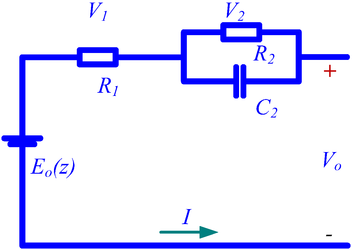
To consider the real-time applications, in this paper the first order RC model, which has been widely used in the industry applications for its simple characteristics, is utilized. Only one RC network and one resistor are used in such a battery model, as shown in
Figure 1.
Figure 1.
The RC model of the Li-ion battery.
Figure 1.
The RC model of the Li-ion battery.
In
Figure 1,
Eo(
z) represents the open circuit voltage (OCV) of the battery,
z is the SOC;
R1 is the resistance of the battery;
R2 is the polarization resistance; while
C2 is used to represent the transient voltage during charging and discharging.
The model is not accurate due to the simplification of the model, the nonlinearity and uncertainty of the real battery. To compensate for the modeling errors, the nonlinear unknown disturbances are added to the battery model:
where
v denotes the disturbances;
w is the measurement errors, and
E1 and
E2 are the coefficients of the disturbances, respectively.
To make the SOC one of the states, the relationship between OCV and SOC are considered firstly and linearized as in a previous study [
20]. The relationship between OCV and SOC could be written as follows:
for the
ith SOC interval (
i − 1)·∆
SOC ≤
SOCi ≤
i·∆
SOC, where ∆
SOC is the SOC interval length. For the
ith SOC interval, the corresponding set (
ai,
bi) can be calculated from the curve and will maintain constant.
So the output equation could be written as follows:
The state function could be rewritten as follows:
where
![Energies 07 05065 i005]()
;
![Energies 07 05065 i006]()
;
![Energies 07 05065 i007]()
;
E = [
E1 E2]
T;
y =
V0 −
bi;
C = [1
ki];
D =
R1;
u =
I.
The discrete state function could be as follows:
where
Ts is the sampling time;
Ad = (1 +
TsA);
Bd =
TsB;
Ed =
TsE;
xk,
uk,
yk,
vk,
wk are the parameters at time index
k respectively.
4. Simulation & Experiment Establishment and Results Analysis
To illustrate the performances of the four model-based SOC estimation methods, a simulation and experimental workbench is established. To verify the model-based SOC estimation methods, the urban dynamometer driving schedule (UDDS) drive cycle is utilized. The UDDS drive cycle is widely used to test vehicle performance, and it is has also been recently introduced to verify the performance of EVs. The UDDS current profile used in this paper is the current demand of the battery pack while the EV is following the speed profile of the traditional UDDS drive cycle. The UDDS current profile is scaled down according to the voltage and the capacity. Several UDDS current profiles are applied to the battery model to obtain the whole SOC range voltage response of the Li-ion battery. To verify the convergency properties of the four model-based methods, the initial SOC is assumed to be unknown, and it is set to be 60% in this study, while the actual SOC of the battery is 100%.
4.1. The Configuration of the Simulation
Since a battery is a strong nonlinear electrochemical system, it is difficult to know its exact properties. To have a clear comparison of the four model-based SOC estimation methods, the simulation workbench is established first.
Firstly, to obtain the model parameters, a 20 Ah EIG Li-ion battery with a Li[NiCoMn]O
2-based cathode and graphite-based anode is tested at room temperature. According to the datasheet of the battery, the maximum charge voltage is 4.15 V and the voltage limit for discharge is 3.0 V. The SOC of the battery is set to be 100% when the battery is fully charged. The battery model parameters are identified with a genetic algorithm to obtain the optimal values. For convenience, the data to obtain the relationship between SOC and OCV are used to identify the battery model. The Least Square Method is introduced to form the objective function while the genetic algorithm is applied to find the optimal set of
R1,
R2 and
C2 for the battery model. The identification results are as follows:
R1 is 0.0027 Ω,
R2 is 0.0042 Ω, and
C2 is 25000
F. The genetic algorithm is utilized to calculate the optimal parameters for the four methods, as shown in
Table 1.
Table 1.
The gains for the four methods.
Table 1.
The gains for the four methods.
| Items | Values |
|---|
| L | [2.1 299.7] |
| H | [0.7 80.0] |
| ρ | [5 40.1] |
| Q | [0.001 17.4] |
| R | [499.8] |
| Kp | [20 9.9] |
| Ki1 | [0.06 10] |
| Ki2 | [2 2] |
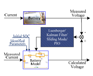
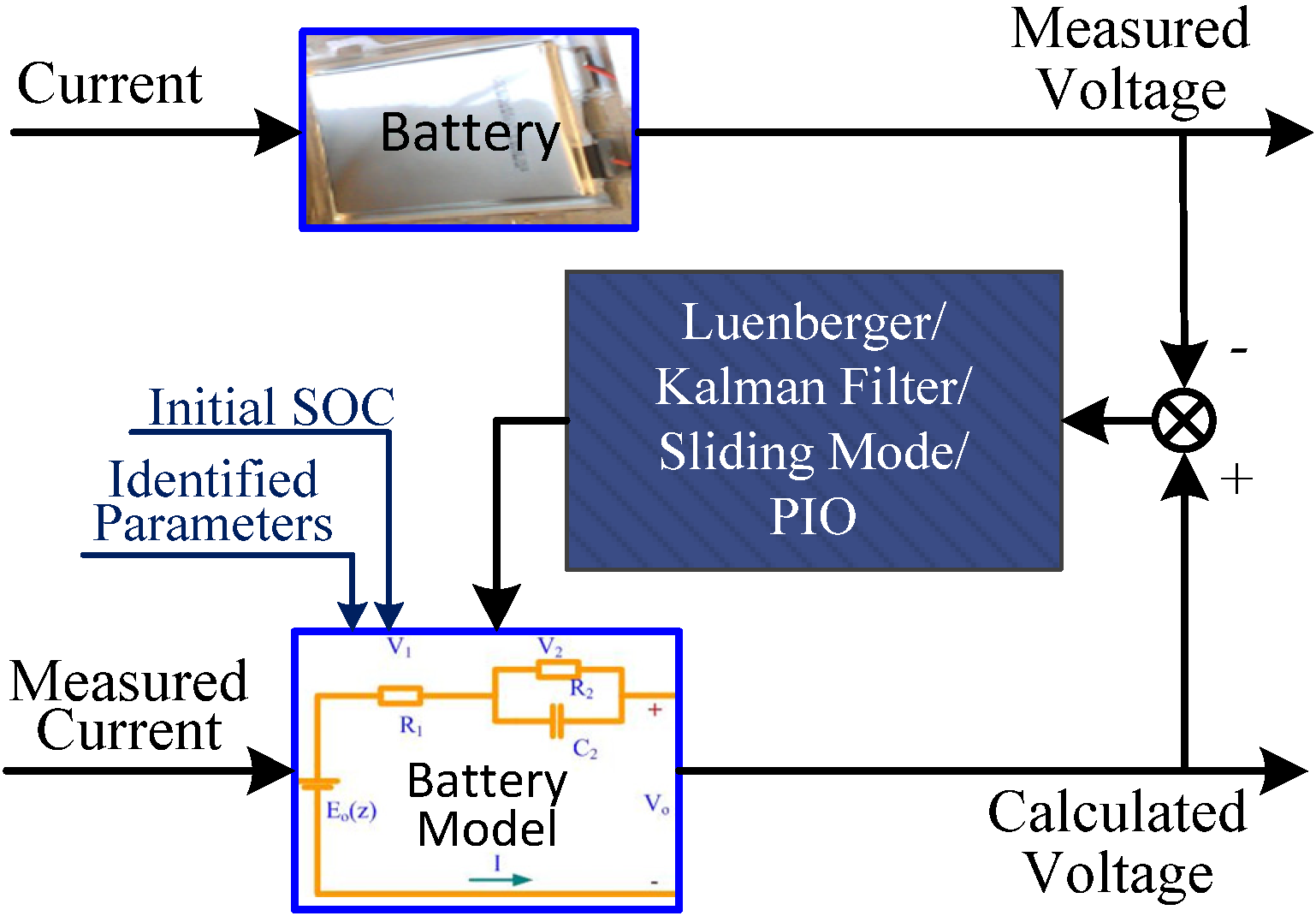
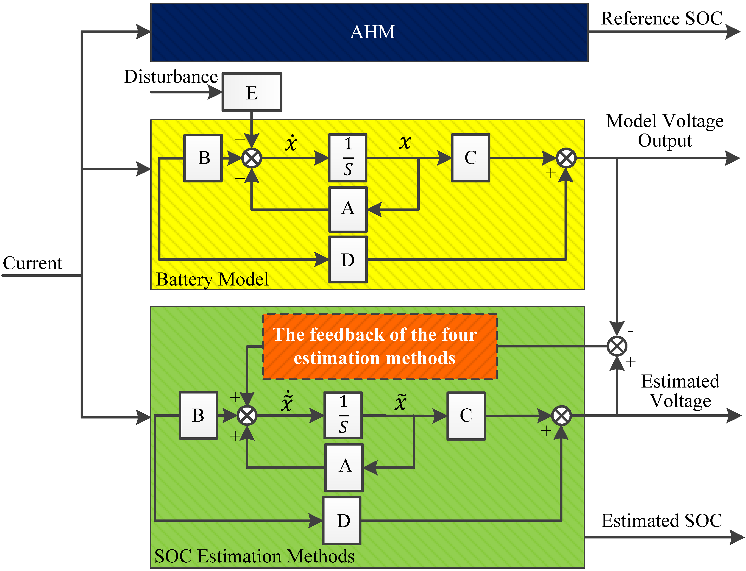
To be clearer, this model is considered to be able to perfectly establish the characteristics of the battery in the simulation. Then this battery model is applied to the simulation both to act as the battery to calculate the model voltage output and also to be applied to the model based SOC estimation method to obtain the estimated voltage and the estimated SOC. The configuration of the simulation is shown as follows in
Figure 3.
Figure 3.
The configuration of the simulation.
Figure 3.
The configuration of the simulation.
The AHM is utilized to calculate the reference SOC since the initial SOC is known and the current sensor could be accurate enough. The current profile, which is a sequence of UDDS current profile, is applied to the battery model and also the four model-based SOC estimation methods. Note that, in this simulation, the battery model used in the four model-based SOC estimation methods are exactly same as the battery model used to calculate the model voltage output.
4.2. Simulation Results and Analysis
To evaluate the performances of the four model-based SOC estimation methods, the battery model without nonlinear disturbance and measurement errors is applied first. In this case, the disturbance
v is set to be zero and the measurement error
w is also set to be zero. The results of such a scenario are shown in
Figure 4.
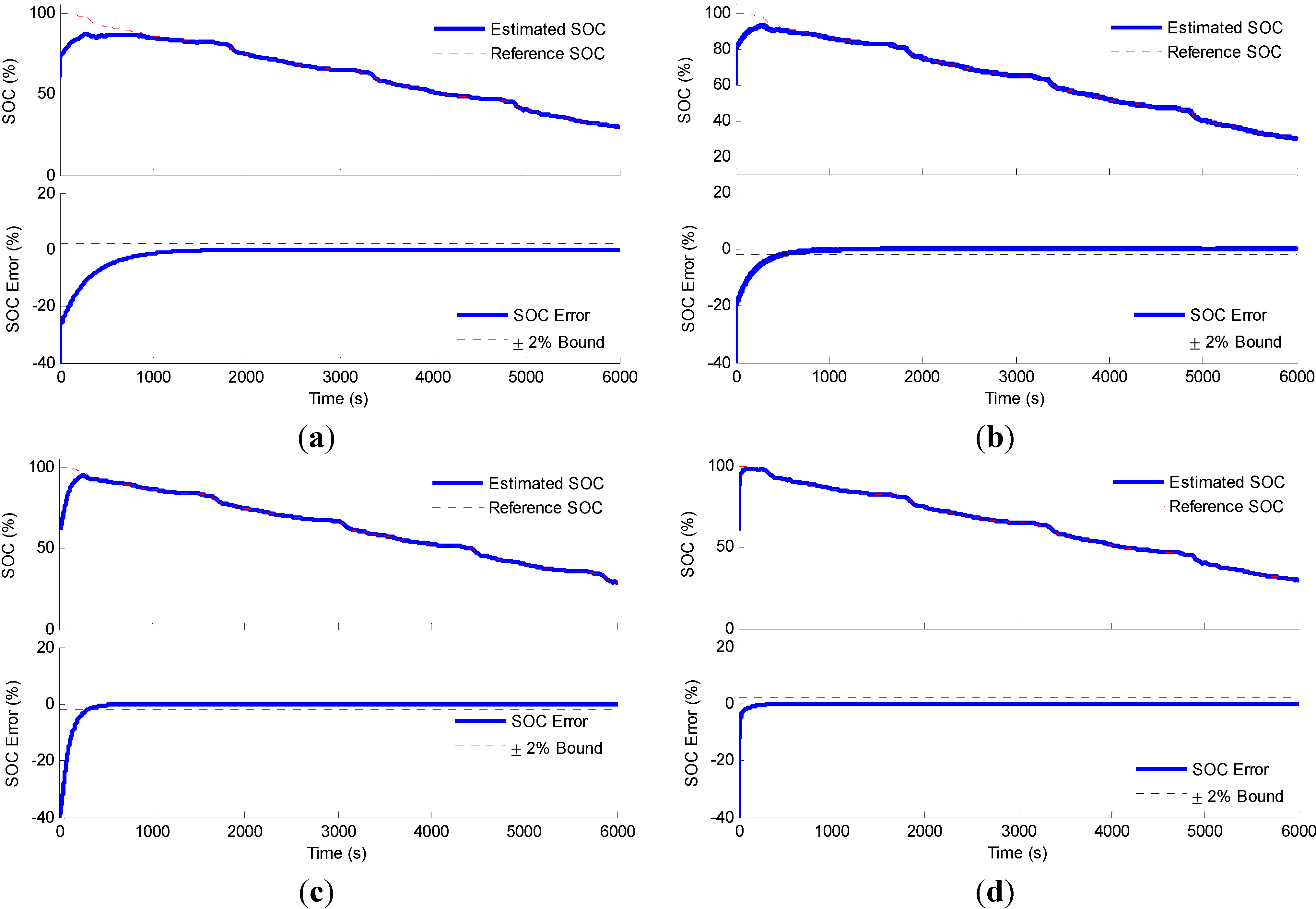
As shown in
Figure 4, the SOC estimation results are good for all four estimation methods. The estimated SOC could converge to the reference SOC quickly and trace the reference SOC with small errors. However, it is clear that the rise times of the convergent processes are quite different. Of the four methods, the Luenberger observer SOC estimation method has the longest rise time, while the PIO SOC estimation method has the shortest, so it could be concluded that the four model-based SOC estimation methods all perform well when no nonlinear disturbance and measurement errors are considered, and the PIO SOC estimation method could achieve the true SOC faster.
Figure 4.
The simulation results of the four SOC estimation methods without disturbance: (a) the Luenberger observer SOC estimation method; (b) the sliding mode observer SOC estimation method; (c) the Kalman filter SOC estimation method; (d) the PIO SOC estimation method.
Figure 4.
The simulation results of the four SOC estimation methods without disturbance: (a) the Luenberger observer SOC estimation method; (b) the sliding mode observer SOC estimation method; (c) the Kalman filter SOC estimation method; (d) the PIO SOC estimation method.
Figure 5.
The simulation results of the four SOC estimation methods with disturbance: (a) the Luenberger observer SOC estimation method; (b) the sliding mode observer SOC estimation method; (c) the Kalman filter SOC estimation method; (d) the PIO SOC estimation method.
Figure 5.
The simulation results of the four SOC estimation methods with disturbance: (a) the Luenberger observer SOC estimation method; (b) the sliding mode observer SOC estimation method; (c) the Kalman filter SOC estimation method; (d) the PIO SOC estimation method.
In the second scenario, the nonlinear disturbance and the measurement error are considered. The disturbance is set to be white noise with 0.2 peak-to-peak voltage in this study. According to the dimensions of the two states, the disturbance coefficients are set to be
E1 = 0.02 and
E2 = 10. The simulation results of the four model-based methods in such a scenario are depicted in
Figure 5.
As shown in the figure, the estimation results for the Luenberger observer SOC estimation method and the sliding mode observer SOC estimation method become worse, and large ripples exist in the estimation errors for these two methods. The SOC error bound turns to be about ±5% for these two methods. However, for the Kalman filter SOC estimation method and the PIO SOC estimation method, the estimation results are almost the same as the first scenario. The SOC error bound is still about ±2%. As far as the rise time of the estimation is considered, the four methods have the same performances as those in the first scenario, respectively. The PIO SOC estimation method has the shortest rise time of the estimation, while the Luenberger observer SOC estimation method has the longest.
According to the analysis of the simulation results of the two scenarios, it could be concluded that the four model-based SOC estimation methods could estimate the SOC of a Li-ion battery efficiently, regardless of whether the nonlinear disturbance is considered or not. Besides, the Kalman filter SOC estimation method and the PIO SOC estimation method outperform the Luenberger observer SOC estimation method and the sliding mode observer SOC estimation method when the nonlinear disturbance is considered in the battery model. Finally, the PIO method has the shortest rise time of the SOC estimation of the battery for both scenarios.
4.3. The Configuration of the Experiment
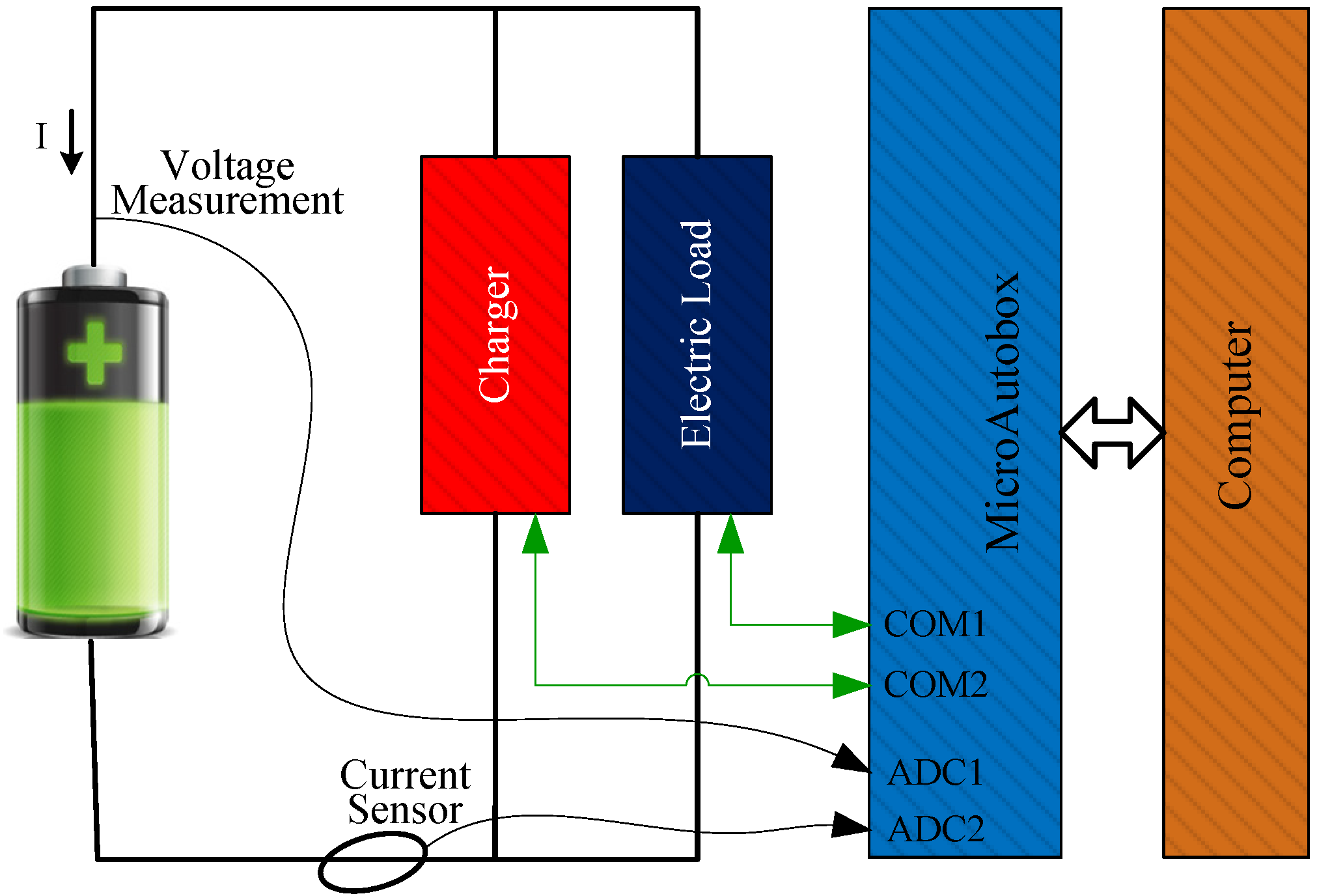
To further illustrate the validity of the analysis above, an experimental battery test bench is established. The configuration of the battery experiment system is illustrated in
Figure 6. It consists of a computer in which a MicroAutobox is installed. A charger and an electric load are connected in parallel with the battery as shown in
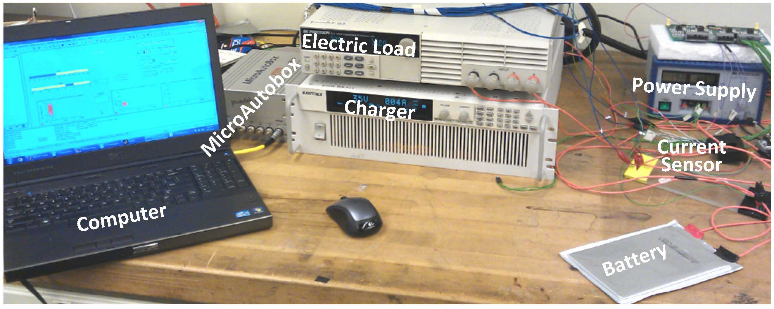
Figure 6. The charger and the electric load are controlled by MicroAutobox according to the signals given by the Simulink models. The current sensor measures the current flowing through the battery and reads it as voltage signals. These voltage signals together with the voltage of the battery are measured by MicroAutobox and fed back to the Simulink models. The battery experiment workbench is depicted in
Figure 7.
Figure 6.
Configuration of the battery experiment system.
Figure 6.
Configuration of the battery experiment system.
Figure 7.
The experimental battery test workbench.
Figure 7.
The experimental battery test workbench.
4.4. Experiment Results and Analysis
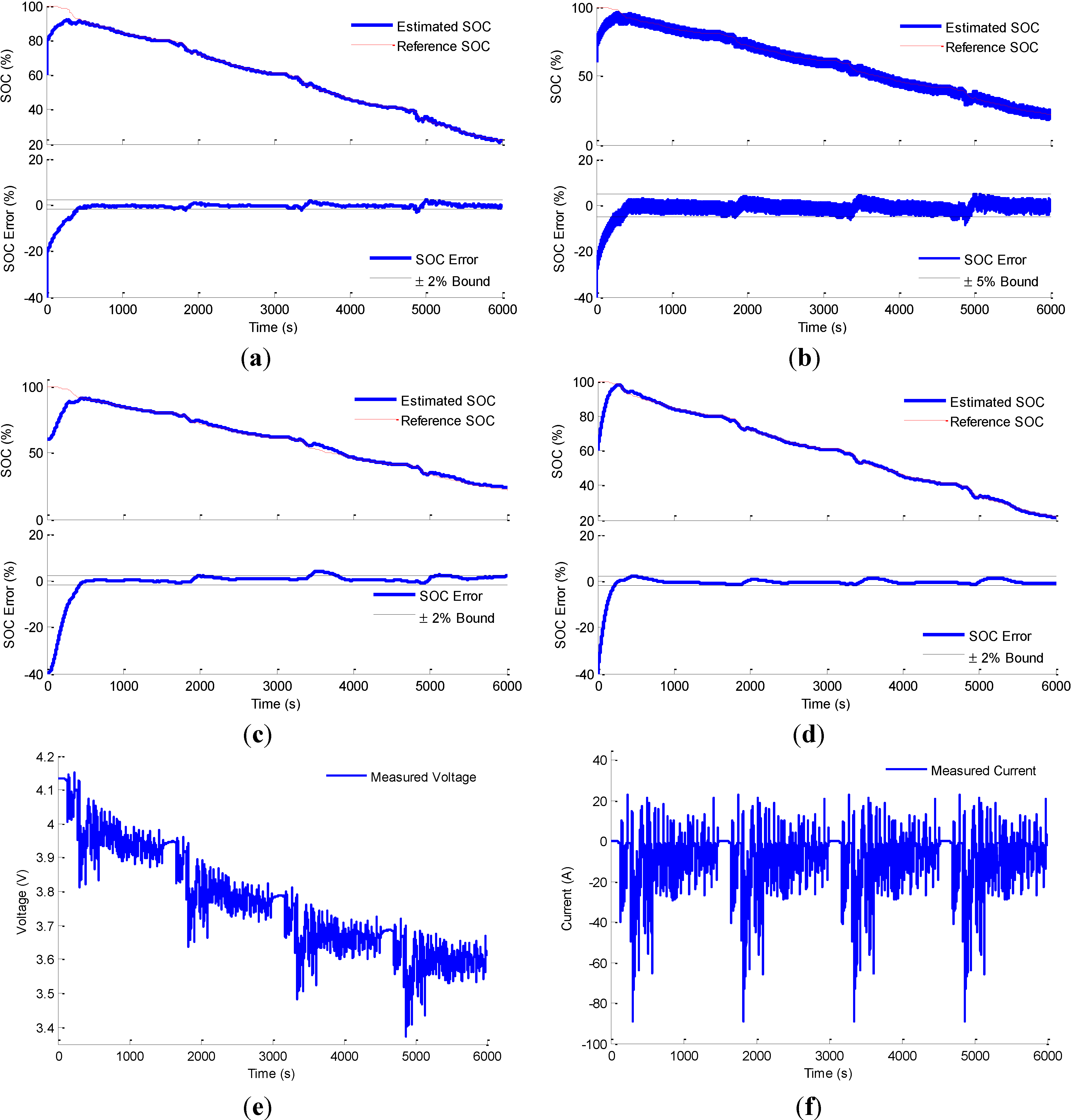
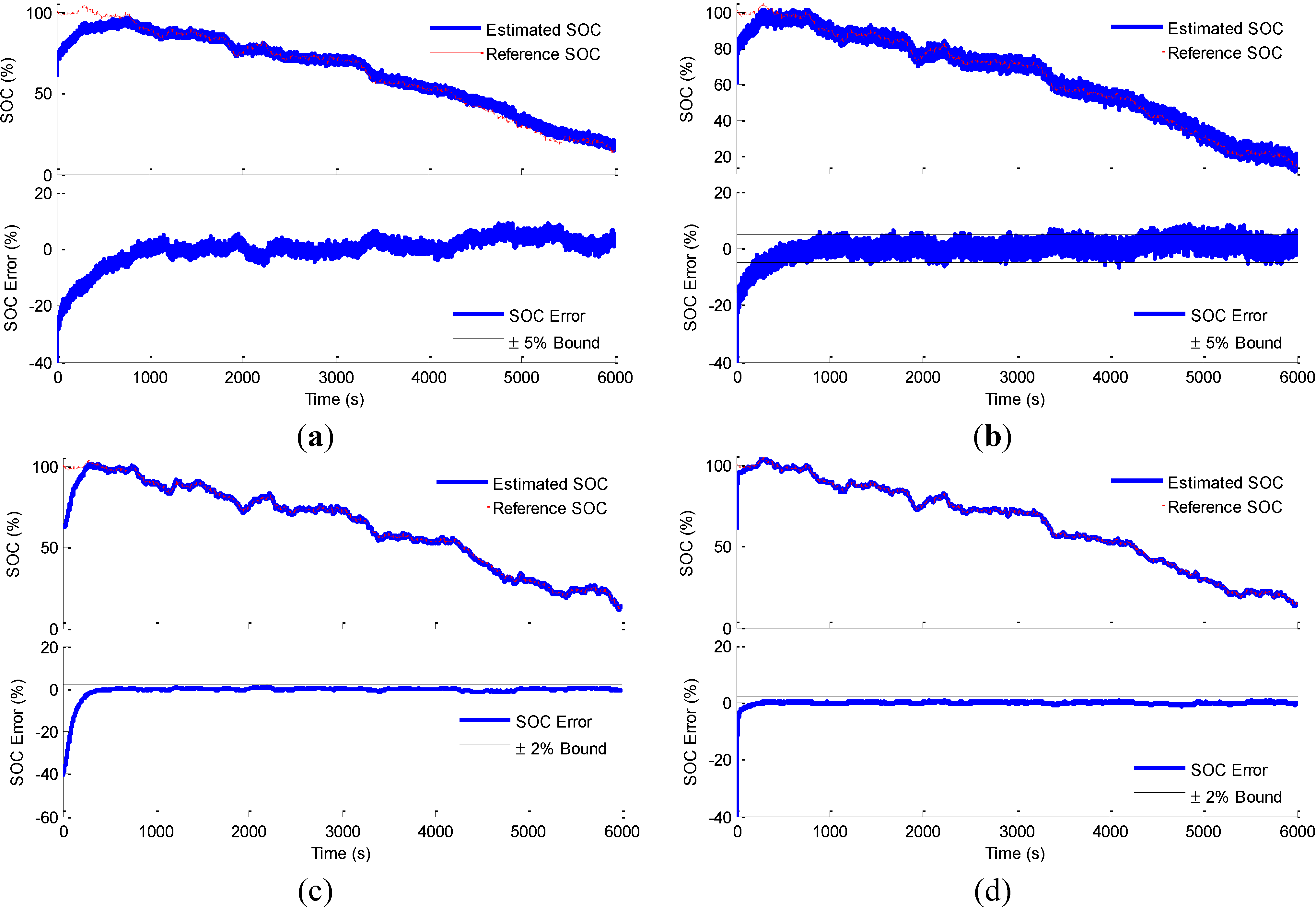
As in the simulation, the initial SOC is also assumed to be unknown and the initial estimated SOC is set to be 60% while the actual SOC is 100% in the experiment. The experimental results are shown as in
Figure 8:
Figure 8.
The experimental results of the four SOC estimation methods: (a) the Luenberger observer SOC estimation method; (b) the sliding mode observer SOC estimation method; (c) the Kalman filter SOC estimation method; (d) The PIO SOC estimation method; (e) the measured voltage; (f) the measured current.
From these figures, it is clear that all the four model based SOC estimation methods could recover the initial SOC error in a short time. After that the estimated SOC could trace the reference SOC with small errors. However, when considered more carefully, several differences could also easily be discovered.
4.4.1. SOC Estimation Error Analysis
According to
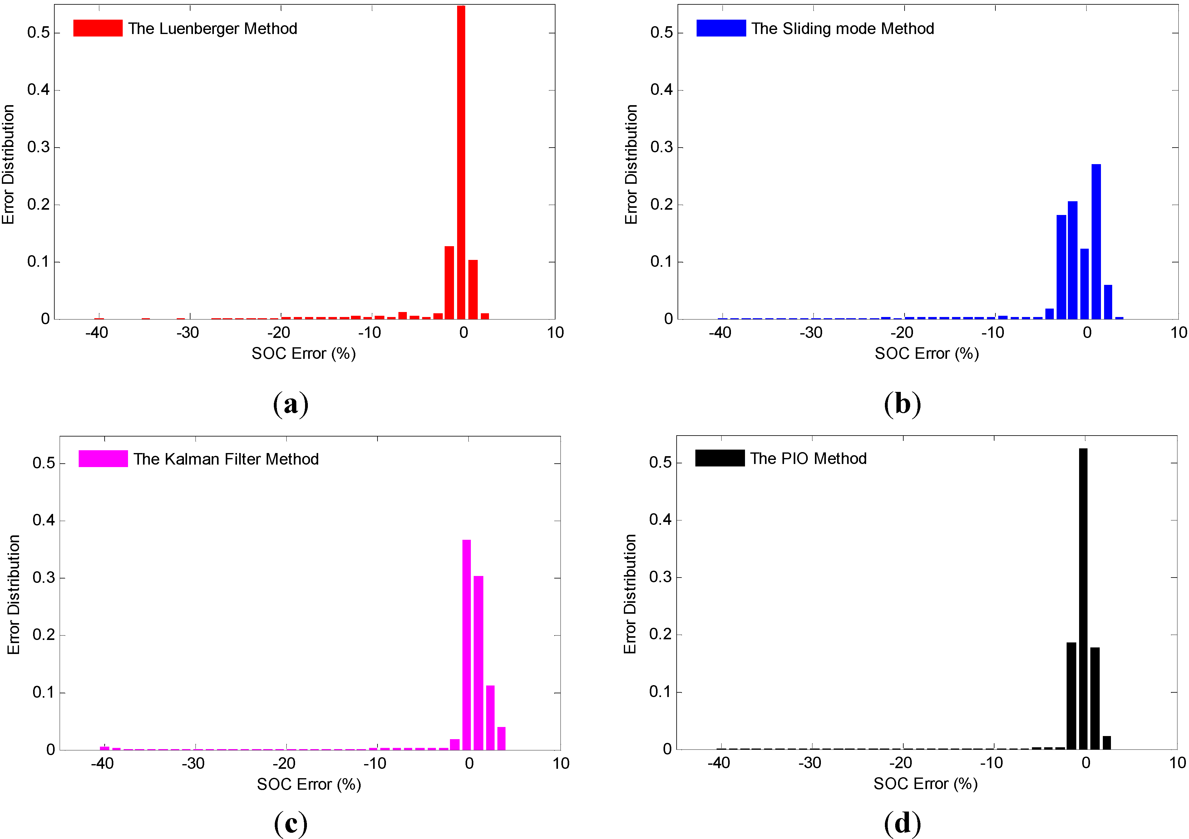
Figure 8, it is obvious that the estimation errors for these four SOC estimation methods are different. To compare the estimation errors, the SOC estimation error distribution of the four methods have been studied in this paper, as shown in
Figure 9. The errors of the sliding mode observer SOC estimation method are more disperse, while those of the other three are distributed more concentrated, which means the sliding mode observer SOC estimation method does not perform as well as the other three methods. This phenomenon is easy to understand considering the chattering problem of the sliding mode observer. Moreover, the PIO SOC estimation method and the Luenberger observer SOC estimation method both have one error distribution peak at zero error, which is more than 0.5. It means that most of the estimation results of these two methods are the same as the true SOC. Besides, when the SOC estimation error range is considered, it is clear from the figure that the estimation errors of the Luenberger observer SOC estimation method, the Kalman filter SOC estimation method and the PIO SOC estimation method are constrained in the ±2% error band, meaning these methods perform better as far as the estimation accuracy is concerned.
Figure 9.
The experimental results of the four SOC estimation methods: (a) the Luenberger observer SOC estimation method; (b) the sliding mode observer SOC estimation method; (c) the Kalman filter SOC estimation method; (d) the PIO SOC estimation method.
Figure 9.
The experimental results of the four SOC estimation methods: (a) the Luenberger observer SOC estimation method; (b) the sliding mode observer SOC estimation method; (c) the Kalman filter SOC estimation method; (d) the PIO SOC estimation method.
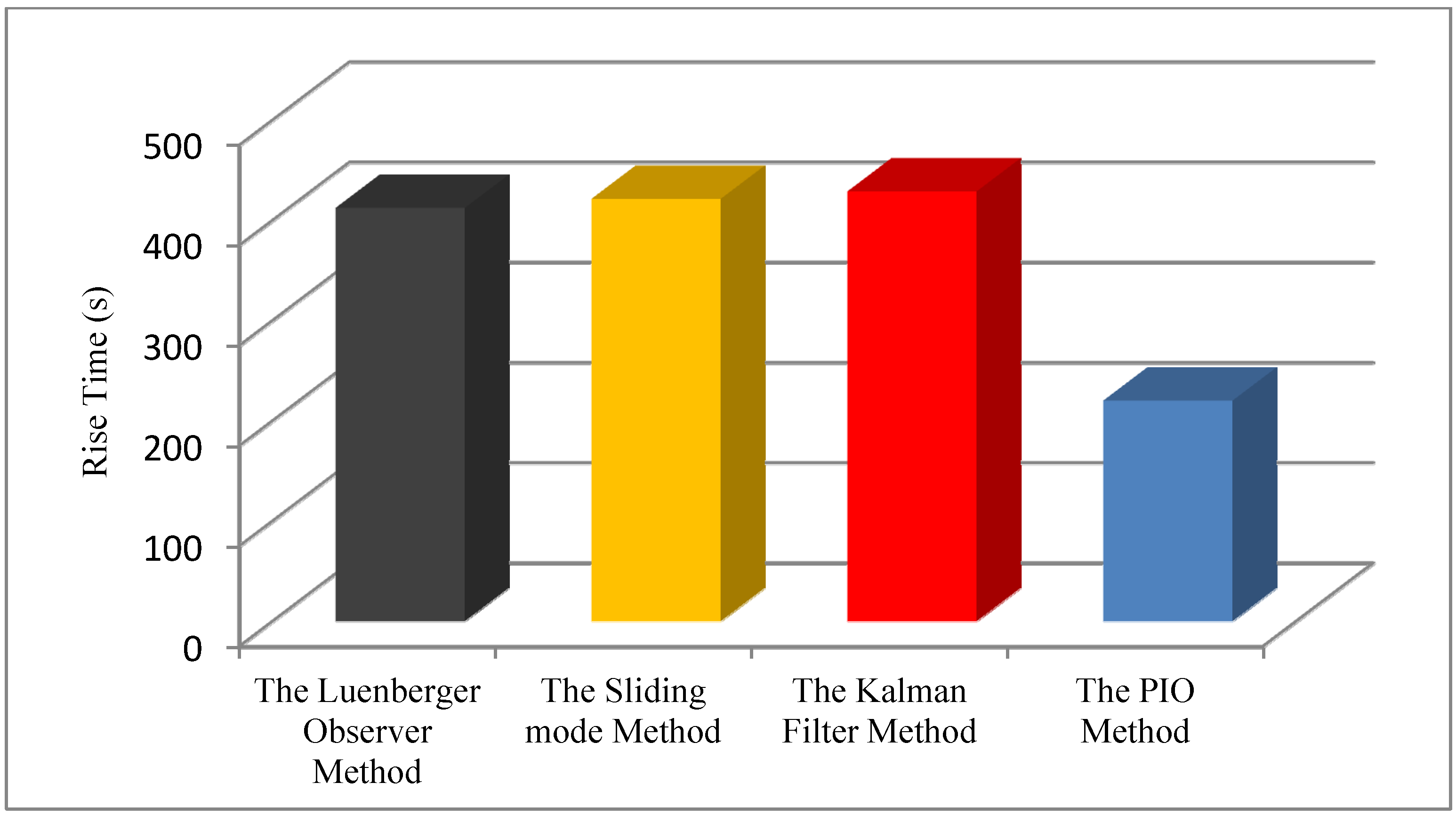
4.4.2. SOC Estimation Rise Time Analysis
The estimation rise time can be used to explain the response speed for the estimation methods. If the estimation rise time of a method is shorter, it means this method could reach the true value of the the estimation faster, which is very important for the SOC estimations, especially for real-time applications, such as EV applications. The estimation rise time of the four SOC estimation methods are shown in
Figure 10. It is clear that the PIO SOC estimation method has the shortest estimation rise time, the Luenberger observer SOC estimation method the second, and the other two methods have longer rise times. It could be concluded that the PIO SOC estimation method performs better in the estimation rise time aspect.
Figure 10.
SOC estimation rise time of the four methods.
Figure 10.
SOC estimation rise time of the four methods.
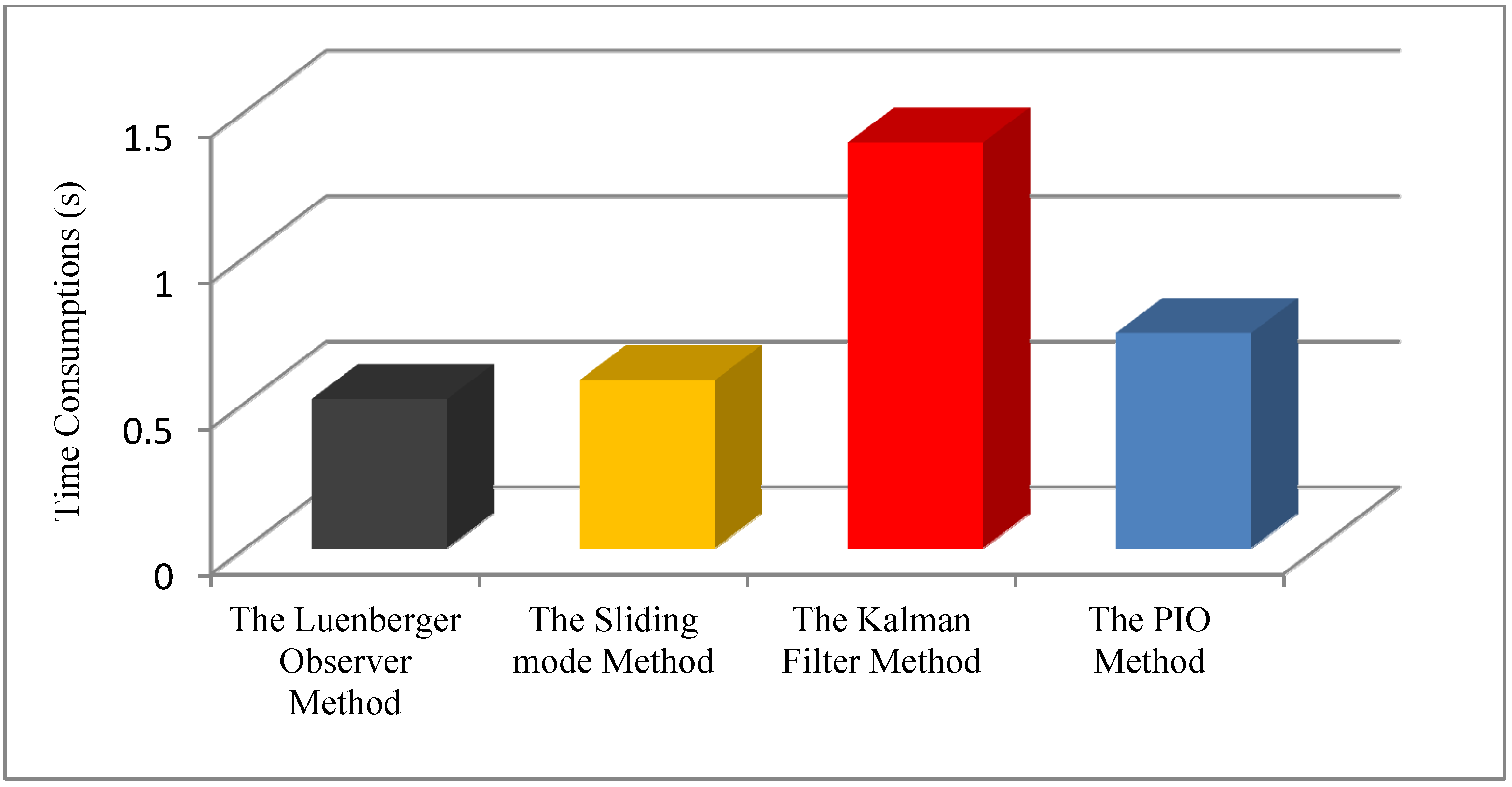
4.4.3. SOC Estimation Time Consumption Analysis
One of the key aspects influencing the practical application of the SOC estimation method is the computation complexity. That is why the AHM is the most popular SOC estimation method in actual industry applications, although the AHM suffers from the initial SOC problem and the accumulative error problem; besides, the model-based SOC estimation methods are much more robust and accurate. To evaluate the computation complexity of the four SOC estimation methods, the following steps are carried out:
Firstly, the voltage and the current of the experiments are recorded.
Secondly, the recorded voltage and the current are applied to the Matlab/Simulink model directly to run the simulation for a certain time period (6000 s) for several times (ten times for example). The computation is performed in a Lenovo ThinkPad laptop with Window 7 operation system, Intel core i5 CPU and 8 GB RAM.
Thirdly, the time consumptions of the simulation for the four SOC estimation methods are recorded.
Finally, the time consumptions for each SOC estimation method are averaged and the average time consumptions for the four SOC estimation methods are shown in
Figure 11.
According to the figure, it is obvious that the Luenberger observer SOC estimation method has the shortest time consumption, the sliding mode observer SOC estimation method the second, the PIO SOC estimation method the third and the Kalman filter SOC estimation method the last. Moreover, the time consumption of the Luenberger observer SOC estimation method and the sliding mode observer SOC estimation method are almost the same, and the time consumption of the PIO SOC estimation method is a little bigger, while the time consumption of the Kalman filter SOC estimation method is much bigger, about twice as large as that of the other three methods.
Figure 11.
The time consumptions of the four methods.
Figure 11.
The time consumptions of the four methods.
4.5. Discussion
The extensions of these four model-based SOC estimation methods may have better performance. Such extensions could be the adaptive Luenberger observer, extended Kalman filter, sigma point Kalman filter, etc. To be more generalized, only the same basic methods are studied and discussed in this paper. The performances of the four methods are much different due to their own particular characteristics, which have been verified by simulations and experiments. The differences in the time consumptions were obvious: the feedback coefficient of the Luenberger observer SOC estimation method is the Luenberger gain which is constant, while the Kalman filter SOC estimation method has to calculate the Kalman gain through Equations (9) to (13), where complex covariances have to be calculated, leading to a longer calculation time. The PIO SOC estimation method takes advantage of the integral of the voltage errors and thus the estimation errors could be smaller and the rise time could be shorter, while the time consumption would be longer than Luenberger SOC estimation method for the added integral part, but shorter than the covariance computation of the Kalman filter SOC estimation method.
5. Conclusions
In this paper four model-based SOC estimation methods including the Luenberger observer, the Kalman filter, the sliding mode observer and the PIO have been evaluated to estimate the SOC of Li-ion batteries. The first order RC model with nonlinear disturbance has been represented to describe the battery electrical behavior. The basic theories of the four methods have been studied and analyzed. Their performances were evaluated through simulations and experiments. The simulations consisted of two scenarios, with and without a nonlinear disturbance. Different aspects of the SOC estimation have been evaluated through the experiments, such as the estimation error distribution, the estimation rise time, the estimation time consumption, etc. Simulation and experimental results showed that the four model-based SOC estimation methods performed well but with different estimation rise times, in which the PIO SOC estimation method performed best. Besides, the Kalman filter SOC estimation method and the PIO SOC estimation method were better than the Luenberger observer SOC estimation method and the sliding mode observer SOC estimation method to attenuate the nonlinear disturbance. The estimation errors were in the ±2% error bound for the former three methods, compared to ±5% for the latter one. The Luenberger observer SOC estimation method, the sliding mode observer SOC estimation method and the PIO SOC estimation method performed better than the Kalman filter SOC estimation method in the estimation time consumption.
To sum up, the PIO SOC estimation method and the Kalman filter SOC estimation method are more suitable for actual applications involving complex environments with unknown disturbances, such as EV applications. If the actual application highly requires real-time computation, the PIO SOC estimation method is better relatively for the time consumption aspect.


 ;
;  ;
;  ; E = [E1 E2]T; y = V0 − bi; C = [1 ki]; D = R1; u = I.


 is the a priori state estimation at step k;
  is the posterior state estimation; Pk is the error covariance of the state estimation; Q is the covariance of the disturbance v; R is the covariance of the measurement error w.


