Application of the NOx Reaction Model for Development of Low-NOx Combustion Technology for Pulverized Coals by Using the Gas Phase Stoichiometric Ratio Index

Abstract
:1. Introduction
2. Results and Discussion
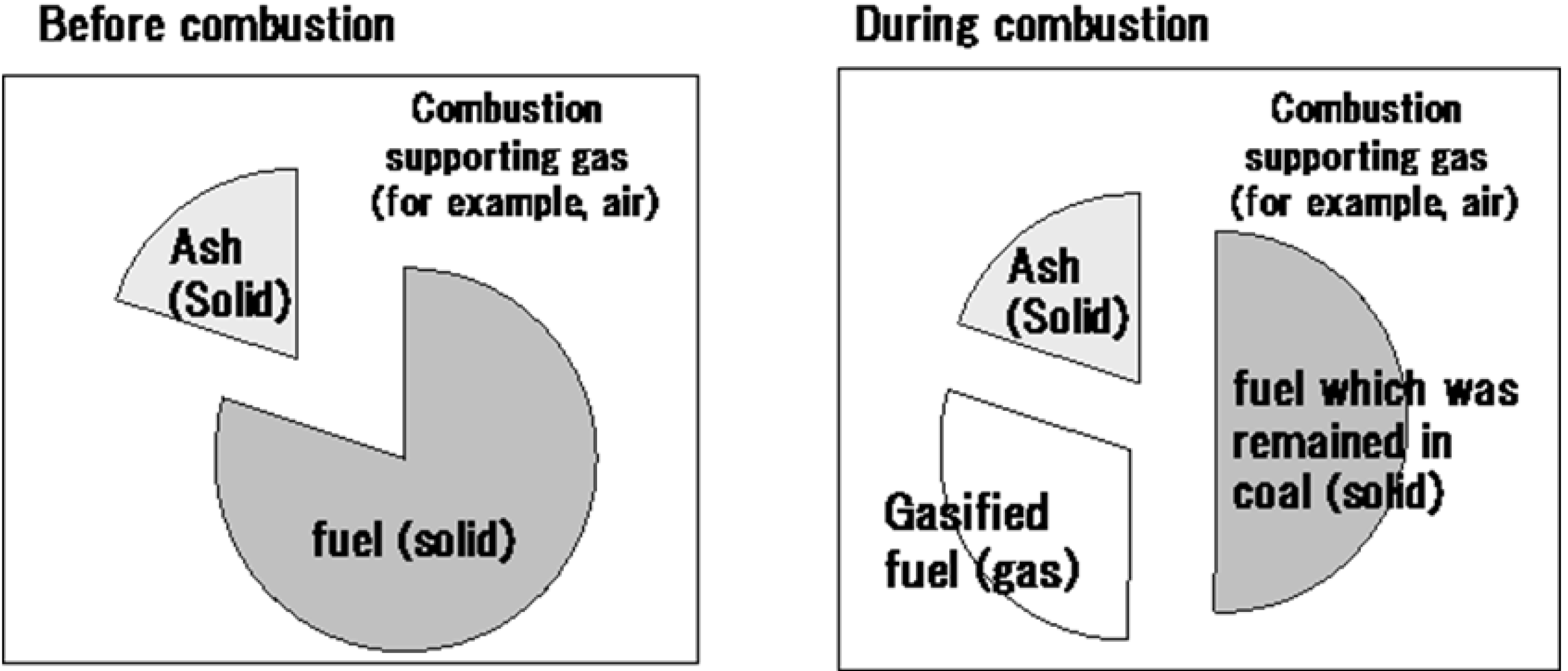
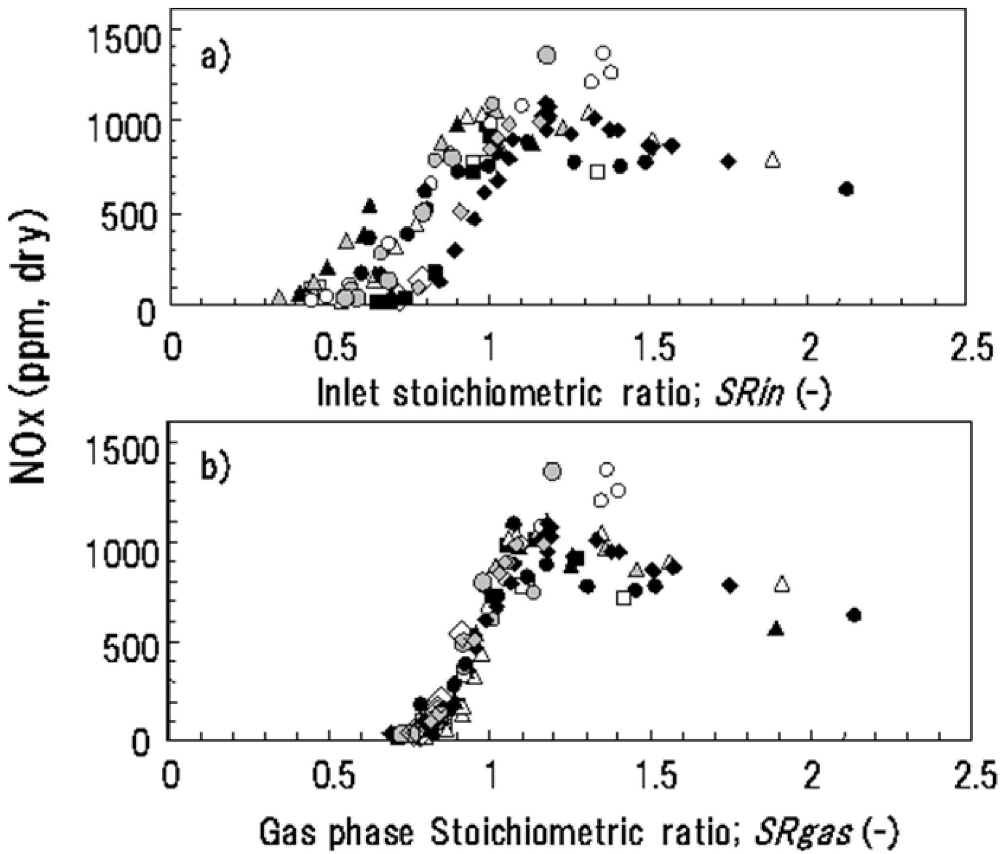
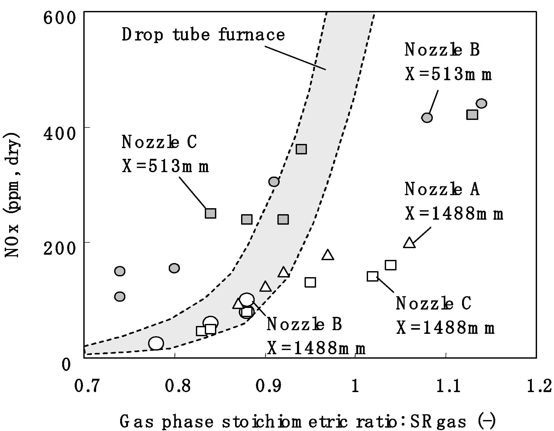
2.1. The Relationship between Gas Phase Stoichiometric Ratio, SRgas, and NOx

| Symbol | Coal | Temp. (K) | Combustion Supporting Gas | Inlet O2 (vol%) | Diameter (μm) | L (mm) |
|---|---|---|---|---|---|---|
| ◆ | A | 1673 | air | 21 | 40 | 800 |
| B | 1573 | air | 21 | 59 | 800 | |
| ■ | C | 1573 | air | 21 | 17 | 800 |
| △ | D | 1573 | air | 21 | 37 | 800 |
| ▲ | D | 1573 | air | 21 | 37 | 200–400 |
| D | 1673 | CO2/O2 | 21 | 37 | 800 | |
| ○ | F | 1673 | air | 21 | 45 | 800 |
| ● | F | 1673 | N2/O2 | 16 | 45 | 800 |
| F | 1673 | N2/O2 | 24 | 45 | 800 | |
| □ | J | 1673 | air | 21 | 16 | 800 |
| ◇ | K | 1873 | air | 21 | 45 | 800 |
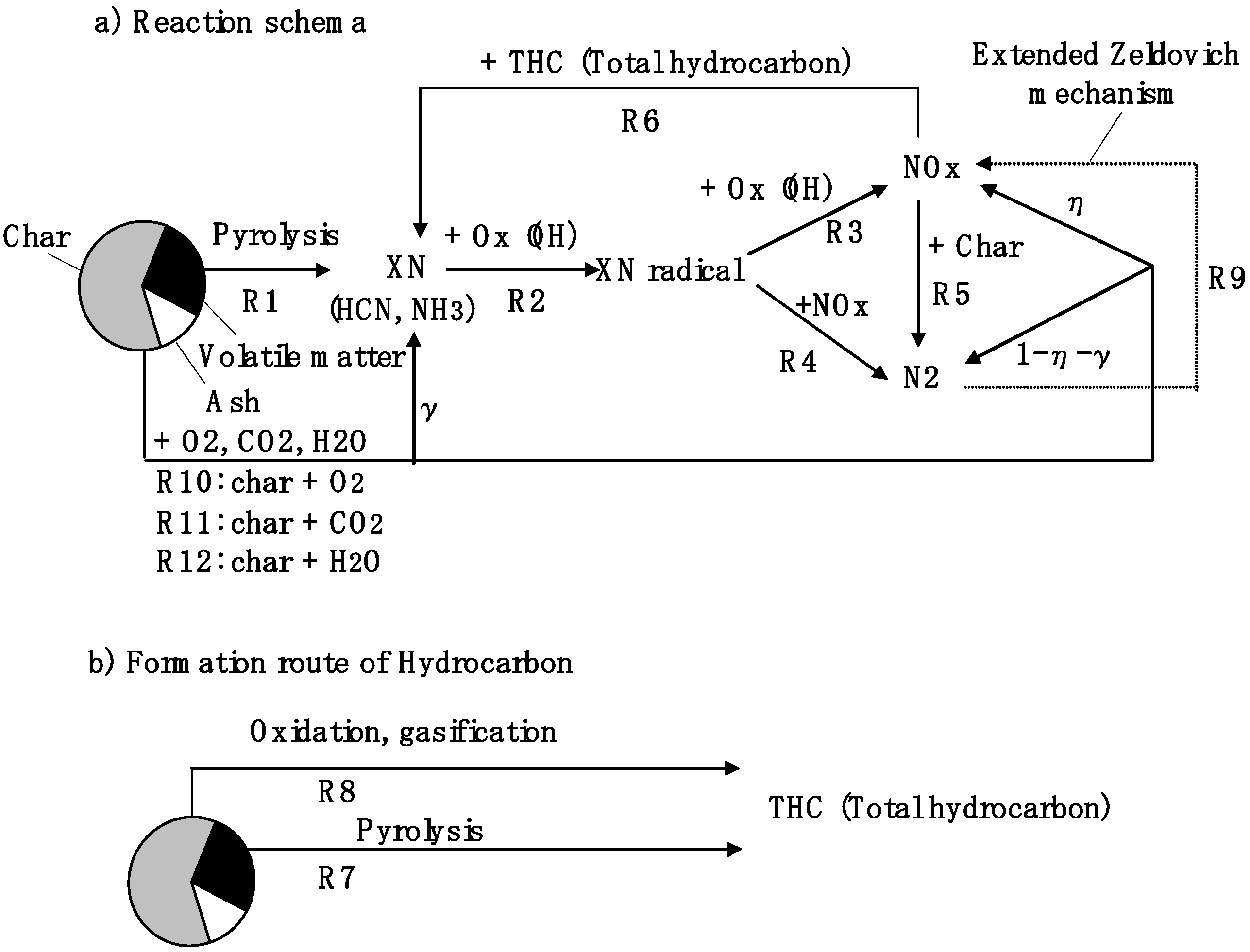
2.2. Reaction Model


| No. | Reaction | Form |
|---|---|---|
| R1 | Pyrolysis of volatile matter | See Ref. 20 |
| R2 | XN + OH → XNradical | d[XN]/dt = kR2 exp(−ER2/RT) [XN][OH] |
| R3 | XNradical + OH → NOx | d[XNradical]/dt = kR3 exp(−ER3/RT) [XNradical][OH] |
| R4 | XNradical + NOx → N2 | d[XNradical]/dt = kR4 exp(−ER4/RT) [XNradical][NOx] |
| R5 | NOx + Char → N2 | d[NOx]/dt = kR5 exp(−ER5/RT) S' [NOx]n |
| R6 | NOx + THC → N2 + XN | d[NOx]/dt = kR6 exp(−ER6/RT) [NOx][THC] |
| R9 | Extended Zelvovich mechnism | |
| R10 | C + 0.5O2 → CO | dC/dt = kR10 exp(−ER10/RT) S PO2n |
| R11 | C + CO2 → 2CO | dC/dt = kR11 exp(−ER11/RT) S PCO2n |
| R12 | C + H2O → CO + H2 | dC/dt = kR12 exp(−ER12/RT) S PH2On |
| Estimation of Total Hydrocarbon concentration | XTHC = kTHC((H/C)VM R1 + (H/C)char (R10 + R11 + R12)) (1/SRgas)n exp(−ETHC/RT) |
| Reaction | k | E | n |
|---|---|---|---|
| R5 (mol-NO/m3-total gas s) | kR5 = 0.865 + 10.8 XO2 ((m3/mol)0.9 m s−1) | 28 (kJ/mol) | 0.9 |
| R10 (kg-carbon/kg-total gas s) | 7.99 × 10⁻⁴ (kg/m2 Pa s) | 66 (kJ/mol) | 1 |
| R11 (kg-carbon/kg-total gas s) | 1.46 × 10⁻³ (kg/m2 Pa s) | 154 (kJ/mol) | 1 |
| R12 (kg-carbon/kg-total gas s) | 1.46 × 10⁻² (kg/m2 Pa s) | 154 (kJ/mol) | 1 |
| XTHC (mole fraction, as CH4) | 3.15 × 10⁻⁹ (kg-total gas s/kg-carbon) | −195 (kJ/mol) | 13 |
| Reaction | k | E |
|---|---|---|
| R2 (mol/m3 s) | 4.6899 × 10⁶ (m3/mol s) | 43.2 (kJ/mol) |
| R3 (mol/m3 s) | 5.35 × 10¹⁰ (m3/mol s) | 168 (kJ/mol) |
| R4 (mol/m3 s) | 1.52 × 10¹² (m3/mol s) | 251 (kJ/mol) |
| R5 (mol/m3 s) | 1.64 × 10¹⁵ (m3/mol s) | 372 (kJ/mol) |
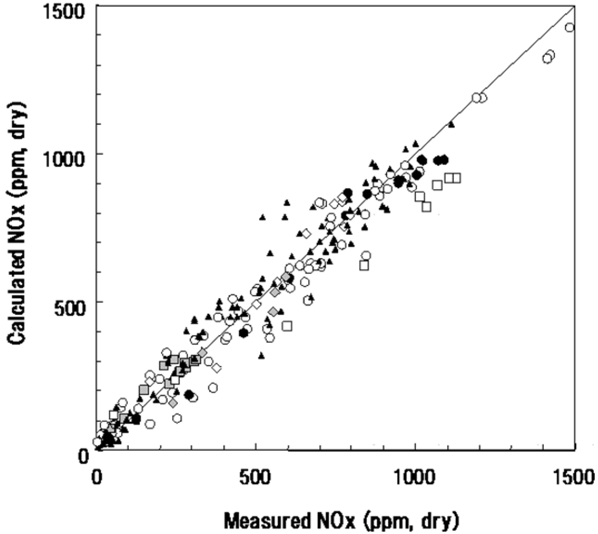
2.3. Calculated Results


| Symbol | Coal | Temp. (K) | Inlet O2 (vol%) | Inlet NOx (ppm) | Diameter (μm) | L (mm) |
|---|---|---|---|---|---|---|
| ● | A | 1673 | 21 | 0 | 40 | 800 |
| ▲ | B | 1173–1773 | 21 | 0 | 23–155 | 400–800 |
| □ | E | 1673 | 21 | 0 | 22 | 800 |
| ○ | F | 1173–1673 | 16–24 | 0–1000 | 14–45 | 800 |
| ◇ | G | 1673 | 21 | 0 | 40 | 800 |
| H | 1673 | 21 | 0 | 33 | 800 | |
| I | 1673 | 21 | 0 | 35 | 800 |

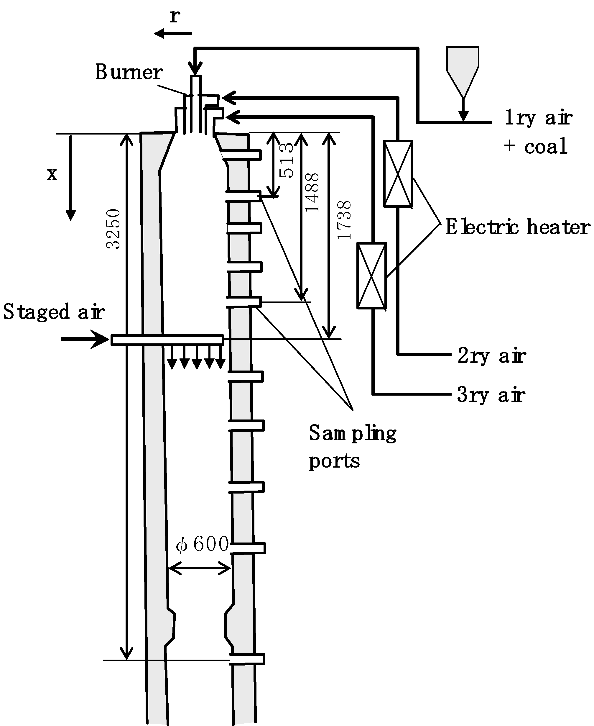
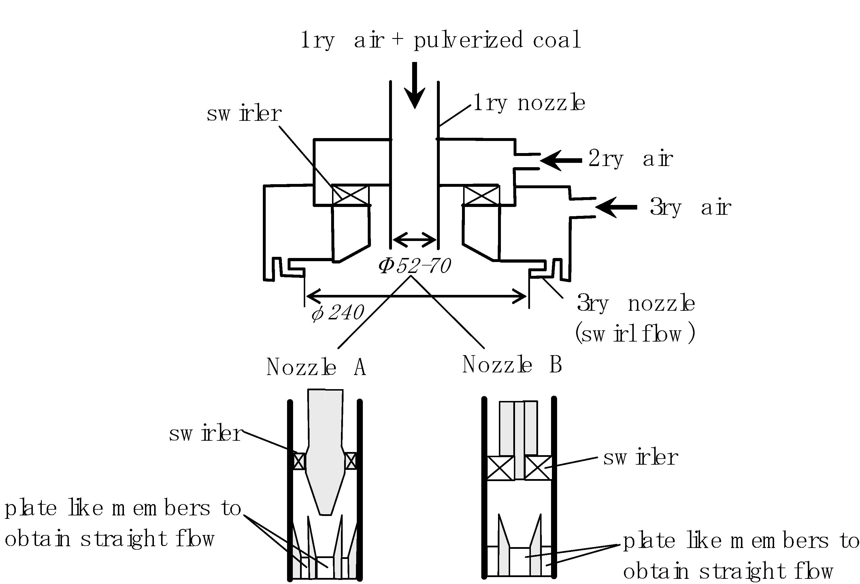
2.4. Application of SRgas to Low-NOx-Combustion Technology Development in the Air Combustion Experiment


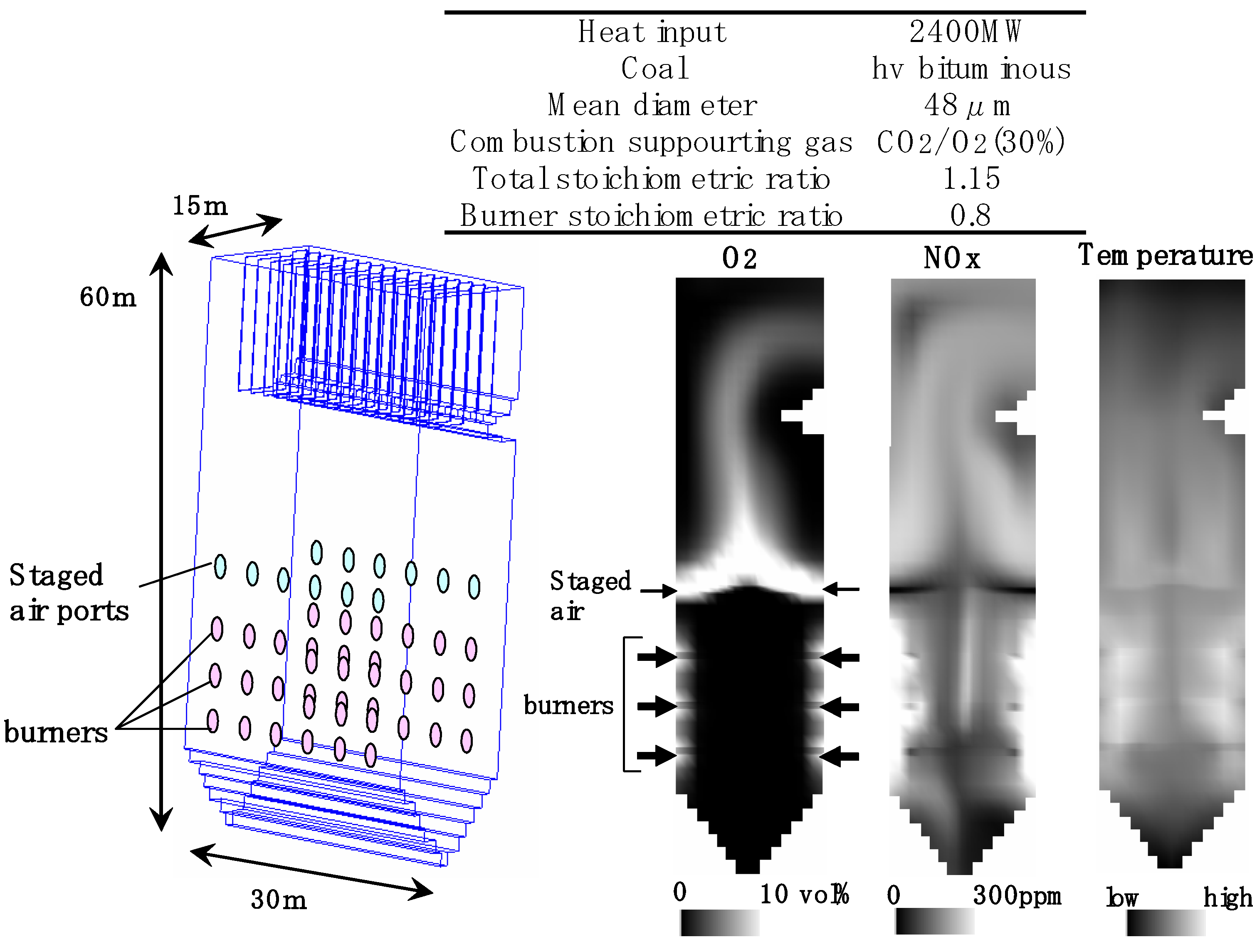
2.4. Application of SRgas to Low-NOx-Combustion Technology Development in the Oxyfuel Combustion Calculation


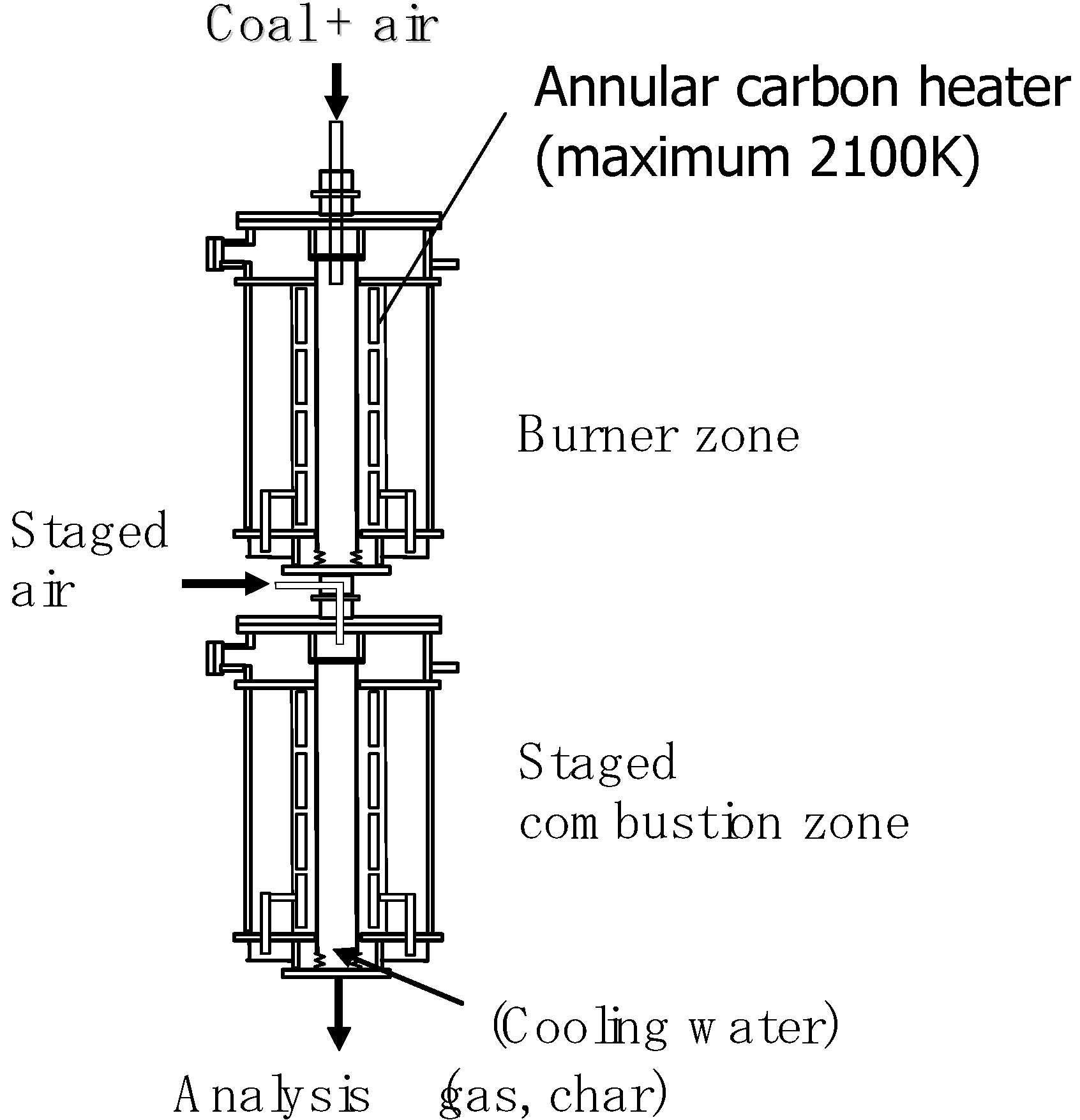
3. Experimental Section

| Name | Coal | Area | VM | Ash | Fuel Ratio | C | H | N | O | S | Mean Diameter (μm) |
|---|---|---|---|---|---|---|---|---|---|---|---|
| (wt%, dry) | (wt%, dry, ash-free) | ||||||||||
| A | sub-bituminous | Asia | 41.6 | 15.7 | 1.0 | 74.2 | 6.2 | 1.8 | 17.1 | 0.8 | 40 |
| B | sub-bituminous | Noth America | 43.6 | 6.2 | 1.2 | 69.1 | 5.4 | 1.1 | 23.8 | 0.6 | 23, 59, 155 |
| C | hv-bituminous | Noth America | 36.3 | 18.7 | 1.2 | 76.7 | 5.5 | 1.6 | 12.6 | 3.6 | 17 |
| D | hv-bituminous | Oceania | 31.1 | 14.9 | 1.7 | 81.1 | 5.8 | 1.8 | 10.7 | 0.7 | 37 |
| E | hv-bituminous | Oceania | 27.6 | 10.2 | 2.3 | 81.5 | 4.6 | 1.8 | 11.7 | 0.5 | 22 |
| F | hv-bituminous | Oceania | 26.3 | 12.8 | 2.3 | 84.9 | 5.5 | 1.9 | 7.2 | 0.5 | 14, 45 |
| G | mv-bituminous | Oceania | 20.6 | 8.5 | 3.4 | 87.6 | 4.7 | 2.1 | 4.8 | 0.8 | 40 |
| H | petroleum coke | Noth America | 11.8 | 2.4 | 7.3 | 88.7 | 3.3 | 1.5 | 1.3 | 5.4 | 33 |
| I | anthracite | Asia | 8.9 | 13.3 | 8.7 | 92.3 | 1.7 | 0.5 | 5.2 | 0.3 | 35 |
| J | anthracite | Asia | 7.6 | 25.3 | 8.8 | 90.7 | 3.5 | 1.4 | 3.5 | 1 | 16 |
| K | hv-bituminous | Oceania | 32.5 | 14.3 | 1.6 | 83.4 | 5.4 | 1.9 | 8.8 | 0.5 | 45 |
4. Conclusions
- (1)
- Gas phase stoichiometric ratio (SRgas) was defined as:where the amount of gasified fuel was defined as the amount of fuel which had been released to the gas phase by pyrolysis, oxidation and gasification reactions. SRgas was determined to be a good index to consider the gas phase reaction mechanism in fuel-rich pulverized coal flames.SRgas = amount of fuel required for stoichiometric combustion/amount of gasified fuel
- (2)
- We applied the SRgas index to develop a NOx reaction model. The key feature was that the concentration of hydrocarbons was estimated as a function of SRgas. Calculated NOx characteristics reproduced the experimental results obtained from a drop-tube furnace. The model was verified for various coals, particle diameters, reaction times and initial oxygen concentrations.
- (3)
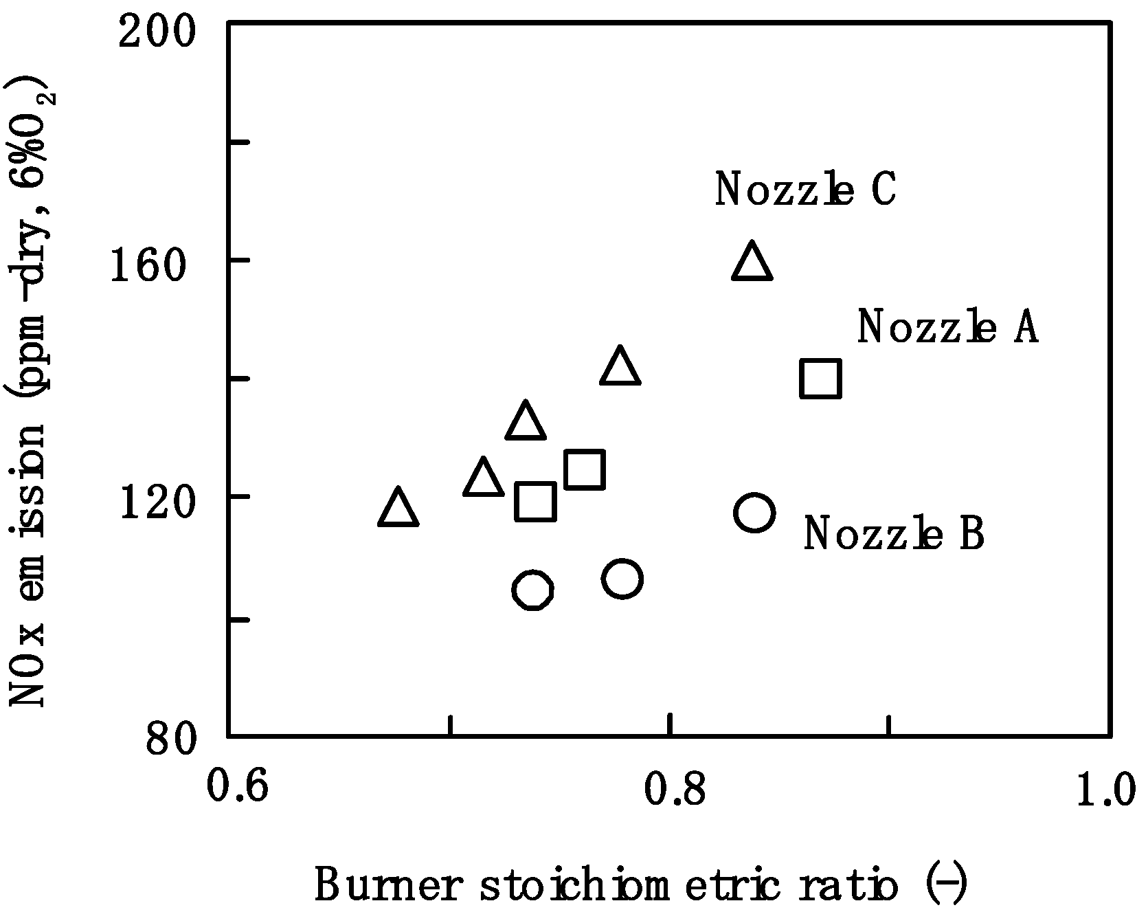
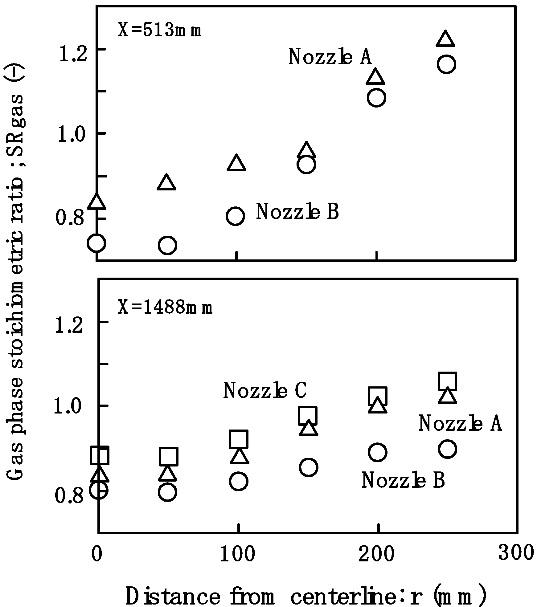
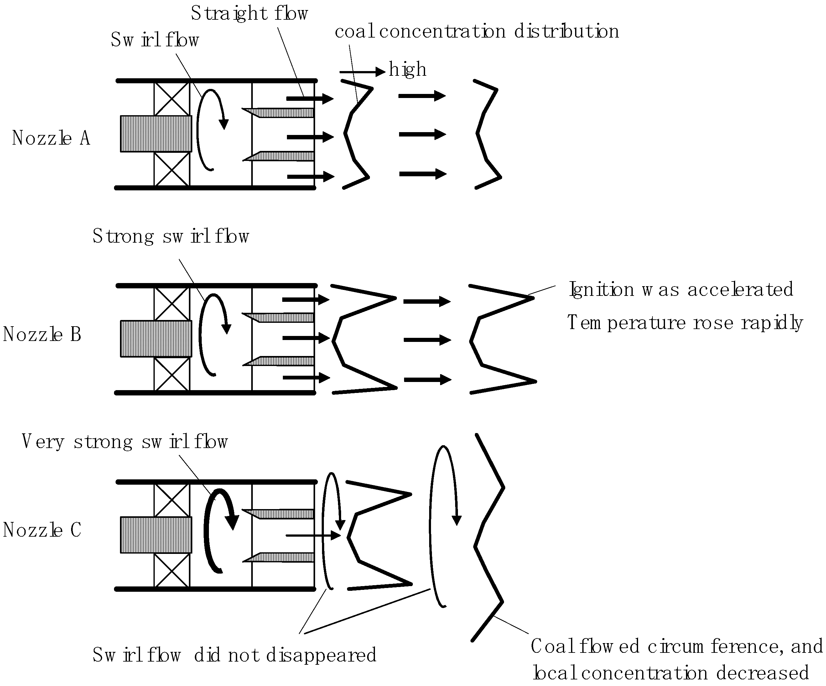
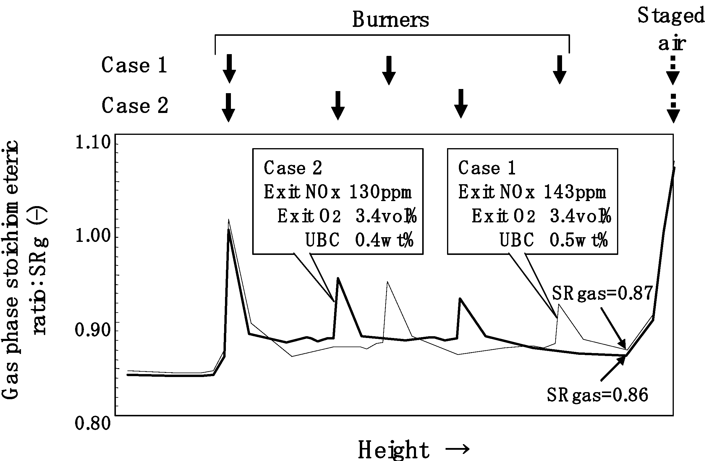
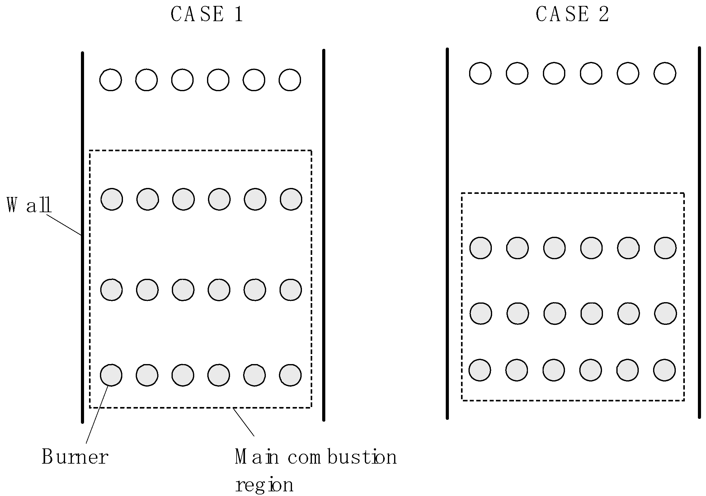
- We applied SRgas to develop a low-NOx-combustion system. When using staged combustion, it was important to reduce the SRgas value as much as possible, just before mixing with staged air. When we adopted the burner structure and the placement at which SRgas became the lowest, the NOx emission of the furnace became the lowest as well.
Nomenclature
| E | activation energy (J/mol) |
| k | frequency factor |
| L | distance between the burner nozzle and sampling port (mm) |
| n | constant |
| [NOx] | concentration of NOx (mol/m3) |
| [OH] | concentration of OH (mol/m3) |
| [OHeq] | equilibrium concentration of OH (mol/m3) |
| Ox(OH) | oxidative species, such as OH |
| PO2 | partial pressure of oxygen (Pa) |
| PCO2 | partial pressure of carbon dioxide (Pa) |
| PH2O | partial pressure of water (Pa) |
| R | gas constant, 8.314 J/K mol |
| S | total surface area of coal or char (m2/kg-total gas) |
| S’ | total surface area of coal or char (m2/m3-total gas) |
| SRin | inlet stoichiometric ratio |
| SRgas | gas phase stoichiometric ratio |
| T | gas temperature (K) |
| X | axial location (mm) |
| XCO | mole fraction of carbon monoxide |
| XCH4 | mole fraction of methane |
| XH2 | mole fraction of hydrogen |
| XO2 | mole fraction of oxygen |
| XO2 0 | mole fraction of oxygen in combustion supporting gas |
| XN (NH3, HCN) | nitrogenous species |
| [XN] | concentration of XN (mol/m3) |
| [XNradical] | concentration of XNradical (mol/m3) |
| XTHC | mole fraction of total hydrocarbons |
| XTR | mole fraction of tracer |
| XTR 0 | mole fraction of tracer in combustion supporting gas |
References
- Azuhata, A.; Narato, K.; Kobayashi, H.; Arashi, N.; Morita, S.; Masai, T. A study of gas composition profiles for low NOx pulverized coal combustion and burner scale-up. Proc. Combust. Inst. 1986, 21, 1199–1206. [Google Scholar] [CrossRef]
- Förtsch, D.; Kluger, F.; Schnell, U.; Spliethoff, H.; Hein, K.R.G. A kinetic model for the prediction of NO emission from staged combustion of pulverized coal. Proc. Combust. Inst. 1998, 27, 3037–3044. [Google Scholar] [CrossRef]
- Cancès, J.; Commandrè, J.M.; Salvador, S.; Dagaut, P. NO reduction capacity of four major solid fuels in reburning conditions-Experiments and modeling. Fuel 2008, 87, 274–289. [Google Scholar] [CrossRef]
- Tsumura, T.; Morita, S.; Kiyama, K.; Kobayashi, H.; Yoshizako, H. Development of Extremely Low NOx Pulverized Coal Burners by Using the Concept of “In-Flame NOx Reduction”. In Proceedings of JSME-ASME International Conference on Power Engineering-93, Tokyo, Japan, 12–16 September 1993; Volume 2, pp. 325–330.
- Taniguchi, M.; Kamikawa, K.; Okazaki, T.; Yamamoto, K.; Orita, H. A role of hydrocarbon reaction for NOx formation and reduction in fuel-rich pulverized coal combustion. Combust. Flame 2010, 157, 1456–1466. [Google Scholar] [CrossRef]
- Williams, A.; Pourkashanian, M.; Bysh, P.; Norman, J. Modeling of coal combustion in low-NOx p.f. flames. Fuel 1994, 73, 1006–1019. [Google Scholar] [CrossRef]
- Yamamoto, K.; Fukuchi, T.; Chaki, M.; Shimogori, Y.; Matsuda, J. Development of Computer Program for Combustion Analysis in Pulverized Coal Fired Boilers. Hitachi Rev. 2000, 49, 4976–4980. [Google Scholar]
- Yamamoto, K.; Taniguchi, M.; Kobayashi, H.; Sakata, T.; Kudo, K. Validation of coal combustion model by using experimental data of utility boilers. JSME Int. J. Ser. B 2005, 48, 571–578. [Google Scholar] [CrossRef]
- Le Bris, T.; Cadavid, F.; Caillat, S.; Pietrzyk, S.; Blondin, B.; Baudoin, B. Coal combustion modeling of large power plant, for NOx abatement. Fuel 2007, 86, 2213–2220. [Google Scholar]
- Man, C.K.; Gibbins, J.R.; Wikamp, J.G.; Zhang, J.; Schonenbeck, C.; Gadiou, R.; Schwartz, D. Coal characterization for NOx prediction in air-staged combustion of pulverized coals. Fuel 2005, 85, 2190–2195. [Google Scholar] [CrossRef]
- Díez, L.I.; Cortés, C.; Pallarés, J. Numerical investigation of NOx emission from a tangentially-fired utility boiler under conventional and overfire air operation. Fuel 2008, 87, 1259–1269. [Google Scholar] [CrossRef]
- Kambara, S.; Takarada, T.; Toyoshima, M.; Kato, K. Relation between functional forms of coal nitrogen and NOx emissions from pulverized coal combustion. Fuel 1995, 74, 1247–1253. [Google Scholar] [CrossRef]
- Niksa, S.; Liu, G.S. Incorporating detailed reaction mechanisms into simulations of coal-nitrogen conversion in p.f. flames. Fuel 2002, 81, 2371–2385. [Google Scholar] [CrossRef]
- Bose, A.C.; Wendt, J.O.L. Pulverized coal combustion: fuel nitrogen mechanisms in the rich post-flame. Proc. Combust. Inst. 1998, 22, 1127–1134. [Google Scholar] [CrossRef]
- Taniguchi, M.; Yamamoto, K.; Kobayashi, H.; Kiyama, K. A reduced NOx reaction model for pulverized coal combustion under fuel-rich conditions. Fuel 2002, 81, 363–371. [Google Scholar] [CrossRef]
- Chambrion, P.; Kyotani, T.; Tomita, A. C-NO reaction in the presence of O2. Proc. Combust. Inst. 1998, 27, 3053–3059. [Google Scholar] [CrossRef]
- Aarna, I.; Suuberg, E.M. A study of the reaction order of the NO-carbon gasification reaction. Proc. Combust. Inst. 1998, 27, 3061–3068. [Google Scholar] [CrossRef]
- Guo, F.; Hecker, W.C. Kinetics of NOx reduction by char: Effect of coal rank. Proc. Combust. Inst. 1998, 27, 3085–3092. [Google Scholar] [CrossRef]
- Schöonenbeck, C.; Gadiou, R.; Schwartz, D. A kinetic study of the high temperature NO-char reaction. Fuel 2004, 83, 443–450. [Google Scholar] [CrossRef]
- Yamamoto, K.; Murota, T.; Okazaki, T.; Taniguchi, M. Large eddy simulation of a pulverized coal jet flame ignited by a preheated gas flow. Proc. Combust. Inst. 2010, 33, 1771–1778. [Google Scholar] [CrossRef]
- Narato, K.; Kobayashi, H.; Taniguchi, M.; Kouno, T.; Okazakki, H.; Ito, K.; Morita, S.; Baba, A. Pulverized coal combustion burner. U.S. Patent 5685242, 11 November 1997. [Google Scholar]
- Richardson, M.; Shimogori, Y.; Kidera, Y. Supercritical Boiler Technology Matures. Available online: http://www.hitachipowersystems.us/supportingdocs/forbus/hpsa/technical_papers/CG2004.pdf (accessed on 14 March 2011).
- Irie, K.; Suganuma, H.; Momoo, T.; Komada, S.; Kojima, S. Commencement of the commercial operation of world's top performing 900MW unit “Maizuru No.1 thermal power station of the kansai electric power Co. Inc.”. Mitsubishi Juko Giho 2004, 41, 268–271. [Google Scholar]
- Kaneko, S.; Yamamoto, K.; Kinoshita, M.; Wakabayashi, Y.; Iida, Y. Design and Operation Experience of a 1000 MW Ultra Supercritical Coal Fired Bojler with Steam Condition of 25.4 Mpa 604/602 °C. Mitsubishi Heavy Ind. Ltd. Tech. Rev. 1999, 36, 61–65. [Google Scholar]
- Yano, T.; Sakai, K.; Kiyama, K.; Okada, O.; Ochi, K. Updated low NOx combustion technologies for boilers. Available online: http://www.hitachipowersystems.us/supportingdocs/forbus/hpsa/technical_papers/Mega2003.pdf (accessed on 14 March 2011).
- Kimura, H.; Matsuda, J.; Sakai, K. Latest experience of coal fired supercritical sliding pressure operation boiler and application for overseas utilities. Available online: http://www.bhk.co.jp/english/technical/pdf/pge2003paper_blr.pdf (accessed on 17 March 2011).
- Kajitani, S.; Hara, S.; Matsuda, H. Gasification rate analysis of coal char with a pressurized drop tube furnace. Fuel 2002, 81, 539–546. [Google Scholar] [CrossRef]
© 2011 by the authors; licensee MDPI, Basel, Switzerland. This article is an open access article distributed under the terms and conditions of the Creative Commons Attribution license (http://creativecommons.org/licenses/by/3.0/).
Share and Cite
Taniguchi, M.; Kamikawa, Y.; Shibata, T.; Yamamoto, K.; Kobayashi, H. Application of the NOx Reaction Model for Development of Low-NOx Combustion Technology for Pulverized Coals by Using the Gas Phase Stoichiometric Ratio Index. Energies 2011, 4, 545-562. https://doi.org/10.3390/en4030545
Taniguchi M, Kamikawa Y, Shibata T, Yamamoto K, Kobayashi H. Application of the NOx Reaction Model for Development of Low-NOx Combustion Technology for Pulverized Coals by Using the Gas Phase Stoichiometric Ratio Index. Energies. 2011; 4(3):545-562. https://doi.org/10.3390/en4030545
Chicago/Turabian StyleTaniguchi, Masayuki, Yuki Kamikawa, Tsuyoshi Shibata, Kenji Yamamoto, and Hironobu Kobayashi. 2011. "Application of the NOx Reaction Model for Development of Low-NOx Combustion Technology for Pulverized Coals by Using the Gas Phase Stoichiometric Ratio Index" Energies 4, no. 3: 545-562. https://doi.org/10.3390/en4030545