Medlay: A Reconfigurable Micro-Power Management to Investigate Self-Powered Systems


Abstract
:1. Introduction
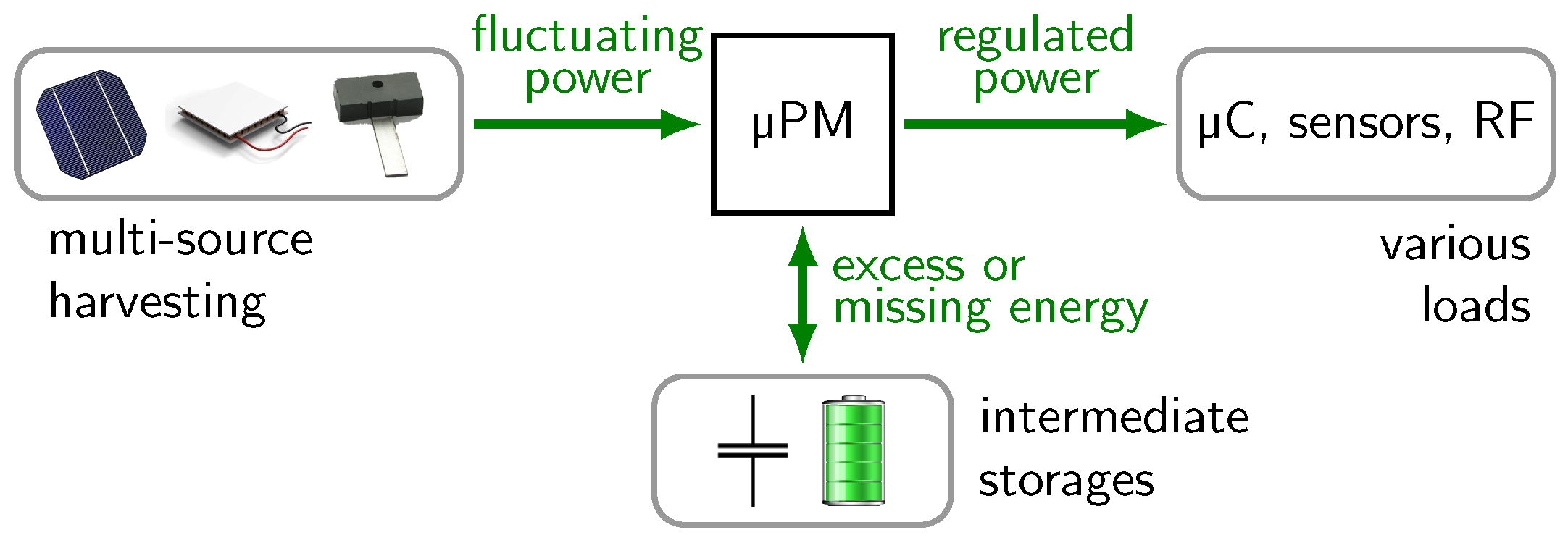
1.1. Energy Harvesting Powered Sensor Systems
1.2. Detailed Structure of a Power Management
1.3. Challenge: Realization of a µPM Using PMICs
1.4. Research Question
2. Related Work
2.1. Advanced Micro-Power Managements
2.2. Platforms for Testing and Prototyping
3. Methods and Materials
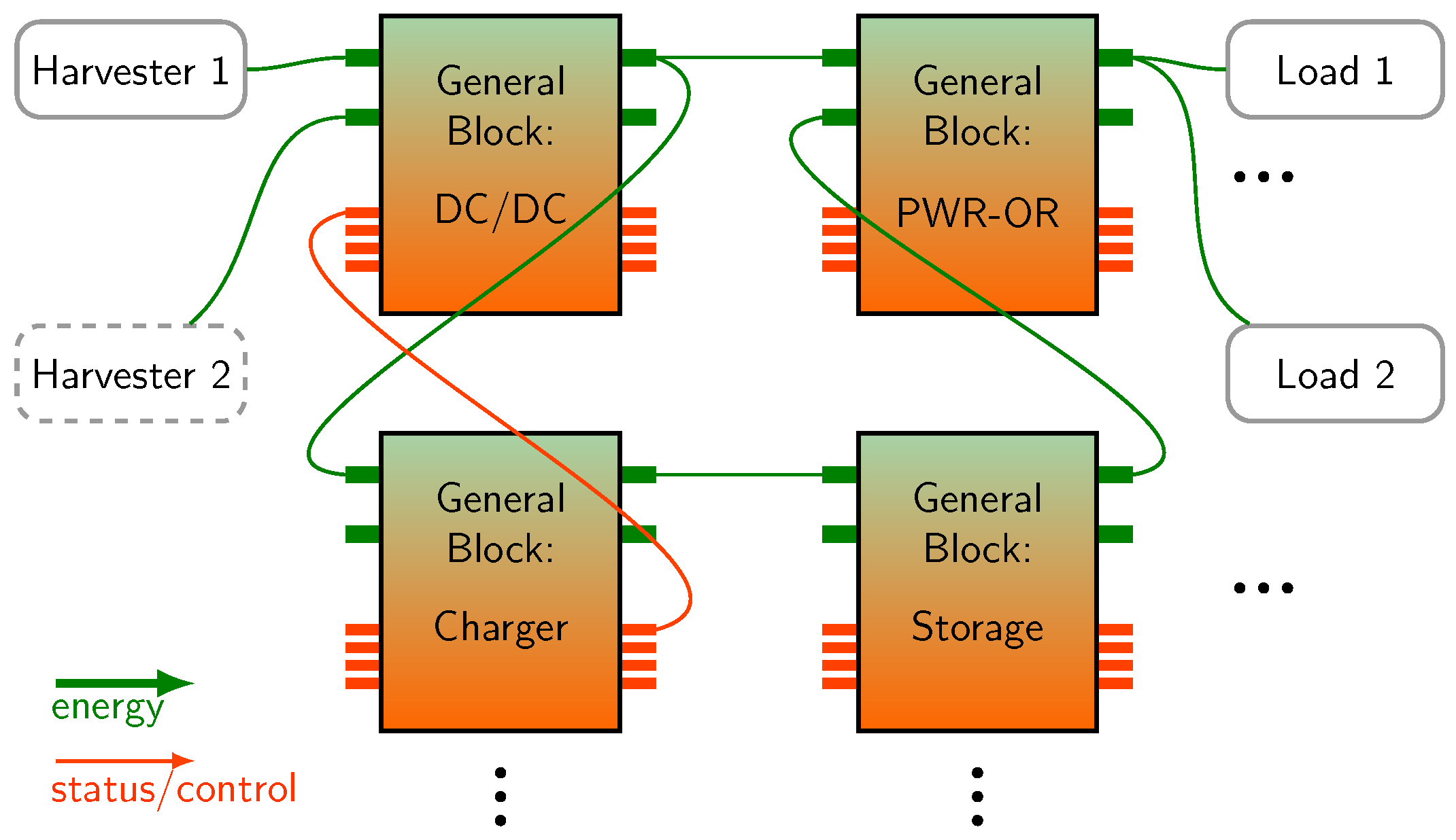
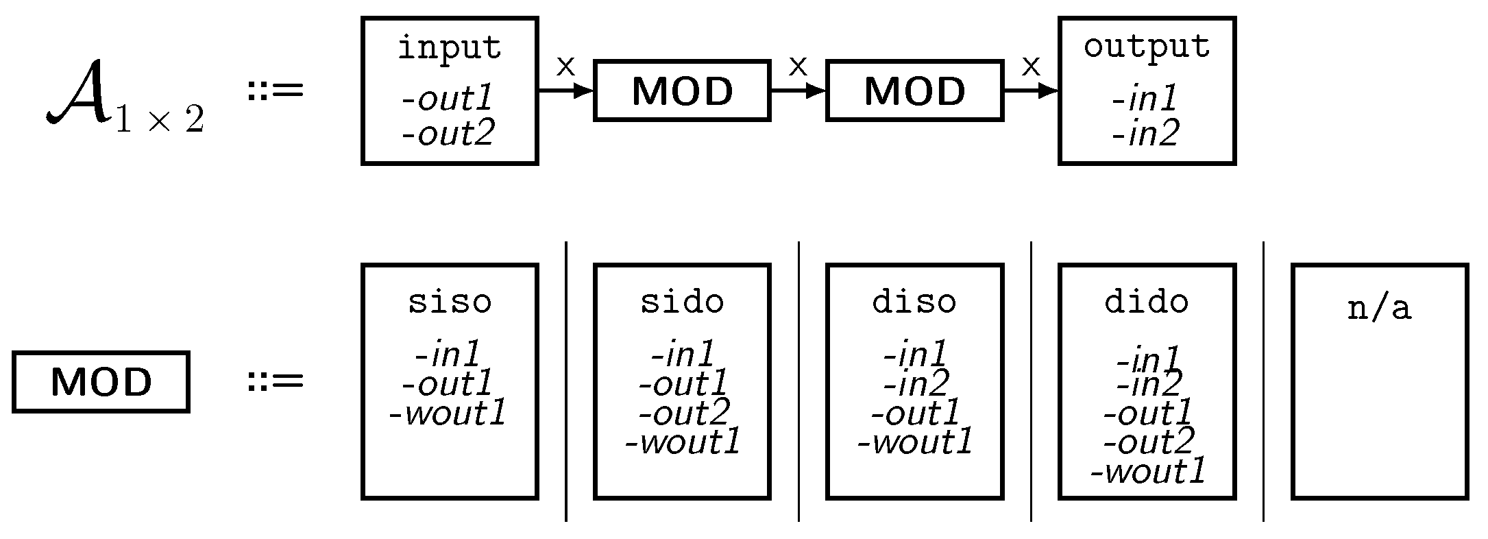
3.1. Our Concept—General Hardware Blocks
- (1)
- Every general block is capable of handling both energy and control signals. Nevertheless, the domains remain physically separated in the actual implementation (see Section 3.3).
- (2)
- Every general block has an interface of up to two power inputs and up to two power outputs. Furthermore, the interface includes up to four control inputs and up to four control outputs.
- (3)
- Energy storages are considered as general blocks like power converters. They are not external, as shown in Figure 1 but are part of the power management.
3.2. The implementation—From General Blocks to Modules
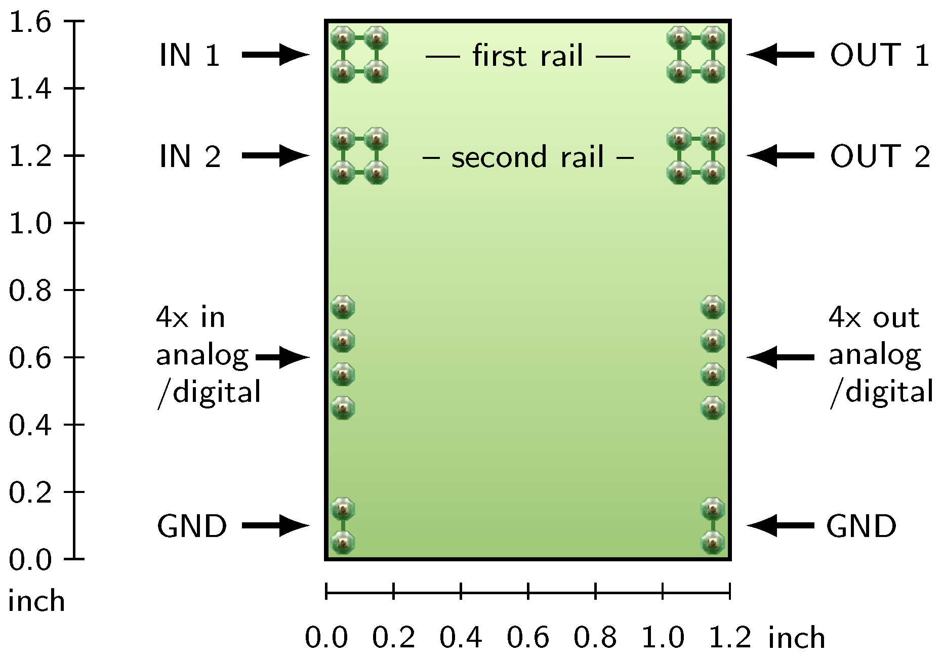
3.3. Standard Module Interface
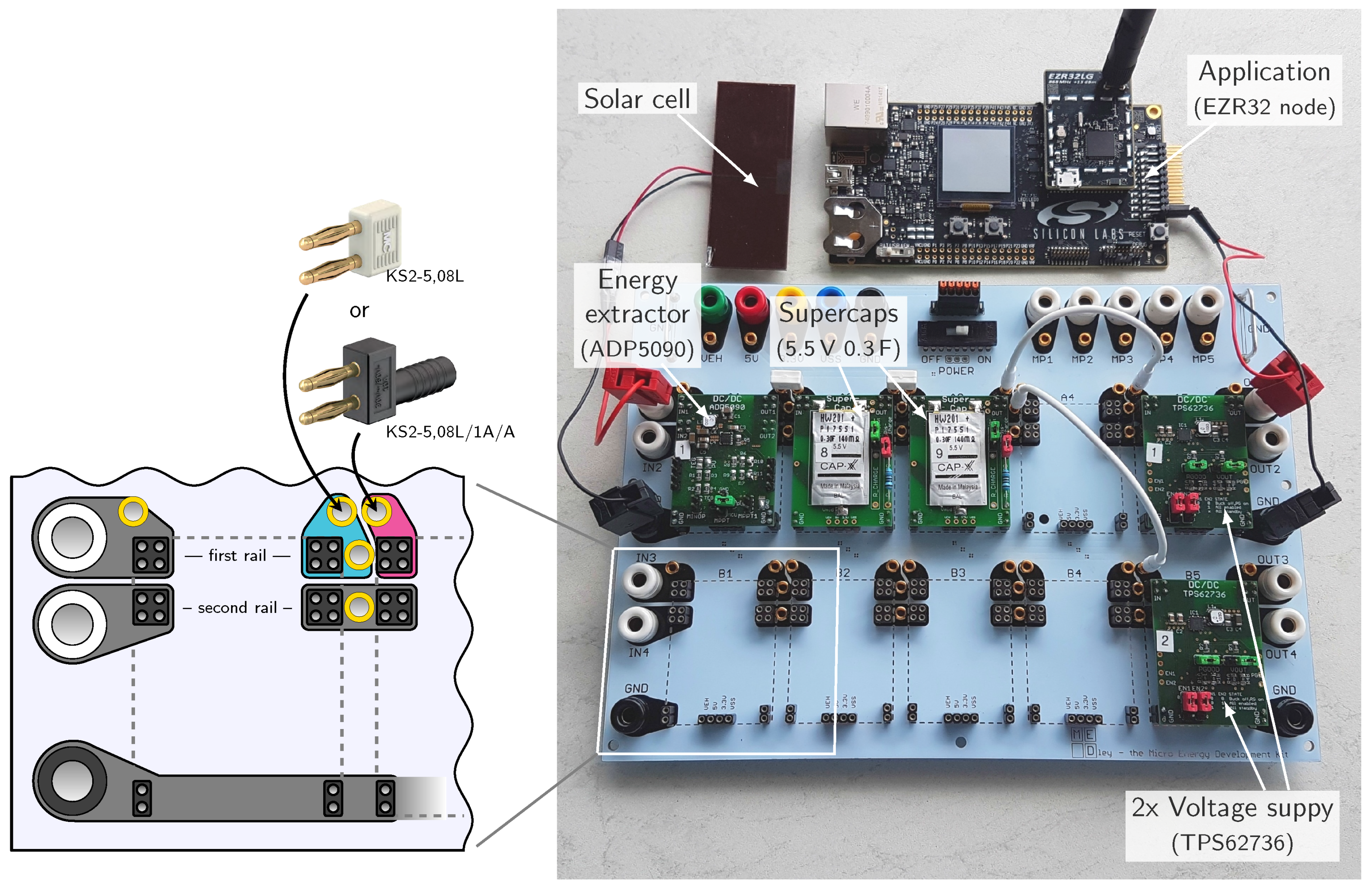
3.4. Base Board
3.5. Guidelines for the Modular Composition
- Organize your system concept or µPM circuit according to the structure shown in Figure 2. Identify the functions energy extraction, storage interaction and voltage supply.
- Choose suitable modules for the power functions and energy storages from the kit. Design missing modules according to the specification given in Section 3.3.
- Connect energy harvesters to the input banana plugs. This allows harvesters to be set up properly in the environment (e.g., the optimal orientation of a PV panel).
- Connect the supply pins of the load (e.g., a microcontroller or sensor board) to the output banana plugs or use the dummy load module for testing (see [33]).
- Place dc-dc converters for the primary energy extraction and voltage supply in the first row of the base board.
- Place additional functions like a second harvester, battery backup and switches for secondary loads in the second row.
4. Results
4.1. Parasitic Effects of Interconnections
4.2. Versatility Evaluation w.r.t. Base Board Sizes
4.3. Applicability Demonstration of the Modular Platform
5. Discussion
6. Conclusions
Acknowledgments
Author Contributions
Conflicts of Interest
Abbreviations
| ADC | analog-to-digital converter |
| CCCV | constant-current, constant-voltage (charging scheme) |
| CPLD | complex programmable logic device |
| EEPROM | electrically erasable programmable read-only memory |
| EH | energy harvesting |
| FPGA | field programmable gate array |
| FOCV | fractional open-circuit voltage (method) |
| I/O | input/output |
| LDO | low-dropout regulator |
| MLCC | multi-layer ceramic capacitor |
| MPP | maximum power point |
| PCB | printed circuit board |
| PMIC | power management integrated circuit |
| PV | photovoltaic (generator) |
| TEG | thermoelectric generator |
| µPM | micro-power management |
| WSN | wireless sensor nodes |
References
- Sikka, P.; Corke, P.; Overs, L.; Valencia, P.; Wark, T. Fleck—A platform for real-world outdoor sensor networks. In Proceedings of the 2007 3rd International Conference on Intelligent Sensors, Sensor Networks and Information, Melbourne, Australia, 3–6 December 2007; pp. 709–714. [Google Scholar]
- Kokert, J.; Torres Delgado, S.M.; Kasemann, M. Low-Cost Spektrometer zur Charakterisierung der Lichtverhältnisse für photovoltaisches Energy-Harvesting. In Proceedings of the Sensoren und Messsysteme 2014—Beiträge der 17. ITG/GMA-Fachtagung, Nürnberg, Germany, 3–4 June 2014. [Google Scholar]
- Kim, J.; Lynch, J.P. Experimental analysis of vehicle–bridge interaction using a wireless monitoring system and a two-stage system identification technique. Mech. Syst. Signal Process. 2012, 28, 3–19. [Google Scholar] [CrossRef]
- Zerger, A.; Rossel, R.V.; Swain, D.; Wark, T.; Handcock, R.N.; Doerr, V.; Bishop-Hurley, G.; Doerr, E.; Gibbons, P.; Lobsey, C. Environmental sensor networks for vegetation, animal and soil sciences. Int. J. Appl. Earth Obs. Geoinform. 2010, 12, 303–316. [Google Scholar] [CrossRef]
- Xiao, J.; Zou, X.; Xu, W. ePave: A self-powered wireless sensor for smart and autonomous pavement. Sensors 2017, 17, 2207. [Google Scholar] [CrossRef] [PubMed]
- Vullers, R.; Schaijk, R.; Visser, H.; Penders, J.; Hoof, C. Energy harvesting for autonomous wireless sensor networks. IEEE Solid State Circuits Mag. 2010, 2, 29–38. [Google Scholar] [CrossRef]
- Penella-López, M.T.; Gasulla-Forner, M. Powering Autonomous Sensors: An Integral Approach With Focus on Solar and RF Energy Harvesting; Springer Science & Business Media: Dordrecht, The Netherlands, 2011. [Google Scholar]
- Raghunathan, V.; Kansal, A.; Hsu, J.; Friedman, J.; Srivastava, M. Design considerations for solar energy harvesting wireless embedded systems. In Proceedings of the 4th International Symposium on Information Processing in Sensor Networks, Los Angeles, CA, USA, 25–27 April 2005; p. 64. [Google Scholar]
- Kim, S.; Vyas, R.; Bito, J.; Niotaki, K.; Collado, A.; Georgiadis, A.; Tentzeris, M.M. Ambient RF energy-harvesting technologies for self-sustainable standalone wireless sensor platforms. Proc. IEEE 2014, 102, 1649–1666. [Google Scholar] [CrossRef]
- Hudak, N.S.; Amatucci, G.G. Small-scale energy harvesting through thermoelectric, vibration, and radiofrequency power conversion. J. Appl. Phys. 2008, 103, 101301. [Google Scholar] [CrossRef]
- Mellit, A.; Rezzouk, H.; Messai, A.; Medjahed, B. FPGA-based real time implementation of MPPT-controller for photovoltaic systems. Renew. Energy 2011, 36, 1652–1661. [Google Scholar] [CrossRef]
- Shiau, J.K.; Wei, Y.C.; Lee, M.Y. Fuzzy controller for a voltage-regulated solar-powered MPPT system for hybrid power system applications. Energies 2015, 8, 3292–3312. [Google Scholar] [CrossRef]
- Jeong, J.; Jiang, X.; Culler, D. Design and analysis of micro-solar power systems for wireless sensor networks. In Proceedings of the 5th International Conference on Networked Sensing Systems, Kanazawa, Japan, 17–19 June 2008; pp. 181–188. [Google Scholar]
- Dondi, D.; Bertacchini, A.; Brunelli, D.; Larcher, L.; Benini, L. Modeling and optimization of a solar energy harvester system for self-powered wireless sensor networks. IEEE Trans. Ind. Electron. 2008, 55, 2759–2766. [Google Scholar] [CrossRef]
- Femia, N.; Petrone, G.; Spagnuolo, G.; Vitelli, M. Optimization of perturb and observe maximum power point tracking method. IEEE Trans. Power Electron. 2005, 20, 963–973. [Google Scholar] [CrossRef]
- Ou, T.C.; Hong, C.M. Dynamic operation and control of microgrid hybrid power systems. Energy 2014, 66, 314–323. [Google Scholar] [CrossRef]
- Oletic, D.; Razov, T.; Bilas, V. Extending lifetime of battery operated wireless sensor node with DC-DC switching converter. In Proceedings of the Instrumentation and Measurement Technology Conference (I2MTC), Hangzhou, China, 10–12 May 2011; pp. 1–5. [Google Scholar]
- Park, C.; Chou, P.H. AmbiMax: Autonomous energy harvesting platform for multi-supply wireless sensor nodes. In Proceedings of the 2006 3rd Annual IEEE Communications Society on Sensor and Adhoc Communications and Networks, SECON 2006, Reston, VA, USA, 28 Sepember 2007; Volume 1, pp. 168–177. [Google Scholar]
- Varley, J.; Martino, M.; Poshtkouhi, S.; Trescases, O. Battery and ultra-capacitor hybrid energy storage system and power management scheme for solar-powered Wireless Sensor Nodes. In Proceedings of the IECON 2012—38th Annual Conference on IEEE Industrial Electronics Society, Montreal, QC, Canada, 25–28 October 2012; pp. 4806–4811. [Google Scholar]
- Ongaro, F.; Saggini, S.; Mattavelli, P. Li-ion battery-supercapacitor hybrid storage system for a long lifetime, photovoltaic-based wireless sensor network. IEEE Trans. Power Electron. 2012, 27, 3944–3952. [Google Scholar] [CrossRef]
- Wang, W.; Cionca, V.; Wang, N.; Hayes, M.; O’Flynn, B.; O’Mathuna, C. Thermoelectric energy harvesting for building energy management wireless sensor networks. Int. J. Distrib. Sens. Netw. 2013, 9. [Google Scholar] [CrossRef]
- Li, H.; Zhang, G.; Ma, R.; You, Z. Design and experimental evaluation on an advanced multisource energy harvesting system for wireless sensor nodes. Sci. World J. 2014, 2014, 671280. [Google Scholar] [CrossRef] [PubMed]
- Magno, M.; Brunelli, D.; Sigrist, L.; Andri, R.; Cavigelli, L.; Gomez, A.; Benini, L. InfiniTime: Multi-sensor wearable bracelet with human body harvesting. Sustain. Comput. Inform. Syst. 2016, 11, 38–49. [Google Scholar] [CrossRef]
- Weddell, A.S.; Grabham, N.J.; Harris, N.R.; White, N.M. Modular plug-and-play power resources for energy-aware wireless sensor nodes. In Proceedings of the 2009 6th Annual IEEE Communications Society Conference on Sensor, Mesh and Ad Hoc Communications and Networks, Rome, Italy, 22–26 June 2009; pp. 1–9. [Google Scholar]
- Bader, S.; Oelmann, B. Short-term energy storage for wireless sensor networks using solar energy harvesting. In Proceedings of the 2013 10th IEEE International Conference on Networking, Sensing and Control (ICNSC), Evry, France, 10–12 April 2013; pp. 71–76. [Google Scholar]
- Nagel, J. Neues Konzept für die bedarfsgerechte Energieversorgung des Künstlichen Akkommodationssystems; Schriftenreihe des Instituts für Angewandte Informatik, Automatisierungstechnik am Karlsruher Institut für Technologie, KIT Scientific Publishing: Karlsruhe, Germany, 2012. [Google Scholar]
- Analog Devices. Available online: www.analog.com/en/products/power-management/battery-management/battery-charger-ic/adp5091 (accessed on 28 November 2017).
- Würth Elektronik. Available online: http://www.we-online.com/web/de/electronic_components/produkte_pb/demoboards/energy_harvesting/energy_harvesting.php (accessed on 28 November 2017).
- Würth Elektronik. Available online: http://www.we-online.com/web/en/electronic_components/produkte_pb/demoboards/gleanergy/gleanergy.php (accessed on 28 November 2017).
- Baker, T. Improved Energy Harvesting Efficiency in MCU Design; Technical Report; Future Electronics: Volketswil, Switzerland, 2012. [Google Scholar]
- Kokert, J.; Beckedahl, T.; Reindl, L.M. Development and Evaluation of a Modular Energy Management Construction Kit. In Proceedings of the Sensoren und Messsysteme 2016—Beiträge der 18. ITG/GMA-Fachtagung, Nürnberg, Germany, 10–11 May 2016; pp. 84–91. [Google Scholar]
- Kokert, J. Eagle design files of Medlay—A modular micro-power management layout kit. 2017. Available online: https://github.com/CubaLibre84/Medlay (accessed on 31 December 2017).
- Kokert, J.; Beckedahl, T.; Reindl, L.M. Evaluating Micro-Power Management of Solar Energy Harvesting using a Novel Modular Platform. J. Phys. Conf. Ser. 2016, 773, 012042. [Google Scholar] [CrossRef]
- Rensink, A.; Zambon, E. Available online: https://sourceforge.net/projects/groove/ (accessed on 28 November 2017).


| Ref. | Energy Generator(s) | Energy Extraction | Energy Supervisor | Storage Interaction | Energy Storage(s) | Voltage Supply |
|---|---|---|---|---|---|---|
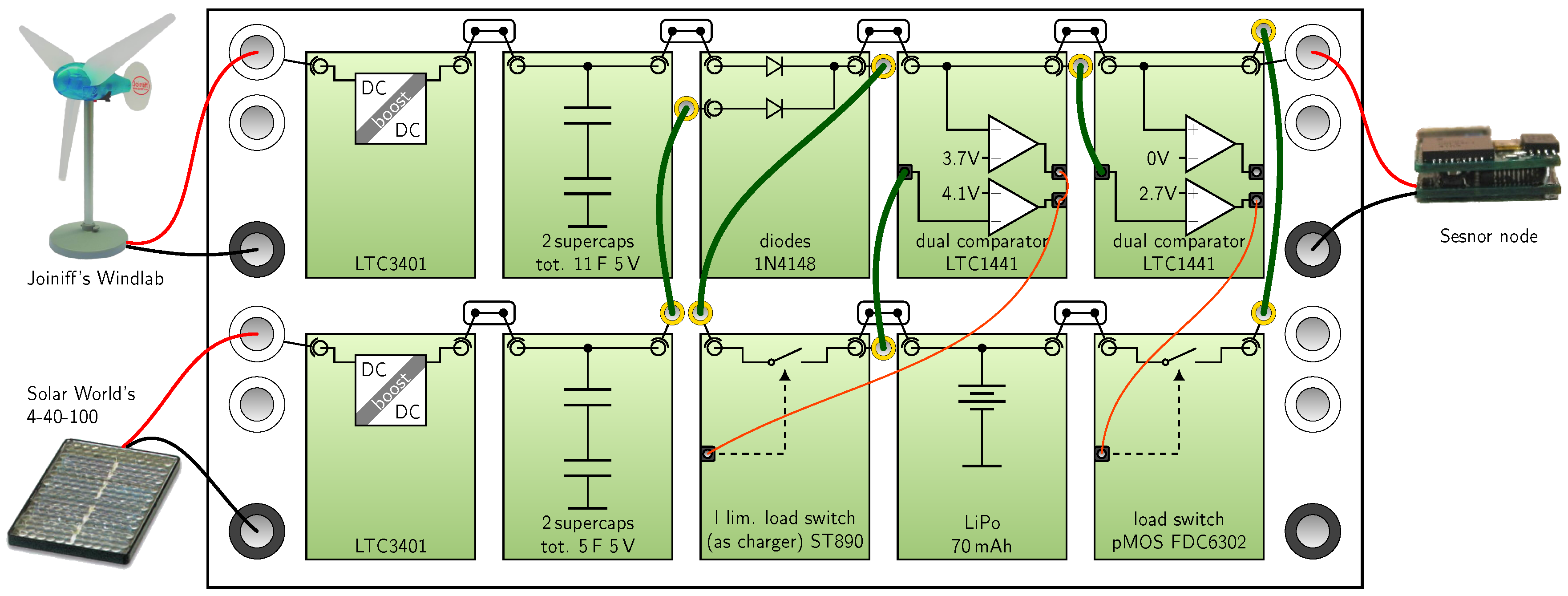
| [18] | solar 0.3 W + wind 0.5 W | LTC3401, pilot elem. and LTC1440 comp. | or-ing diodes, LTC1441 | curr. lim. switch ST890 | supercaps 11 F, 5 F and LiPo | pMOS selects energy source |
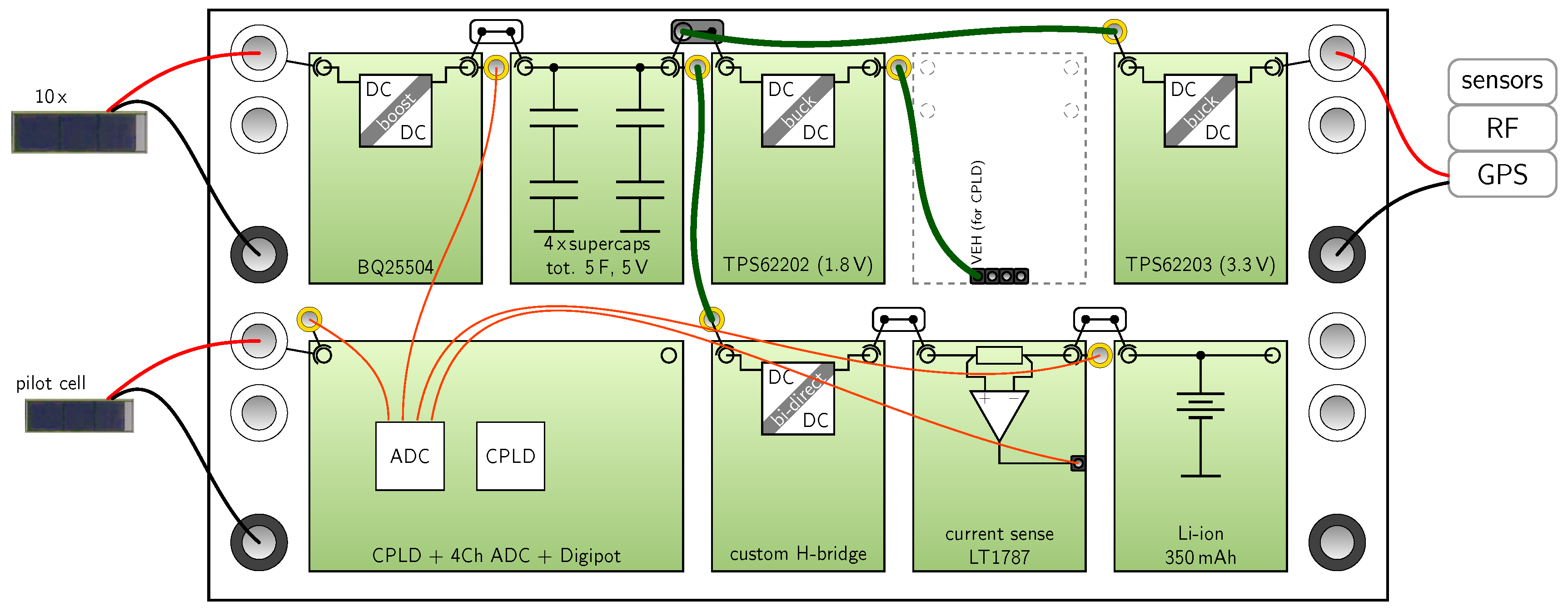
| [19] | 10 mini PV cells 17.9 mW | BQ25504, pilot cell, controlled by CPLD | CPLD and four ADCs | custom H-bridge buck/boost | supercap 5 F and 350 mAh Li-ion battery | buck conv. TPS6220x |
| [20] | solar 5 W | TPS43000 (sepic) | PIC µC and INA213 | TPS43000 (bi-dir. buck and boost) | supercap 3× 350 F 2.7 V and 680 mAh battery | connected to 3.3 V bus |
| [21] | TEG (250 mV at 4 K) | S-882Z18 (charge pump) + TPS61020 | µC for SoC detection | OV incl. in TPS61020 | 4x supercaps, 2.5 F, 5 V in total | TPS61220 |
| [22] | vibration + solar | LTC3401 and LTC3632 | passive: or-ing diodes | resistor divider, pMOS and diode | supercap 25 mF 5 V + 130 mAh Li battery | buck-boost (type not given) |
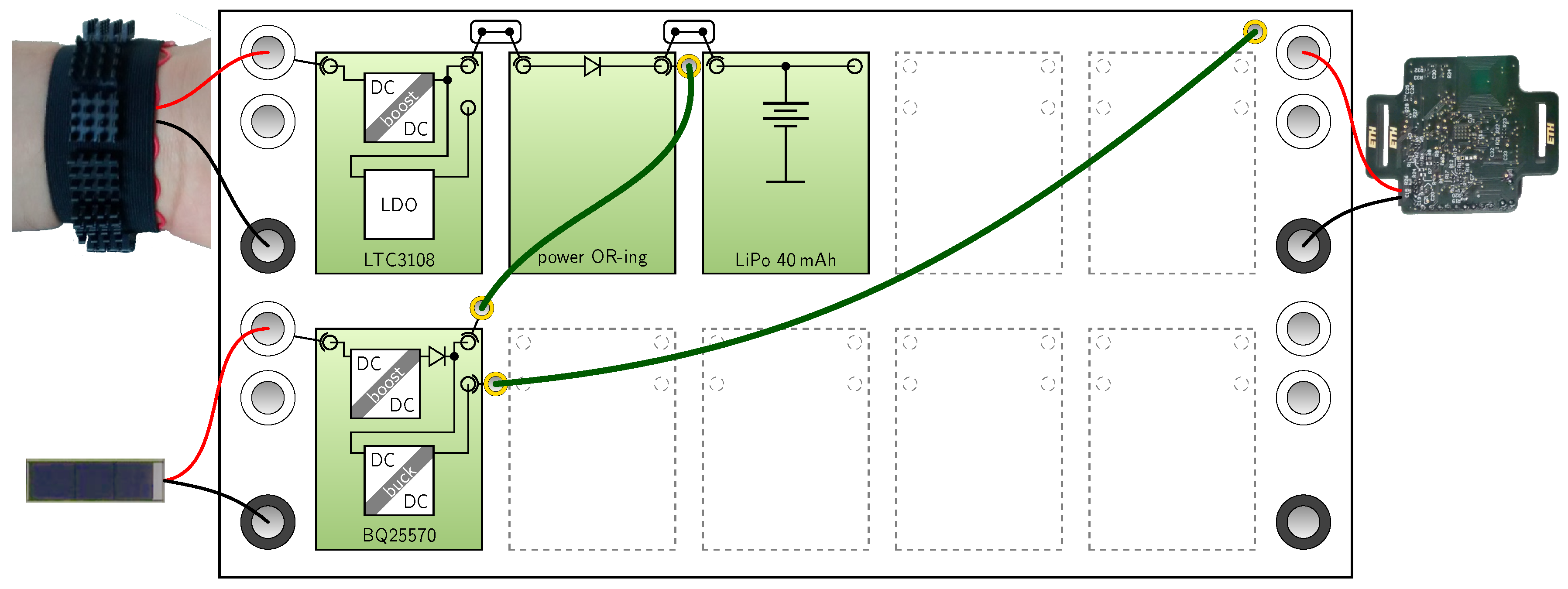
| [23] | TEG + solar | LTC3108 and BQ25570 | passive: or-ing diodes | UV and OV part of dc-dc conv. | LiPo 40 mAh 3.7 V | buck of BQ25570 |
| Type | IN 1 | IN 2 | OUT 1 | OUT 2 | A/D In | A/D Out |
|---|---|---|---|---|---|---|
| DC-DC (e.g., ADP5090, BQ25570) | harvester pos. input | battery backup input * | intermediate storage out | regulated output * | chip enable, force MPP * | power good * |
| AC-DC (e.g., LTC3109) | harvester pos. input | harvester neg. input | intermediate storage out | regulated output * | chip enable | power good * |
| Energy storage (e.g., supercap) | storage pos. pin | - | (short to IN1) | - | balancing tap * | 3-wire sense |
| Switch matrix (e.g., ADG888) | switches in | switches in* | switches out | switches out * | control | power good * |
| Quantity | Result |
|---|---|
| Contact resistance (module to board) | 5 ± 0.1 mΩ |
| 2 mm banana wire and 2 banana plugs | 7.8 0.1 mΩ |
| Isolation resistance (IN1 to GND) | >100 GΩ |
| Capacitance (IN1 to GND) | <1 pF |
| Capacitance (IN1 to IN2) | <1 pF |
| Scope (Method) | Cols. c | 1 | 2 | 3 | 4 | 5 |
|---|---|---|---|---|---|---|
| modules only | 1 row | 5 | 21 | 85 | 341 | 1365 |
| (Equations (1) and (2)) | 2 rows | 15 | 231 | 3655 | 58,311 | 932,295 |
| with wires | 1 row | 5 | 18 | 90 | 1094 | 82,879 |
| (Groove) | 2 rows | 24 | 2550 | 244,009 | >250,000 | |
| Name and Publication | Physical Modularity | Number of Harvesters | Energy Path Routing | Versatility of Power Converters | Versatility of Energy Storages |
|---|---|---|---|---|---|
| Weddell et al. [24] | max. 6 modules, ≅ mm | use 2 of 2 (pv, vibr.) | selected by analog MUX | converter fixed to harv. or storage | supercap and Li-battery |
| Bader et al. [25] | no, one PCB (size not given) | use 1 of 1 (pv) | fixed, interrupt by jumpers | fixed (LTC3105 and MAX17710) | supercap and thin-film bat. |
| Nagel et al. [26] | 2 to 5 modules, mm | use 1 of 1(rf) | free assignment to 32-pin bus | designed for one per card | designed for one per card |
| ADP5091 Demo [27] | no, one PCB mm | use 1 of 2 (pv, teg) | fixed, interrupt by jumpers | ADP5091 (fixed) | fixed, one LiPo (240 mAh) |
| WE EH to go [28] | no, one PCB mm | use 1 of 3 (pv, teg, ext.) | fixed, interrupt by jumpers | select between 4 dc-dc by jumpers | MLCC array (15 × 100 F) |
| WE Gleanergy [29] | no, one PCB mm | use 1 of 3 (pv, teg, ext.) | fixed, interrupt by jumpers | select between 4 dc-dc by jumpers | MLCC array and supercaps |
| Future Electronics EH [30] | max. 4 slave modules ≅ mm | use 1 of 1 (pv) | fixed, interrupted by 4 relays | select between 2 dc-dc modules | 1 supercap module (2 F, V) |
| this work | max. 10 modules, mm | use 2 of 2 (arbitrary) | base board and 2 mm banana plugs | fully replaceable, >10 types available | fully replaceable, >5 types avbl. |
© 2018 by the authors. Licensee MDPI, Basel, Switzerland. This article is an open access article distributed under the terms and conditions of the Creative Commons Attribution (CC BY) license (http://creativecommons.org/licenses/by/4.0/).
Share and Cite
Kokert, J.; Beckedahl, T.; Reindl, L.M. Medlay: A Reconfigurable Micro-Power Management to Investigate Self-Powered Systems. Sensors 2018, 18, 259. https://doi.org/10.3390/s18010259
Kokert J, Beckedahl T, Reindl LM. Medlay: A Reconfigurable Micro-Power Management to Investigate Self-Powered Systems. Sensors. 2018; 18(1):259. https://doi.org/10.3390/s18010259
Chicago/Turabian StyleKokert, Jan, Tobias Beckedahl, and Leonhard M. Reindl. 2018. "Medlay: A Reconfigurable Micro-Power Management to Investigate Self-Powered Systems" Sensors 18, no. 1: 259. https://doi.org/10.3390/s18010259
APA StyleKokert, J., Beckedahl, T., & Reindl, L. M. (2018). Medlay: A Reconfigurable Micro-Power Management to Investigate Self-Powered Systems. Sensors, 18(1), 259. https://doi.org/10.3390/s18010259