1. Introduction
With the advancements in material sciences, the sensor research field is heading towards the implementation of an ultimate “nerves system” that can be utilized to sense various, if not all, physical, chemical and biological aspects not only of living beings but also of natural and/or man-made surroundings. This is evident from current trends towards the “smart city” concept, where the implementation of sensor systems to monitor the physical conditions of the civil structures of a city plays a vital role in addressing the economic benefits and ethical need for safe and sustainable infrastructures.
One main stakeholder of the said smart concept is the employment of appropriate structural health monitoring (SHM) schemes that can “sense” the physical conditions of structures to ensure their safe and efficient operation. Conventional techniques used for SHM are limited to electrical means, i.e., the use of strain gauges for strain measurement, for instance [
1], where a pool of wires carrying a current not only poses a safety threat, but also is tedious to install and is not resource-efficient. Following the introduction and use of fiber optics during the telecommunications boom in the 1990s, both research and industry confidence had gathered momentum in the use of fiber optic technology not only for telecommunications purposes but also for sensing applications. Recent research by some of the authors [
2] has also looked into the possibility of embedding sensors in smartphones, paving way for the wider application and use of fiber optic technology. In terms of SHM applications, fiber optic sensors (FOSs) have considerable advantages over their conventional electrical counterpart, i.e., being small in size, light weight, electrically passive and hence immune to electromagnetic interference. Since optical fibers are made of silica (glass), they are robust and can withstand harsh environments, i.e., FOSs can be used in high-temperature [
3], radiation-hard [
3,
4,
5] and corrosive environments [
6] where electrical sensors cannot be used [
7]. Due to the low light attenuation of optical glass fibers, they can be multiplexed and interrogated over several kilometers. The multiplexing and wider bandwidth capabilities render FOSs most suitable, therefore, when extracting data from a vast amount of sensing elements such as those required for SHM of larger areas, i.e., SHM of sewerage tunnels [
7,
8,
9], dams [
10] and bridges [
11,
12].
Conventional approaches to SHM using FOSs have been generally focused on grating-based sensors that are mounted to the structure afterwards, i.e., using epoxy for instance, so that effective measurement of physical parameters, such as strain [
12,
13], can be obtained. While these techniques are a step forward from electrical strain gauges, the need for specialist personnel to install them on the structure and the relative tediousness of having to glue them on the surface makes these schemes less attractive and flexible for civil engineers [
14]. If the sensory elements can somehow be embedded with the strengthening mechanism of a structure, it would not only address the issue of having to install the sensors separately, but it would also pave way to a relatively more accurate system that would not require an intermediate transfer agent, e.g., the epoxy. Thus, it is of great interest to design a sensor system that could be “embedded” into the strengthening mechanism of a structure, providing the dual purposes of sensing and strengthening, saving a considerable amount of time and money.
Advances in material fabrication and processing engineering have rendered a step towards the possibility of “smart textiles” incorporating embedded sensors inherently in structures/textiles in order to not only mitigate the risk of failure due to an overload or unwanted inhomogeneity resulting from the fabrication process [
15], but also for the identification, assessment and location detection of physical parameters, i.e., such as strain, experienced by the composite containing the sensors [
16,
17]. The integration or embedding of the sensors, in general, is achieved by sewing or warp-knitting the sensors into the host structure [
18]. The interrogation of the sensors is then achieved by the utilization of fiber Bragg grating (FBG) [
13,
15,
19] and different distributed fiber optic sensor systems [
18].
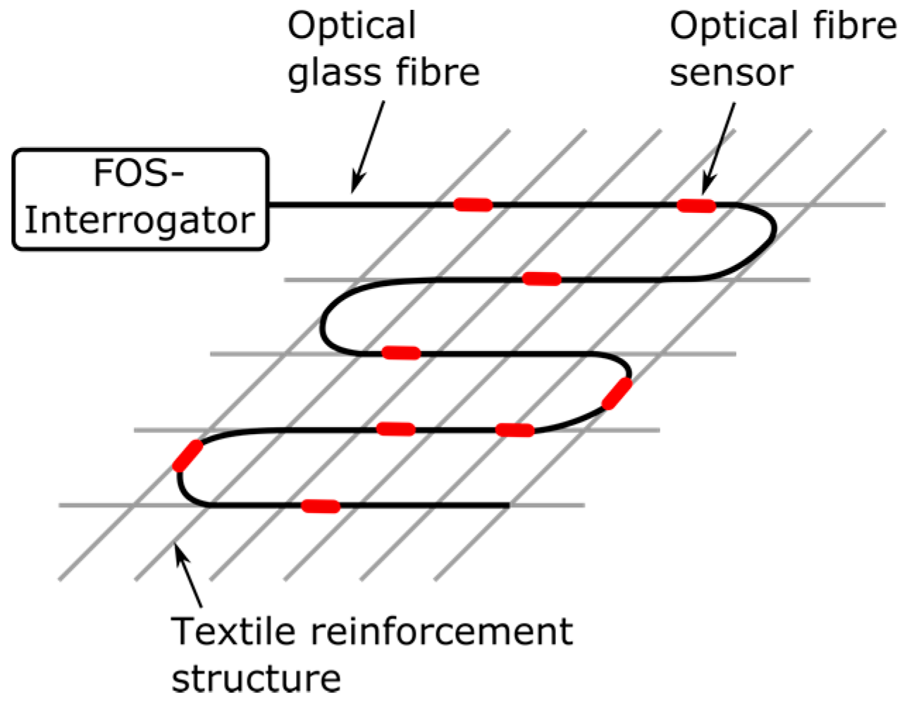
In light of the discussion above, the work presented here introduces the design and evaluation of a tailored functionalized carbon structure (FCS), used for strengthening, with integrated optical fiber sensors to extract important SHM parameters (e.g., strain), and a fiber optic crack sensor based on a textile net structure (TNS) to be used for SHM. The work proposed here explicitly targets crack and strain detection in concrete-based composite structures, specifically in line with and as a progression of former work on SHM of sewerage tunnels [
8,
9] of some of the authors. The “embroidery” principle of operation of both proposed fiber optic sensor concepts is shown in
Figure 1. Thus, the new design of optical fiber sensors acts simultaneously as the reinforcement as well as the SHM system, not only making it more practical and hence easier for civil engineers to employ, but also saving time and money while ensuring more accuracy compared to conventional FOSs (which rely on a transfer agent).
3. Carbon Reinforcement Structures with Integrated Optical Fiber Strain Sensors
Developments in material sciences and nano-technology, especially in polymer engineering, have rendered a variety of sensing possibilities, one recent advancement being the utilization of carbon fibers and carbon nanotubes not only for various sensing purposes [
20] but also as strengthening agents, i.e., the utilization of carbon fiber reinforcement polymer (CFRP) for strengthening structures such as railway bridges [
12]. In addition, the relatively small size and large flexibility of optical fibers opens the possibility of embedding optical fibers in carbon reinforcement structures directly during the manufacturing process [
21]. This will not only enable carbon reinforcement structures to additionally monitor measurements such as strain and cracks, but will also enhance the protection of the fragile sensing elements, i.e., especially in the case of using fiber Bragg gratings [
12]. In addition, optical fibers embedded in a grid-like composite would be able to perform multi-point sensing, paving the way to create a profile of the target measurement, i.e., a strain profile of a bridge, for instance.
This approach also provides a promising potential for utilizing FCSs to be tailor-made for concrete composite applications, both as a strengthening and sensing agent, and thus addressing two important aspects simultaneously. The FCS manufacturing process could therefore be “designed” in a manner, to target a specific shape for instance, that could be utilized to create the “embedded” sensing/strengthening mechanism mentioned above, as is also evident from the work presented here.
3.1. Functionalized Reinforcement Sensor Design, Material and Fabrication
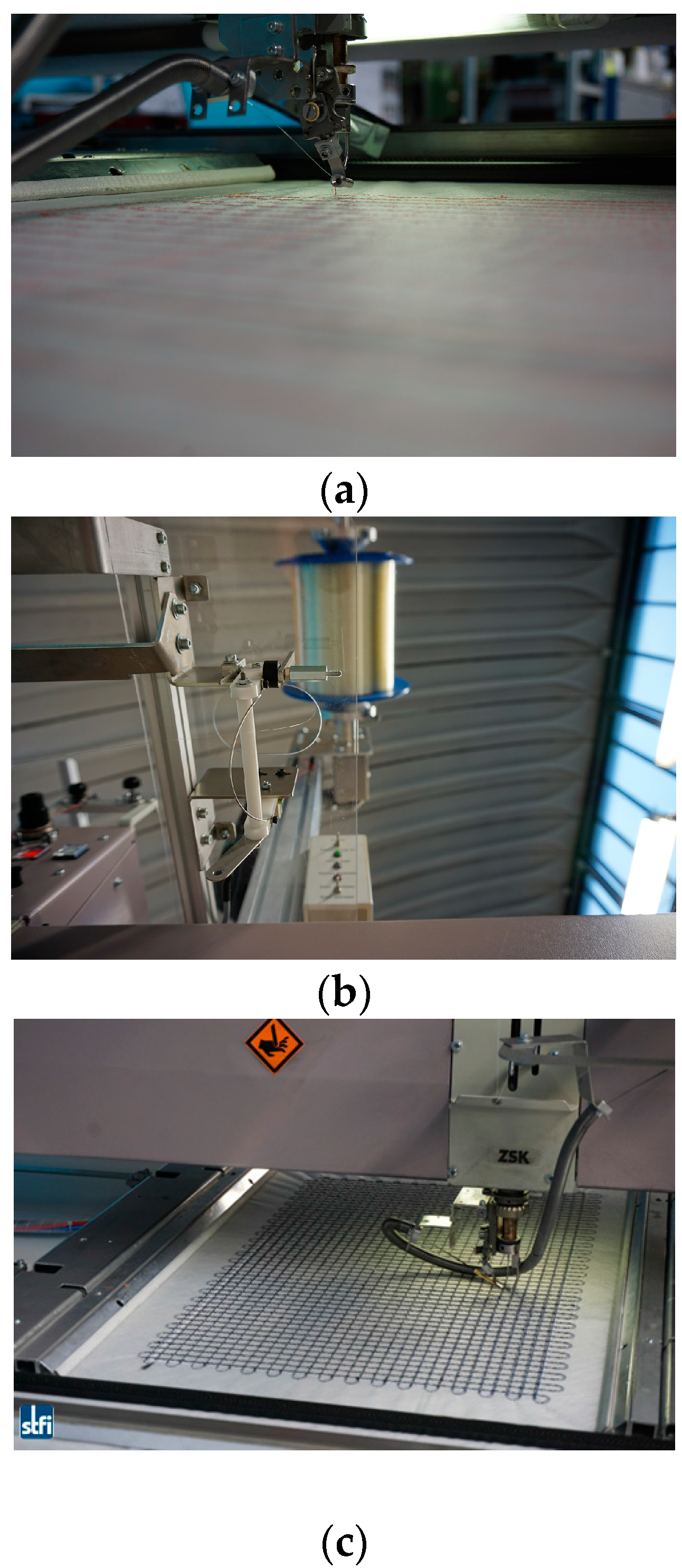
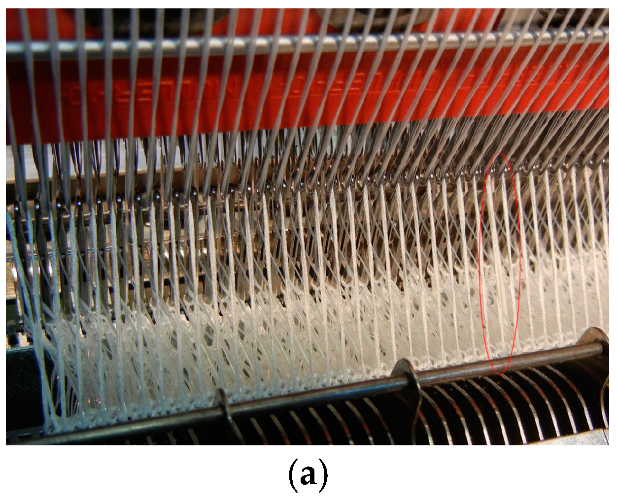
The embroidery technique that is employed for the FCS fabrication was also developed at STFI. This was achieved through the manufacturing of the functionalized carbon structure (FCS) with the optical fiber simultaneously “woven” to the FCS. To do so, carbon fibers and optical fiber sensors were processed to produce grid-like elements. The advantage of this technique is the possibility of fabricating a tailored carbon structure, i.e., several layers of carbon filaments with up to 50 k filament fibers (corresponding to 3200 tex), as well as different shapes of grid structures, depending on the targeted application and purpose.
Figure 4a,b depict the modified embroidery machine that was used for simultaneous processing of the carbon fiber filaments and optical fibers used for the work presented here.
The fabrication of the “interwoven” carbon/optical-fiber strands was followed by the realization of a tailored textile-based FCS. To do so, first the optical fiber (Corning
® ClearCurve
® single-mode fiber with acrylate coating) and carbon filaments were embroidered on a polyvinyl alcohol (PVA) nonwoven substrate. Several layers of carbon fibers were incorporated subsequently on the PVA nonwoven substrate in order to obtain the required tailored grid-like structure. Upon completion of the fabrication process, the nonwoven substrate was then removed by dissolving the PVA in hot water (approximately 50 °C). The fabricated functionalized grid reinforcement structure embroidered on the PVA substrate is shown in
Figure 4c.
3.2. Experimental Set-Up to Evaluate FCS
The careful characterization of the sensor’s performance is of high importance, given the fact that the integrated optical fiber is intended to be utilized for the SHM of carbon-reinforced elements. The characterization, in particular, should include the evaluation of force transfer from the carbon structure to the optical fiber as will be experienced in the target application, and any hysteresis and/or drift of the sensor.
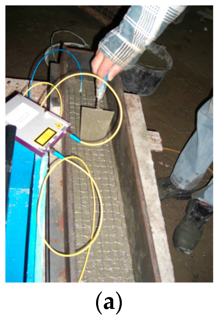
When applied in the laboratory environment, interferometric techniques have the advantage of providing a relatively cost-efficient (no special fibers and interrogation systems are required) and accurate approach to characterize the performance of optical fiber sensors. Therefore, for an initial proof-of-principle experiment on the performance of the FCS, a Mach-Zehnder interferometric (MZI) set-up was applied. The set-up was designed so that the changes that are introduced due to the applied force on the optical fiber (which was incorporated in the FCS) can be detected, and hence the resulting force transfer between the carbon reinforcement structure and the optical fiber can be evaluated.
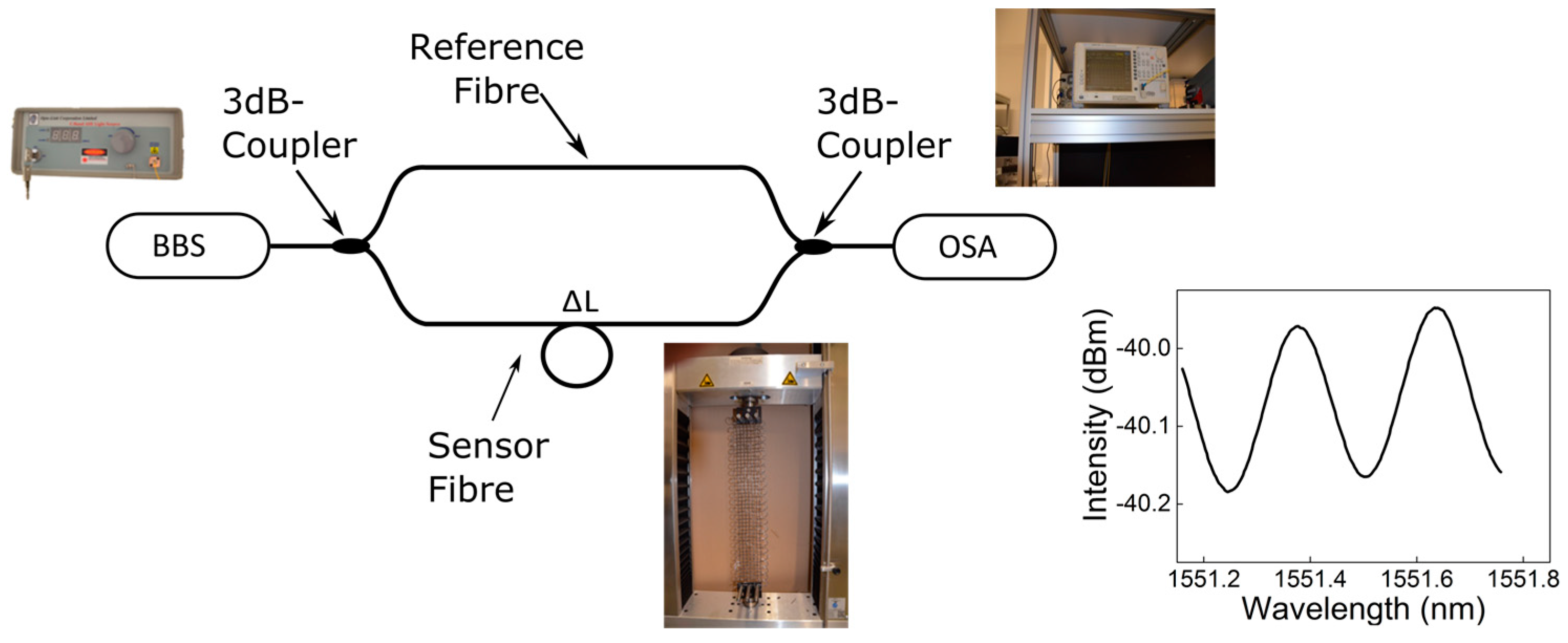
The fiber-optic MZ interferometer that was used for this purpose is shown in
Figure 5. The set-up consists of a broadband light source (BBS, Opto-Link C-Band ASE, Hong Kong, China), an optical spectrum analyzer (OSA, ANDO AQ6317B, Tokyo, Japan), two 3 dB couplers and single-mode fiber optic reference/sensor arms. Any force-related change of the sensor arm causes a phase difference (Δφ) between the light (of wavelength
λ) traveling in both fiber arms, resulting in an interference pattern change, as displayed in the subset of
Figure 5. The obtained phase difference can be used to calculate the length change of the MZI.
3.3. Evaluation of Sensor Performance of the FCS
To fully evaluate the fiber optic strain sensor’s performance, two aspects are highlighted: first, the evaluation of the force transfer between the carbon filaments and the optical fiber; second, the evaluation of the “sensors embedded structure” to assess whether this structure can be applied for sensing purposes as well. To assess the two aspects, the evaluation of the fiber optic strain sensor’s performance was thus divided into two sections. In order to only characterize the force transfer between the carbon filament and the optical fiber, only one-dimensional (1D) functionalized carbon structures were initially investigated. However, for structures that have to provide both strengthening and sensing mechanisms, two-dimensional (2D) FCSs are required. Therefore, subsequently, a two-dimensional FCS was characterized and its sensitivity to longitudinal and normal forces was evaluated.
In
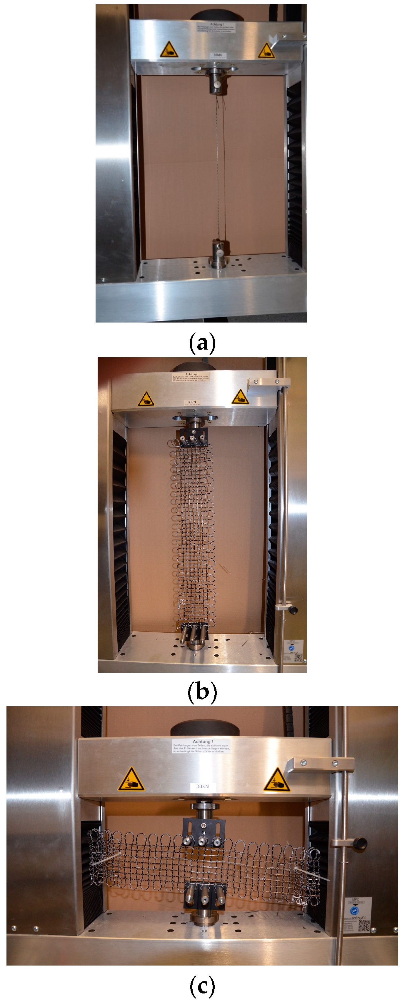
Figure 6, the experimental set-up to evaluate the sensor’s performance for the functionalized carbon structures based on a tensile testing machine, MFC T3000, is illustrated. In
Figure 6a, the force transfer between the carbon filament and the optical fiber is investigated. Following this, the force transfer of longitudinal and normal forces of the 2D-FCS is explored, as shown in
Figure 6b,c.
For the force transfer evaluation between the carbon filament and the optical fiber, a one-dimensional carbon skein 30 cm in length and a 1600 tex carbon filament that was integrated with a Corning® ClearCurve® single-mode fiber with acrylate coating was used. The functionalized carbon skein was embroidered first on the PVA nonwoven substrate and then cut into 30-cm-long samples following the removal of the PVA (water-dissolved). This was then followed by the splicing of the integrated optical fiber to the above MZ interferometer and the sensor’s performance was characterized using the tensile testing machine MFC T3000. The force transfer between the textile carbon structure and optical fiber was evaluated by mounting only the carbon structure to the tensile testing machine and subjecting the structure to applied force in the range from 0 to 350 N. Furthermore, before the measurement started, the 1D FCS was pre-strained at a force of 5 N.
Following the evaluation of the 1D structures, the sensor’s performance for the 2D functionalized carbon structures was evaluated. The 2D structures were fabricated using the same fabrication technique described above. The 2D structures with 1600 tex were 520 × 110 mm
2, and a grid spacing of 10 mm, and the optical fiber positioned vertically in the middle of the grid were utilized. Upon integration, the integrated optical fiber was spliced to the MZ interferometer and the sensor’s performance was characterized (
Figure 6b,c). In order to avoid breaking the carbon filament and the optical fiber during the experiments, the maximum length change in the horizontal and vertical directions was ≤1%.
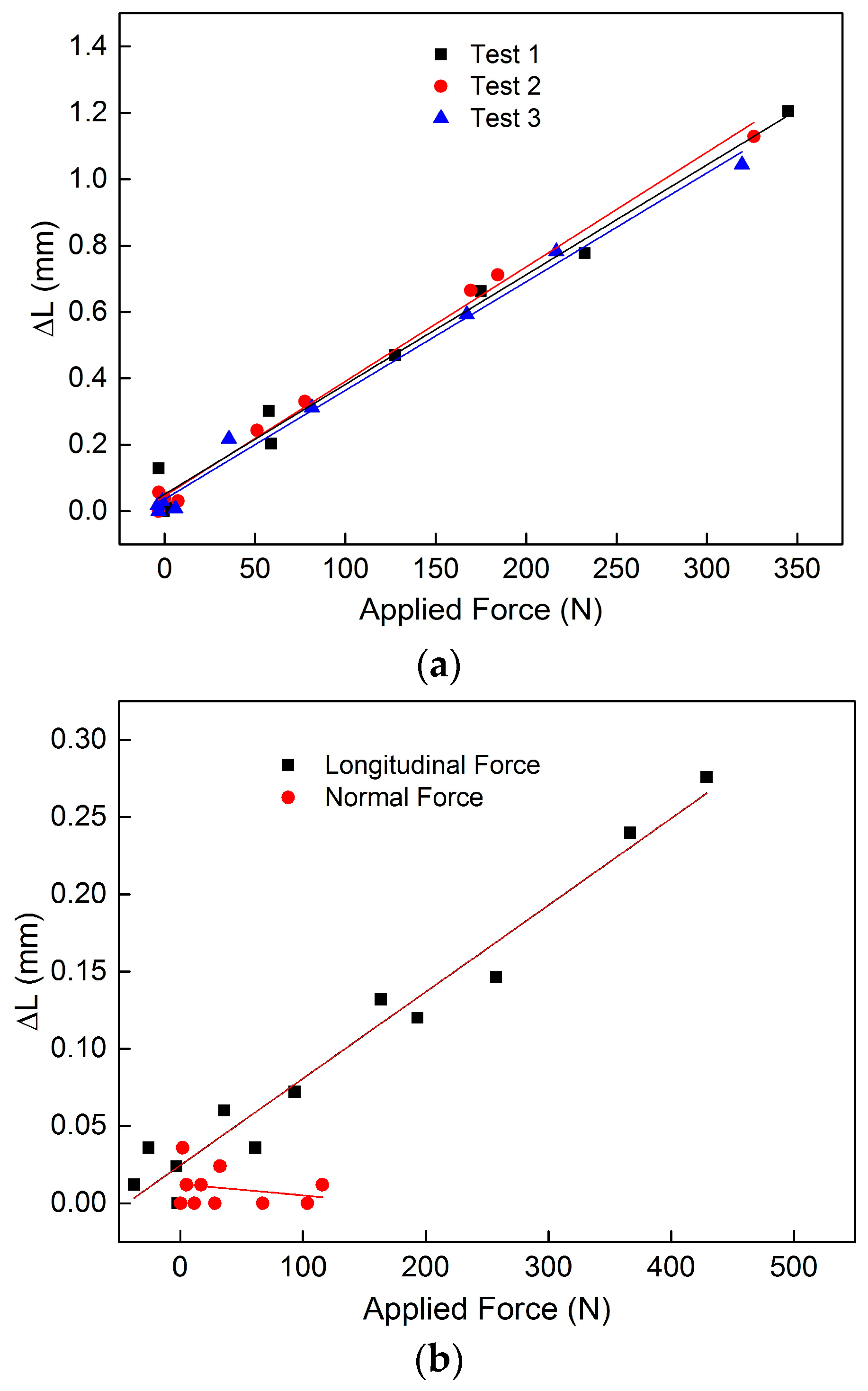
The force transfer of the 1D FCS thus evaluated is shown in
Figure 7a. Three subsequent tests were performed for the 1D FCS in order to characterize the hysteresis and drift. As is obvious from
Figure 7a, a good correlation between the applied force and the measured length change Δ
L can be seen, with a linearity of 0.0033 mm/N (±1.4%) for forces up to 350 N. Furthermore, a relatively small standard derivation of 0.042 mm/N was obtained for the one-dimensional FCS. The measured sensor performance of the 2D-FCS when longitudinal and normal forces were applied is shown in
Figure 7a,b. Before the measurement, the 2D FCS was pre-strained at a force of 100 N. The 2D FCS shows a good correlation with the applied longitudinal forces (5.6 × 10
−4 mm/N) and no cross-sensitivity to normal forces, as can be seen from
Figure 7b. The reduced sensitivity to the applied force compared to the 1D case can be attributed to the increased cross-section of the 2D FCS. Hence, depending on the tex number and the geometric shape of the FCS, the sensitivity and measurement range can be optimized. Furthermore, a relatively small hysteresis and drift to the applied force were observed (not shown), which is consistent with the results achieved for the 1D FCS. The characterized FCSs that are shown in
Figure 7a,b are based on acrylate-coated optical glass fibers. Currently, the influence of different fiber coatings on the sensor performance of the FCS is being investigated.
4. Discussion
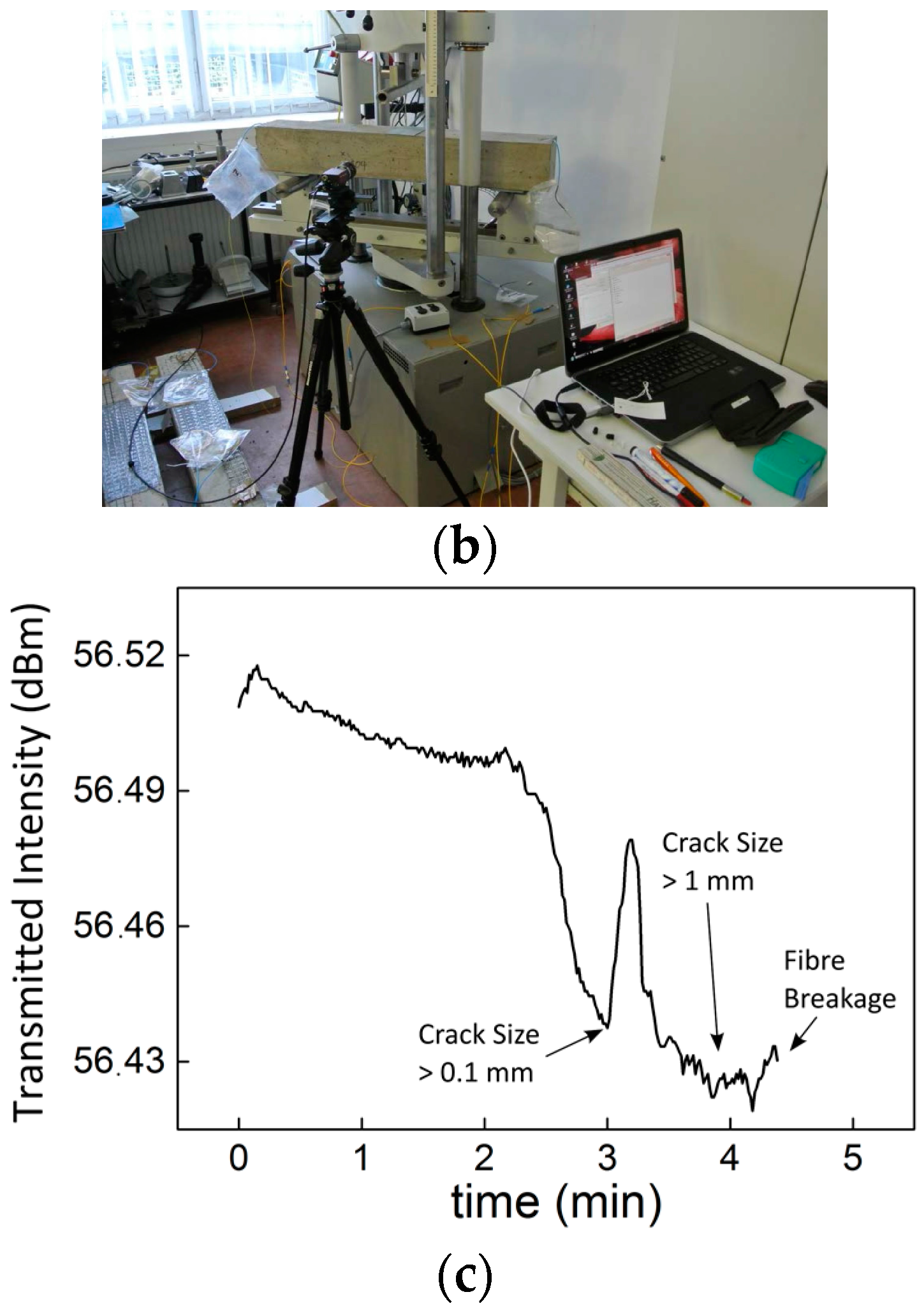
The two different functionalized reinforcement structures with integrated optical fiber sensors for SHM applications were successfully realized using textile stitching techniques. The techniques ensured careful integration of the optical fibers, which is essential for realizing reliable distributed sensor systems. The fiber optic crack sensor provides a simple means to detect crack-related failures of concrete structures and responses to cracks ≥1.4 mm. Since the transmitted light intensity of the fiber optic crack sensor shows no correlation to the crack size, as illustrated in
Figure 3c, only the breakage of the fiber can be used as an indication of the status of the structural health. Therefore, once the sensor is activated, i.e., the textile structure transfers the crack and breaks the optical fiber, the TNS-based crack sensor has to be renewed. Consequently, the fiber optic crack sensor system is only suitable for qualitative monitoring applications, i.e., the sensor can only provide information about whether a structure is still operating or has failed, and for situations where, in case of a failure, the whole concrete element has to be renewed, which is, e.g., relevant for concrete sewerage pipes [
8,
9]. For sewerage tunnels, the most common inspection technique is currently based on a remote video camera–based system. Because of the complex nature of this inspection process, it is usually only applied at regular intervals. Therefore, the fiber optic crack sensor provides a simple and cost-efficient approach for the continuous monitoring of the structural health of concrete-based sewerage tunnels.
In contrast, the carbon reinforcement structures with integrated optical fiber strain sensors can be applied for quantitative SHM applications, and thus can be used to determine the status of a structure and hence are able to predict the event of a failure. Combined with a MZI interrogation technique, the developed FCSs show a linear response to applied longitudinal forces with a relatively small hysteresis and drift (0.0033 mm/N (±1.4%)), with a standard derivation of 0.042 mm/N for 1D FCS. Furthermore, since the cross-sensitivity to normal forces can be neglected, the direction of the applied force can be determined depending on the position of the FCSs relative to the measured object. Therefore, when the MZI interrogation technique is replaced for in-field use by FBGs or stimulated Brillouin scattering, the developed FCSs provide a novel means for distributed SHM. Currently, the operation of the FCS in combination with FBG sensors is being explored when two-dimensional structures are embedded in concrete elements.
5. Conclusions
The work presented here highlights the design, realization, and evaluation of fiber optic sensors embedded in carbon and textile reinforcement structures for the application of concrete composite structures, respectively. The fiber optic crack sensor is based on light attenuation measurement, where the optical fiber was stitched on the surface of a textile net structure which was then placed in a concrete block that was subjected to crack formation. The sensor responded well to cracks resulting from three-point flexural tests (until destruction) and, due to the breakage of the optical fiber, the crack locations could be identified using the OTDR technique. On the other hand, the functionalized carbon structures were based on an optical fiber interwoven with carbon fiber filaments (simultaneously during manufacturing) which were then exposed to applied force and interrogated using a MZI set-up. The functionalized carbon reinforcement samples indicated a strong and reliable correlation between the applied force and measured elongation with relative small hysteresis and drift. Both reported fiber optic sensor approaches are based on single-mode optical fiber with acrylate coating. However, depending on the application, multi-mode (MM) fiber can also be applied. The strength of the sensor approaches proposed lies in the fact that sensing and strengthening can be simultaneously achieved, saving considerable cost and time that would otherwise be required. Furthermore, the use of appropriate and effective technology, i.e., OTDR, FBGs or stimulated Brillouin scattering, also plays a key role in achieving timely, reliable and reproducible status information for a broad range of structures. The evaluation of both sensor schemes has provided promising results in the approach applied for opening up new research avenues in multi-purpose sensing mechanisms for SHM applications.


 ,
, 