
Nano-Anatase TiO2 for High Performance Optical Humidity Sensing on Chip

Abstract
:1. Introduction
2. Experimental
2.1. Preparation of the Materials
2.2. Synthesis of Nano-Anatase TiO2 Powder
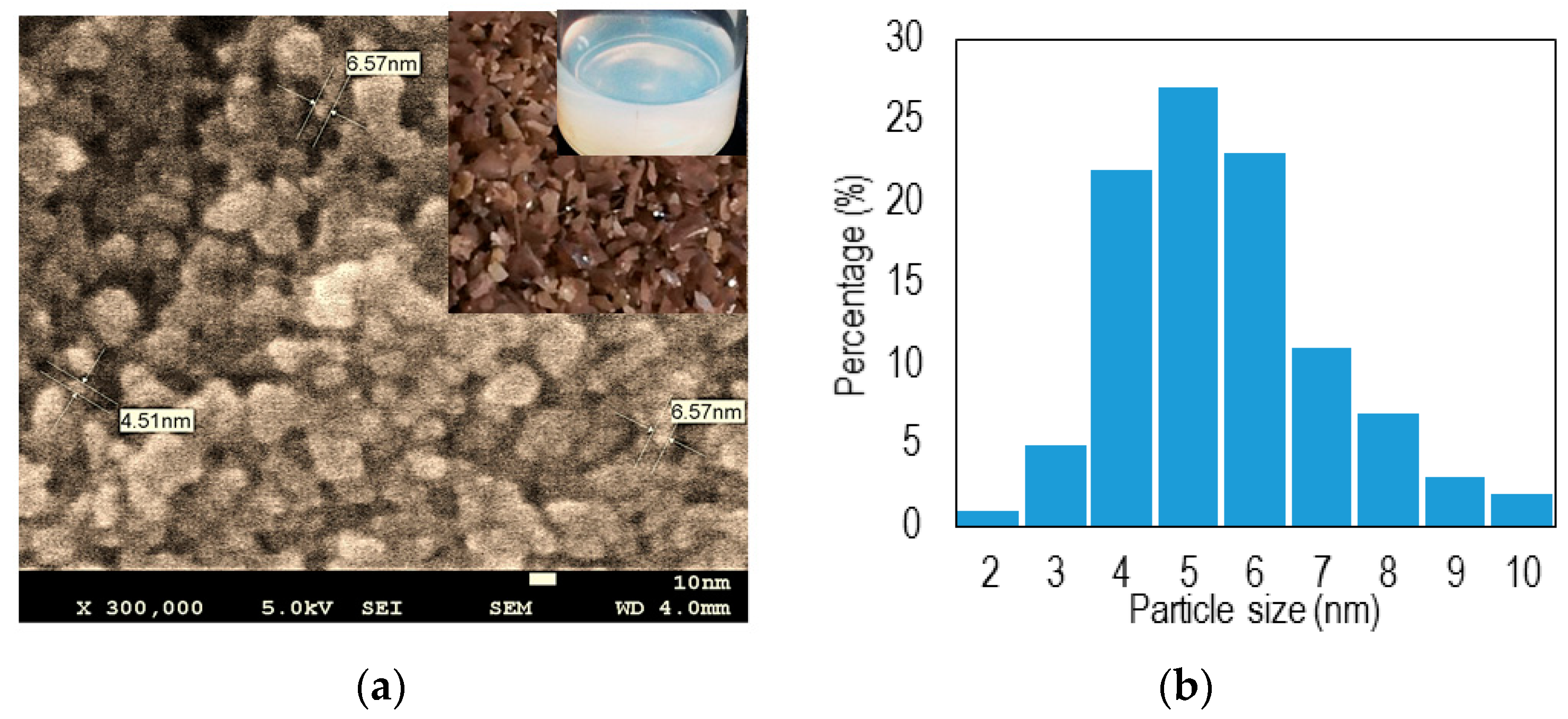
2.3. Field Emission Scanning Electron Microscopy (FESEM)
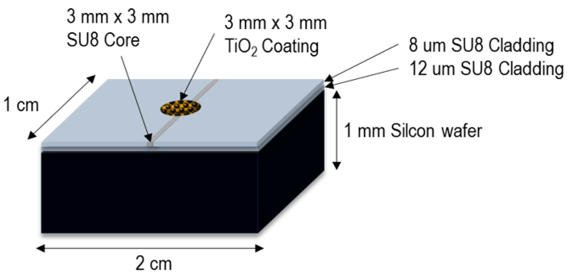
2.4. Device Fabrication

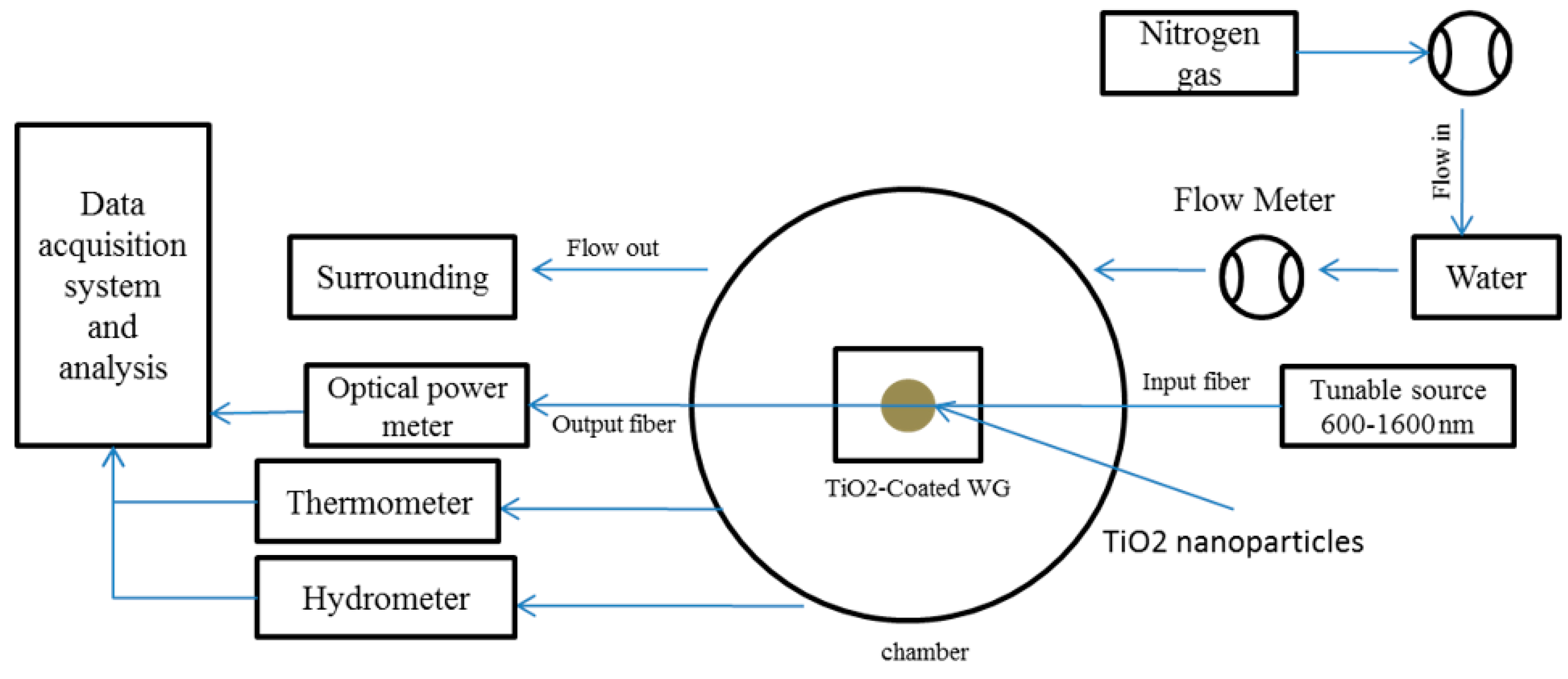
2.5. Humidity Sensing Measurement

3. Results and Discussion

| Concentration | Thickness | Sensitivity | Response Time | Recovery Time |
|---|---|---|---|---|
| (µm) | (dB/%RH) | (s) | (s) | |
| NAT1 | 0.21 | 0.021 | 0.22 | 0.31 |
| NAT2 | 0.53 | 0.12 | 0.61 | 0.75 |
| NAT3 | 0.74 | 0.21 | 0.72 | 0.95 |
| NAT4 | 1.01 | 0.414 | 1.12 | 1.61 |


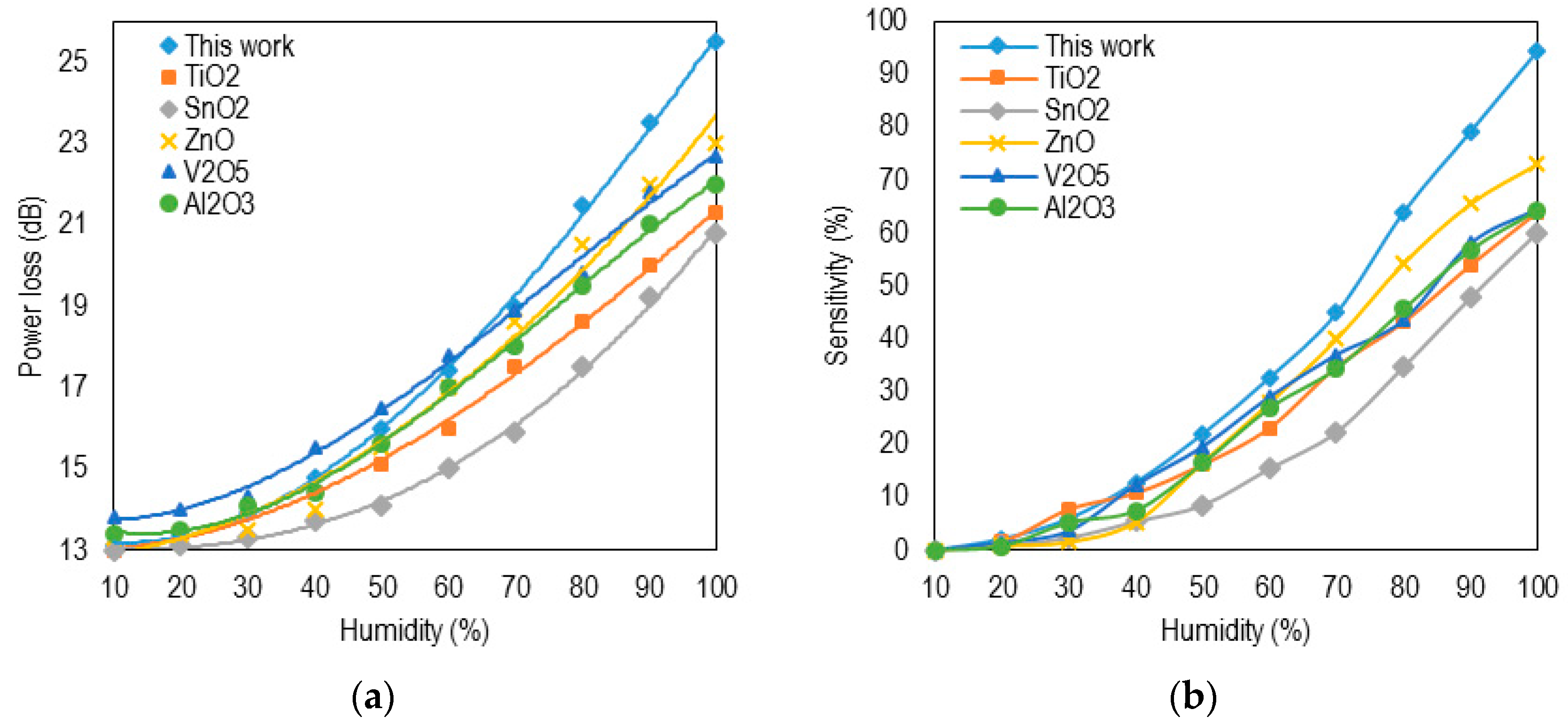
| Reference | Coating Material | Substrate | Range | Sensitivity | Resp. Time |
|---|---|---|---|---|---|
| This work | Nano-anatasTiO2 | SU8 WG | 35%–95% | 0.21 dB/%RH | 0.72 s |
| Lim et al. [24] | Graphene oxide | SU8 WG | 60%–100% | 0.53 dB/%RH | 0.95 s |
| Herrero et al. [25] | TiO2 film | SMF | 0%–15% | 0.49 dB/%RH | - |
| Aneesh et al. [26] | TiO2 nanoparticles | PCS fiber | 24%–95% | 27 mV/%RH | >1 s |
| Corres et al. [7] | SiO2 nanoparticles | SMF | 40%–98% | 0.12 dB/%RH | 0.15 s |
| Aneesh et al. [27] | ZnO nanoparticles | PCS | 4%–96% | 0:0012RH-1 | >1 s |
| Yeo et al. [28] | Polyimide | FBG | 23%–97% | 5.6 dB/%RH | >5 min |
| Gaston et al. [29] | Polyvinyl alcohol film | SMF | 70%–90% | 0.51 dB/%RH | 40 s |
| Tan et al. [30] | Gelatin | LPG | 90%–99% | 1.2 dB/%RH | - |
| Liu et al. [31] | Hydrogel | LPG | 38%–100% | 0.2 nm/%RH | - |
| Vijayan et al. [32] | Co-polyaniline | Optical fiber | 20%–95% | 6 mV/%RH | ~1 min |
4. Conclusions
Acknowledgments
Author Contributions
Conflicts of Interest
References
- Kuang, Q.; Lao, C.; Wang, Z.L.; Xie, Z.; Zheng, L. High-Sensitivity Humidity Sensor Based on a Single SnO2 Nanowire. J. Am. Chem. Soc. 2007, 129, 6070–6071. [Google Scholar] [CrossRef] [PubMed]
- Ren, Y.; Morimile, P.; Petti, L.; Cross, G.H. Optical waveguide humidity sensor with symetric multilayer configuration. Sens. Actuators B 2001, 75, 76–82. [Google Scholar] [CrossRef]
- Lopez-Higuera, J.M.; Rodriguez Cobo, L.; Quintela Incera, A.; Cobo, A. Fiber Optic Sensors in Structural Health Monitoring. J. Lightwave Technol. 2011, 29, 587–608. [Google Scholar] [CrossRef]
- Cocatre-Zilgien, J.H. Aircraft System Monitoring Air Humidity to Locate Updrafts. US Patent US6012675A, 11 January 2000. [Google Scholar]
- Zhang, Y.; Yu, K.; Jiang, D.; Zhu, Z.; Geng, H.; Luo, L. Zinc oxide nanorod and nanowire for humidity sensor. Appl. Surface Sci. 2005, 242, 212–217. [Google Scholar] [CrossRef]
- Ansari, Z.; Karekar, R.; Aiyer, R. Humidity sensor using planar optical waveguides with claddings of various oxide materials. Th. Sol. Film. 1997, 305, 330–335. [Google Scholar] [CrossRef]
- Corres, J.M.; Matias, I.R.; Hernaez, M.; Bravo, J.; Arregui, F.J. Optical fiber humidity sensors using nanostructured coatings of SiO nanoparticles. IEEE J. Sens. 2008, 8, 281–285. [Google Scholar] [CrossRef]
- Borini, S.; White, R.; Wei, D.; Astley, M.; Haque, S.; Spigone, E.; Harris, N.; Kivioja, J.; Ryhänen, T. Ultrafast Graphene Oxide Humidity Sensors. ACS Nano 2013, 7, 11166–11173. [Google Scholar] [CrossRef] [PubMed]
- Stewart, G.; Muhannad, F.A.; Culshaw, B. Sensitivity improvment for evanscent-wave gas sensors. Sens. Actuators B Chem. 1993, 11, 521–524. [Google Scholar] [CrossRef]
- Yeo, T.L.; Sun, T.; Grattan, K.T.V. Fibre-optic sensor technologies for humidity and moisture measurement. Sens. Actuators A Phys. 2008, 144, 280–295. [Google Scholar] [CrossRef]
- Mogera, U.; Sagade, A.A.; George, S.J.; Kulkarni, G.U. Ultrafast response humidity sensor using supramolecular nanofibre and its application in monitoring breath humidity and flo. Sci. Rep. 2014, 4, 1–9. [Google Scholar] [CrossRef] [PubMed]
- Bi, H.; Yin, K.; Xie, X.; Ji, J.; Wan, S.; Sun, L.; Terrones, M.; Dresselhaus, M.S. Ultrahigh humidity sensitivity of graphene oxide. Sci. Rep. 2013, 3, 1–7. [Google Scholar] [CrossRef] [PubMed]
- Ghadiry, M.; Ismail, R.; Naraghi, B.; Taheri Abed, S.; Kavosi, D.; Fotovatikhah, F. A new approach to model sensitivity of graphene-based gas sensors. Semicond. Sci. Technol. 2015, 30, 4. [Google Scholar] [CrossRef]
- Khaledian, M.; Ismail, R.; Saeidmanesh, M.; Ghadiry, M.; Akbari, E. Sensitivity Modelling of Graphene Nanoscroll-Based NO2 Gas Sensors. Plasmonics 2015, 10, 1133–1140. [Google Scholar] [CrossRef]
- Xie, W.; Yang, M.; Cheng, Y.; Li, D.; Zhang, Y.; Zhuang, Z. Optical fiber relative-humidity sensor with evaporated dielectric coating on fiber end-face. Opt. Fiber Technol. 2014, 20, 314–319. [Google Scholar] [CrossRef]
- Lim, W.H.; Yap, Y.K.; Chong, W.Y.; Pua, C.H.; Huang, N.M.; De La Rue, R.M.; Ahmad, H. Graphene oxide-based waveguide polariser: From thin film to quasi-bulk. Opt. Express 2014, 22, 11090–11098. [Google Scholar] [CrossRef] [PubMed]
- Mathew, J. Development of Novel Fiber Optic Humidity Sensors and Their Derived Applications. Master’s Thesis, Dublin Institute of Technology, Dublin, Ireland, 2013. [Google Scholar]
- Wei, N.; Peng, X.; Xu, Z. Underestanding water permeation in graphene oxide membranes. Appl. Mater. Interfaces 2014, 6, 5877–5883. [Google Scholar] [CrossRef] [PubMed]
- Yoon, H.J.; Jun, D.H.; Yang, J.H.; Zhou, Z.; Yang, S.S.; Cheng, M.M.-C. Carbon dioxide gas sensor using a graphene sheet. Sens. Actuators B Chem 2011, 157, 310–313. [Google Scholar] [CrossRef]
- Hashimoto, K.; Irie, H.; Fujishima, A. TiO2 photocatalysis: A historical overview and future prospects. Jpn. J. Appl. Phys. 2015, 44, 8269–8285. [Google Scholar] [CrossRef]
- Shibata, T.; Irie, H.; Hashimoto, K. Enhancement of photoinduced highly hydrophilic conversion on TiO2 thin films by introducing tensile stress. J. Phys. Chem. B 2003, 107, 10696–10698. [Google Scholar] [CrossRef]
- Kim, I.-D.; Rothschild, A.; Lee, B.H.; Kim, D.Y.; Jo, S.M.; Tuller, H.L. Ultrasensitive chemiresistors based on electrospun TiO2 nanofibers. Nano Lett. 2006, 6, 2009–2013. [Google Scholar] [CrossRef] [PubMed]
- Manera, M.; Montagna, G.; Ferreiro-Vila, E.; González-García, L.; Sánchez-Valencia, J.; González-Elipe, A.; Cebollada, A.; Garcia-Martin, J.M.; García-Martín, A.; Armelles, G. Enhanced gas sensing performance of TiO2 functionalized magneto-optical SPR sensors. J. Mater. Chem. 2011, 21, 16049–16056. [Google Scholar] [CrossRef] [Green Version]
- Lim, W.H.; Yap, Y.K.; Chong, W.Y.; Ahmad, H. All-Optical Graphene Oxide Humidity Sensors. Sensors 2014, 14, 24329–24337. [Google Scholar] [CrossRef] [PubMed]
- Alvarez-Herrero, A.; Guerrero, H.; Levy, D. High-sensitivity sensor of low relative humidity based on overlay on side-polished fibers. IEEE J. Sens. 2004, 4, 52–56. [Google Scholar] [CrossRef]
- Aneesh, R.; Khijwania, S.K. Titanium dioxide nanoparticle based optical fiber humidity sensor with linear response and enhanced sensitivity. Appl. Opt. 2012, 51, 2164–2171. [Google Scholar] [CrossRef] [PubMed]
- Aneesh, R.; Khijwania, S.K. Zinc oxide nanoparticle based optical fiber humidity sensor having linear response throughout a large dynamic range. Appl. Opt. 2011, 50, 5310–5314. [Google Scholar] [CrossRef] [PubMed]
- Yeo, T.; Sun, T.; Grattan, K.; Parry, D.; Lade, R.; Powell, B. Characterisation of a polymer-coated fibre Bragg grating sensor for relative humidity sensing. Sens. Actuators B Chem. 2005, 110, 148–156. [Google Scholar] [CrossRef]
- Gaston, A.; Lozano, I.; Perez, F.; Auza, F.; Sevilla, J. Evanescent wave optical-fiber sensing (temperature, relative humidity, and pH sensors). IEEE J. Sens. 2003, 3, 806–811. [Google Scholar] [CrossRef]
- Tan, K.M.; Tay, C.M.; Tjin, S.C.; Chan, C.C.; Rahardjo, H. High relative humidity measurements using gelatin coated long-period grating sensors. Sens. Actuators B Chem. 2005, 110, 335–341. [Google Scholar] [CrossRef]
- Liu, Y.; Wang, L.; Zhang, M.; Tu, D.; Mao, X.; Liao, Y. Long-period grating relative humidity sensor with hydrogel coating. IEEE Photonics Technol. Lett. 2007, 19, 880–882. [Google Scholar] [CrossRef]
- Vijayan, A.; Fuke, M.; Hawaldar, R.; Kulkarni, M.; Amalnerkar, D.; Aiyer, R. Optical fibre based humidity sensor using co-polyaniline clad. Sens. Actuators B Chem. 2008, 129, 106–112. [Google Scholar] [CrossRef]
© 2015 by the authors; licensee MDPI, Basel, Switzerland. This article is an open access article distributed under the terms and conditions of the Creative Commons by Attribution (CC-BY) license (http://creativecommons.org/licenses/by/4.0/).
Share and Cite
Ghadiry, M.; Gholami, M.; Choon Kong, L.; Wu Yi, C.; Ahmad, H.; Alias, Y. Nano-Anatase TiO2 for High Performance Optical Humidity Sensing on Chip. Sensors 2016, 16, 39. https://doi.org/10.3390/s16010039
Ghadiry M, Gholami M, Choon Kong L, Wu Yi C, Ahmad H, Alias Y. Nano-Anatase TiO2 for High Performance Optical Humidity Sensing on Chip. Sensors. 2016; 16(1):39. https://doi.org/10.3390/s16010039
Chicago/Turabian StyleGhadiry, Mahdiar, Mehrdad Gholami, Lai Choon Kong, Chong Wu Yi, Harith Ahmad, and Yatima Alias. 2016. "Nano-Anatase TiO2 for High Performance Optical Humidity Sensing on Chip" Sensors 16, no. 1: 39. https://doi.org/10.3390/s16010039