Sol-Gel Deposition of Iridium Oxide for Biomedical Micro-Devices

Abstract
: Flexible iridium oxide (IrOx)-based micro-electrodes were fabricated on flexible polyimide substrates using a sol-gel deposition process for utilization as integrated pseudo-reference electrodes for bio-electrochemical sensing applications. The fabrication method yields reliable miniature on-probe IrOx electrodes with long lifetime, high stability and repeatability. Such sensors can be used for long-term measurements. Various dimensions of sol-gel iridium oxide electrodes including 1 mm × 1 mm, 500 μm × 500 μm, and 100 μm × 100 μm were fabricated. Sensor longevity and pH dependence were investigated by immersing the electrodes in hydrochloric acid, fetal bovine serum (FBS), and sodium hydroxide solutions for 30 days. Less pH dependent responses, compared to IrOx electrodes fabricated by electrochemical deposition processes, were measured at 58.8 ± 0.4 mV/pH, 53.8 ± 1.3 mV/pH and 48 ± 0.6 mV/pH, respectively. The on-probe IrOx pseudo-reference electrodes were utilized for dopamine sensing. The baseline responses of the sensors were higher than the one using an external Ag/AgCl reference electrode. Using IrOx reference electrodes integrated on the same probe with working electrodes eliminated the use of cytotoxic Ag/AgCl reference electrode without loss in sensitivity. This enables employing such sensors in long-term recording of concentrations of neurotransmitters in central nervous systems of animals and humans.1. Introduction
Implantable electrochemical sensors have emerged as one of the more attractive means for in situ sensing and monitoring biological conditions such as pH, pO2, and pCO2, physiological signals such as ECG, EEG, and biological analytes such as glucose, lactate, uric acid and neurotransmitters [1–7]. There is a growing interest in miniaturizing the sensors for long-term recording. Several widely acknowledged advantages of smaller sensors include minimization of local tissue damage, reduction of inflammation, and improvement of large-scale integration and spatial resolution [3,4,8]. Advancements in microelectromechanical system (MEMS) and micromachining technologies have played a substantial role in the quest for miniaturizing implantable sensors with batch production. Recent fabrication technologies also allow integrating multiple microelectrode arrays (MEAs) on different substrates such as silicon, ceramic, glass and polyimide [5,9–13].
Reference electrodes (RE), the mandatory parts of the electrochemical sensors, are important to provide reference points for measurement [14–16]. Most biochemical sensors utilize dedicated silver/silver chloride (Ag/AgCl) wires as the REs in in vivo experiments [3,17]. The Ag/AgCl wires are normally placed apart with a superfluous distance from the sensing sites due to difficulties of implantation processes [17]. Thus, sufficient ionic contact between the Ag/AgCl wires and the working electrode (WE) is required to guarantee a valid measurement of the sensor. Additionally, the Ag/AgCl RE is inconvenient, for example, in long-term experiments in which the sensor might be anchored to a mammalian organ and the additional electrodes would induce more injuries to tissues. Excessive noises are also predicted with the distant RE. Therefore, it is compelling that MEAs integrate both reference and working electrodes on the same probe [17].
On-probe planar Ag/AgCl reference electrodes have been considered in our previous work [7,18]. However, many issues have been identified in biological applications. First, the traditional laboratory fabrication method using electroplating of bulk silver in a saturated chlorine solution has low throughput and is unrepeatable [19]. Second, the fabricated Ag/AgCl films easily delaminate and dissolve in long-term experiments, especially in biological environments with less chloride ions [16,19–21]. Third, bulk and nano-structured silver electrodes have demonstrated cytotoxicity to living tissues in both acute and long-term experiments [22,23]. Iridium oxide (IrOx)-based electrodes have emerged as an attractive alternative for REs due to their unique properties. IrOx has been widely accepted in neuroscience applications, especially electrophysiological recording and stimulation because of its high charge density, biocompatibility, and corrosion resistance in electrolyte solutions [24–27]. In addition, IrOx electrodes, owing to their stable mechanical properties on both rigid and flexible electrodes, have been promisingly used for long-term experiments [17]. Although the electrode potential of IrOx is pH-dependent, it has been proven that the potential varies within a small dynamic range in biological environments where the change is less than 0.8 pH units [17,28,29]. Thus, we proposed to utilize IrOx electrodes as reference electrodes for biomedical recording; and we refer to them as pseudo-reference electrodes [30].
IrOx could be fabricated by different methods, such as directly sputtering using an IrOx target, thermal oxidation of iridium, anodic electrodeposition of IrOx, and sol-gel dip-coating. Sputtering and thermal oxidation of iridium are not preferable due to cost of materials needed. Electrodeposition has been well-developed and allows depositing hydrated IrOx onto micro-scale electrodes [17,31]. However, the main shortcomings of the electrodeposited IrOx films are low adhesion to their substrates and delamination in biological environments [32,33]. In addition, an issue of over-electrodeposition yielding conductive IrOx dendrites outside of the electrode areas could consequently cause cross-talk between electrodes in the MEA. Finally, higher dependence of such hydrated IrOx to pH change endowing a super-Nernst response of 66–72 mV/pH [33] is not desirable for pseudo-REs.
Sol-gel dip-coating has been implemented to fabricate IrOx electrodes for miniature pH sensor arrays [8,18,34]. The method yields anhydrous IrOx films exhibiting the Nernst response around 56 mV/pH, which is lower than that of the electrodeposited IrOx [8,18]. Additionally, the IrOx film becomes stable and highly adhesive to the substrates after heat-treatment [18]. In this work, we investigated the implementation of the sol-gel-based IrOx films for pseudo-REs. The previous fabrication method introduced a thick SU-8 photoresist mask to precisely and selectively coat the gel solution on pre-defined electrodes [18]. However, the sacrificial layers degraded and became hard to remove after the heat treatment at 300 °C, thus it was difficult to apply the process for small electrode sites. Utilizing sol-gel processes with two-step heat treatment could prevent the aforementioned problem with the sacrificial layers. While the first step of pre-heating at a low temperature was aimed at dehydrating the sol-gel solution, the second one of curing at higher temperature was applied to yield a more adhesive amorphous IrOx thin film. The sacrificial photoresist mask was stripped off between these two steps. The lower temperature of the dehydration step allowed easy removal of the SU-8. Thus, it became possible to fabricate miniature electrodes with different dimensions on both rigid and flexible substrates.
In this work, we implemented the modified sol-gel deposition to fabricate miniature IrOx electrodes. Various IrOx electrode designs have been fabricated on flexible substrates targeting biological applications. The pH-dependence of these electrodes was investigated. Long-term stability was examined in in vitro experiments by immersing the electrodes in acidic, alkaline and neutral solutions. The sol-gel-based IrOx electrode was integrated as the pseudo-RE of a dopamine (DA) sensor. The simple, cost-effective and high-throughput manufacturing processes yielded the DA sensor with many advantages such as high stability, reproducibility and high resolution.
2. Materials and Methods
2.1. Sensor Fabrication
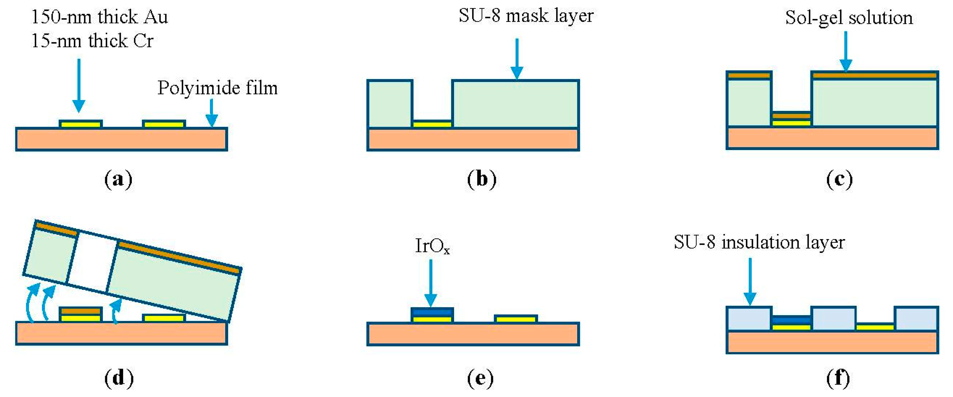
Microelectrodes of different dimensions were fabricated on a 125-μm polyimide flexible substrate. The substrate was cleaned with acetone and rinsed before applying 15-min heat treatment at 100 °C. Photolithography was carried out to pattern the microelectrodes of different sizes including 1 mm × 1 mm, 500 μm × 500 μm, and 100 μm × 100 μm for investigation. This was followed by deposition of layers of 15-nm thick chromium and 150-nm thick gold using an e-beam evaporator, as depicted in Figure 1a. Lift-off was carried out to release sacrificial layers revealing the micro-patterns. Next, the negative-tone photoresist SU-8 (MicroChem, Newton, MA, USA) was spin-coated to form a mask layer. The thicker the SU-8 layer was, the easier it was to peel-off later. However, it was tedious to handle the device during fabrication processes. Thus, the thickness of the sacrificial mask layer was chosen as 50 μm. Different types of SU-8 including SU-8-2025, SU-8-50, and SU-8-100 were tested. Based on our experimental data, we chose SU-8-50 to employ in the 50-μm thick mask, as illustrated in Figure 1b. The sample was then coated with an iridium chloride sol-gel solution (Figure 1c). The preparation of the solution and coating processes are described in Section 2.2. Figure 1d illustrates the peeling-off process after the first heat treatment step. The second heat treatment at 300 °C was carried out to form a thin layer of iridium oxide (Figure 1e). In the final step, a 5-μm thick SU-8-5 layer was coated as an insulation layer covering the entire microelectrode except the sensing areas and connection pads, as shown in Figure 1f. Finally, copper wires from external measurement circuits were connected to the pads using silver epoxy.
2.2. Sol-Gel Deposition
The sol-gel solution was mixed according to the recipe given in [8] by dissolving 0.5 g iridium chloride in 21 mL of ethanol (95%, Sigma-Aldrich, St. Louis, MO, USA) and 5 mL of acetic acid solution (99.7%, MG Scientific, Pleasant Prairie, WI, USA). The solution was stirred by a magnetic rod for one hour. Dip-coating process was carried out by immersing the entire substrate in the sol-gel solution. The SU-8 mask exposed only the sensing area of the micro-electrodes to the sol-gel solution for coating. After immersing the electrodes in the sol-gel solution for a few minutes, the whole substrate was drawn out with a withdraw rate of 2 cm/min using a dip-coating apparatus [8,34]. This withdraw rate was experimentally shown to provide good film uniformity. The film quality and thickness showed significant improvement when the dipping process was repeated five times.
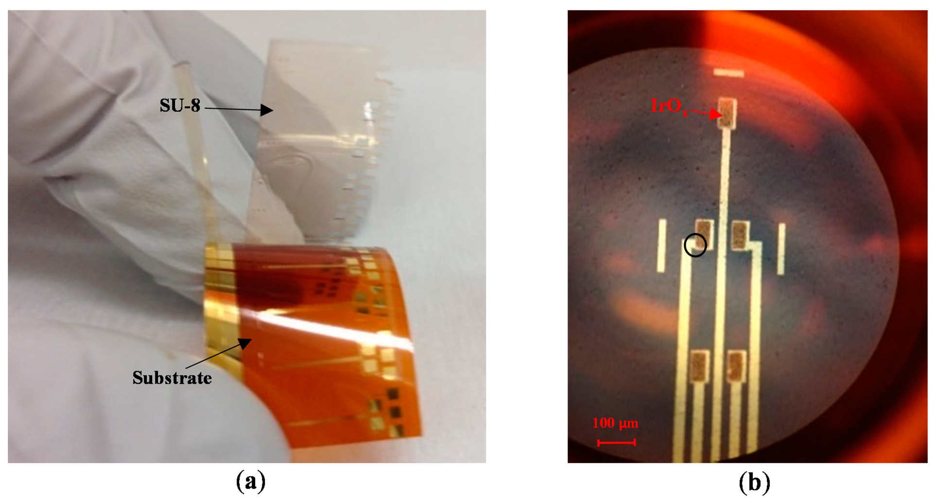
After the sol-gel dip coating step, the sample was subjected to heat treatment to generate IrOx from iridium chloride. First, a heat treatment step at 100 °C for 15 min dehydrated the sol-gel solution. Afterwards, the SU-8 sacrificial layer was peeled-off by bending the flexible substrate, as shown in Figure 2a. It should be noted that the adhesion of SU-8 to the substrate is poor; therefore, the sacrificial mask was automatically detached by mechanical stresses. Next, a second heat treatment step was carried out with the samples in an oven. The heating profile was: (1) ramp-up to 300 °C at a rate of 2 °C/min; (2) soak at 300 °C for four hours; and then (3) ramp-down to 25 °C at a rate of 1 °C/min. This step completed conversion of hydrated iridium chloride into iridium oxide, as illustrated by color change from brown to blue in Figure 1e. The optical microscope photo in Figure 2b shows an MEA with five electrodes. Each electrode has opening area of 50 × 100 μm2 and was coated with IrOx.
2.3. Material Characterization
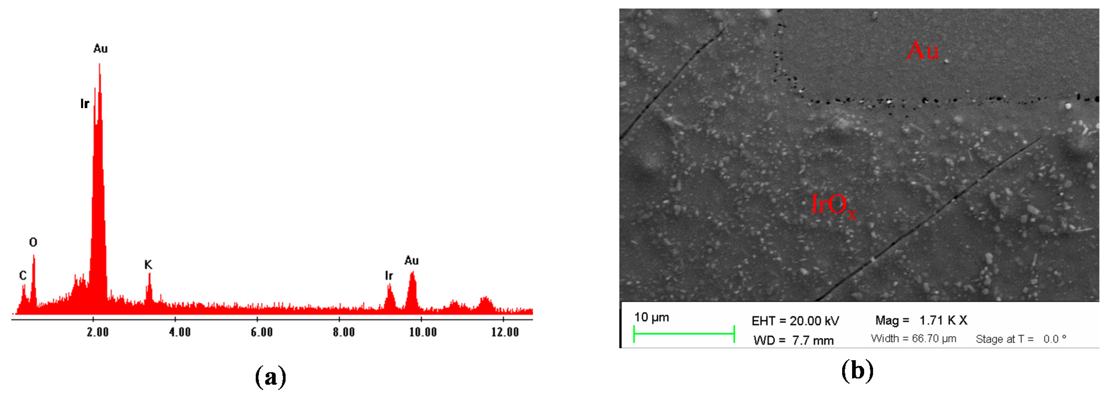
Iridium oxide fabricated by sol-gel deposition was characterized by energy dispersive spectroscopy (EDS). Figure 3a shows the material composition on the surface of the electrode after sol-gel deposition. There were clear peaks of different materials including Ir, Au, C, O and K with composition percentages of 18.19%, 47.18%, 17.69%, 15.19% and 1.74%, respectively. The presence of carbon element was due to polyimide substrate while there was small amount of potassium due to contamination. Scanning electron microscopy was also utilized to examine of the surface morphologies of the micro-electrode. The composition of the film is similar to the one made by one-step sol-gel heat treatment. Figure 3b shows the surface of the electrode coated with IrOx, which was rougher than the one in the Au area. Micro-scale porous structures of IrOx were observed. The porous structures with a high surface-to-volume ratio could affect electrochemical properties of the bulk IrOx such as the ion exchange, rate to reach the equilibrium point of reversible reaction, or the amount of charge storage [18].
3. Experiments and Results
Typical electrochemical sensors have 3-electrode configuration with a working electrode (WE), a reference electrode (RE) and an auxiliary or counter electrode (CE) [35,36]. Applications using micro-electrochemical sensors could eliminate the CE since output signals of the sensor are small [3,35,36]. Among many electrochemistry methods, amperometric sensors require a fixed bias voltage applied between their WEs and REs. Since the output signals of the miniature amperometric sensors are in the range of picoamps, the signals could be affected by minute changes of the bias voltage. Consequently, one of the important characters of the ideal RE is to provide a constant open-circuit potential regardless of electrolyte solutions. The change of IrOx electrode potential obeys its pH sensitivity. However, pH variations are narrowly limited in many in vivo biological mechanisms, especially targeted neurotransmitter concentration changes due to neuro-activities [17,28,29]. Obviously a RE with less pH dependence is more preferable. Therefore, it is important to understand the pH dependency of the sol-gel-based IrOx.
3.1. Characterization of Sol-gel-Based pH Electrodes
The two-step sol-gel fabrication process allows producing miniature IrOx-based electrodes. Three different electrode dimensions, including 1 mm × 1 mm, 500 μm × 500 μm and 100 μm × 100 μm, were designed. Four electrodes of each type were fabricated and calibrated in order to demonstrate the reproducibility of the fabrication processes. Open-circuit potentials of the IrOx micro-electrodes were measured versus a standard Ag/AgCl RE (Basi, West Lafayette, IN, USA) in different standard buffer solutions pH = 4, 7 and 10 (Mettler Toledo, Columbus, OH, USA). The open-circuit potential (E) of IrOx electrode in the half-reaction (1) is governed by the Nernst Equation (2):
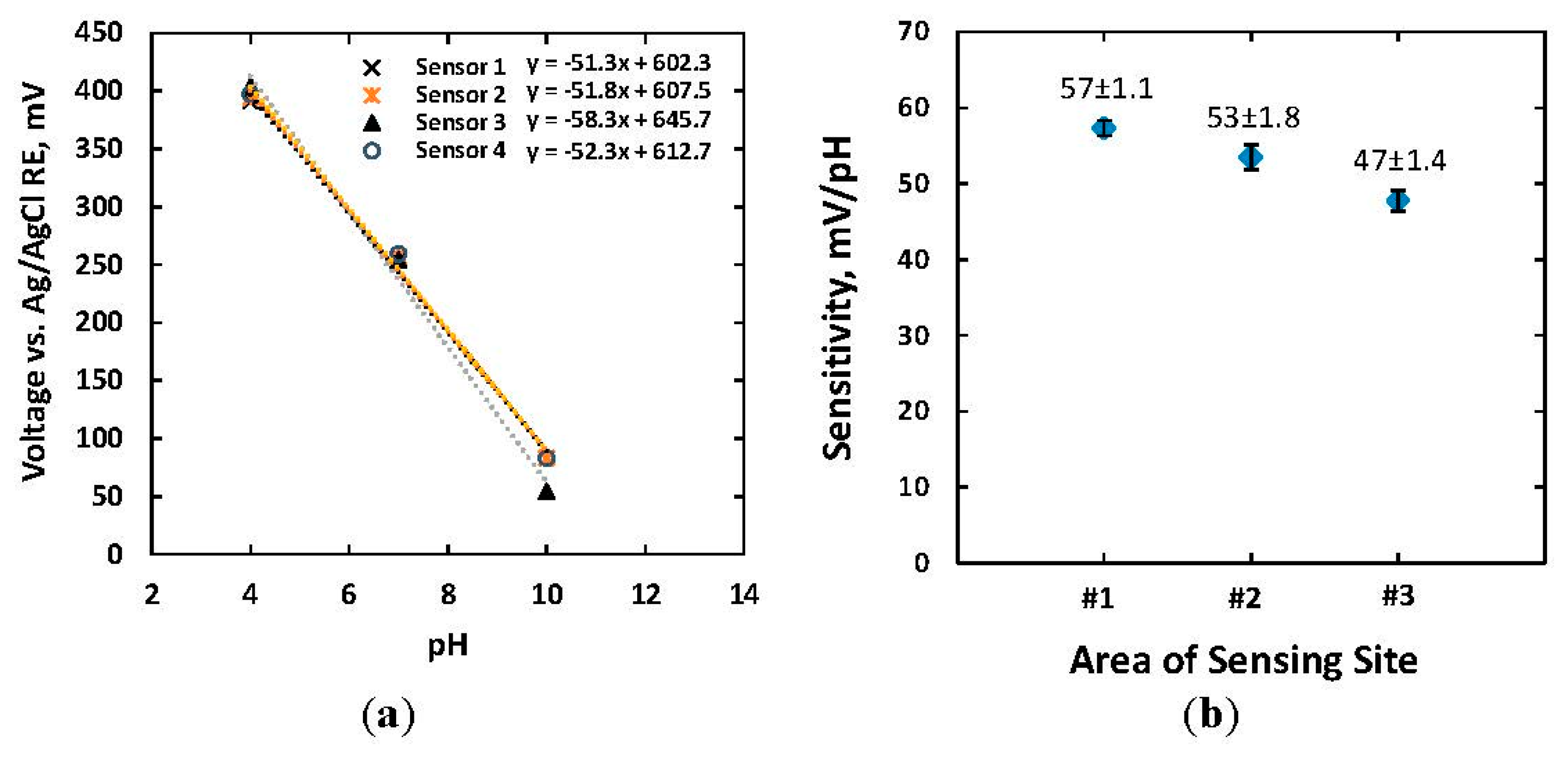
Figure 4a shows the responses of four IrOx electrodes, each of 500 μm × 500 μm size, to standard buffer solutions. The absolute slopes of pH responses were in a range of 51.3–58.3 mV/pH with a linear regression of approximately 0.993, which indicated a Nernst response according to Equation (2). Standard error of the means (SEMs) of the measurements were 5.0 mV, 1.4 mV and 6.9 mV when measuring with commercial buffer solutions of pH = 4, 7, and 10, respectively. Less SEM in the case of the solution pH = 7 indicated higher reproducibility of pH measurements in neutral solutions. The measured pH sensitivities of IrOx-based electrodes with various dimensions are shown in Figure 4b. Four electrodes of the same size were measured to obtain statistical variations. There were slight differences in sensitivity for electrodes size of 1 mm × 1 mm and 500 μm × 500 μm, which were 57 ± 1.1 and 53 ± 1.8 mV/pH. The smaller electrodes with a size of 100 μm × 100 μm exhibited less pH dependence of 47 ± 1.4 mV/pH. The relationship between electrode potential and electrode size has not been well-studied yet the Nernst equation does not regard the sensor size. However, the empirical study showed that the smaller electrode possessed less sensitivity. There are two possible reasons for the aforementioned phenomenon. Firstly, the reduced sensitivity of the miniature electrode might relate to the double layer region and diffusion layer formed around the finite space of the microelectrode in electrolyte solutions [35]. The ratio between the thickness of the diffusion layer and physical dimension of the electrode in such case became larger [35]. Bard et al. demonstrated that the profile of steady-state ion concentration was proportional to the inverse of distance from the electrode surface [35]. In other words, the local ion concentration and distribution of proton H+ near the surface of the electrodes pH|x=0 became complex and was adjusted from bulk ion concentration. Thus, the microelectrode showed less sensitivity to pH change of the solution. Secondly, a higher impedance in the smaller microelectrode (∼MΩ) which was comparable to the input impedance of the measurement system reduced the measured voltage from the actual open-circuit potential. An ultra-high input impedance will be needed in such cases.
With a pH sensitivity of 47–57 mV/pH for our miniature-dimension electrodes, the changes of pH in a typical biological environment within a range of 7.0–7.4 corresponded to a maximum variation of around 20 mV. Therefore, the variation in the open-circuit electrode potentials due to pH changes will be negligible compared to the applied bias voltage of 0.7 V in dopamine measurements.
3.2. Long-Term Stability of the IrOx Electrodes
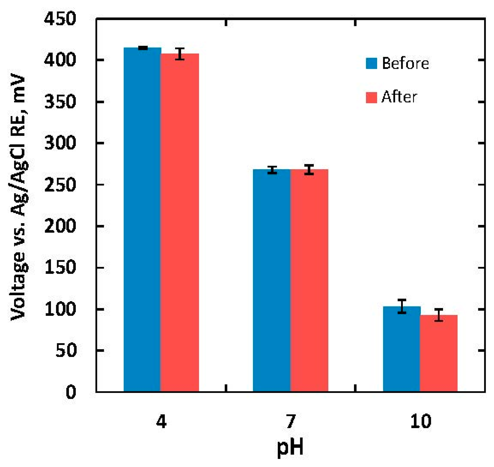
Longevity of the reference electrodes is critical in long-term electrochemical recording. Since we target biomedical applications, open-circuit potentials of the IrOx electrode versus an Ag/AgCl RE were examined in two different tests. First, the sensor was tested in a scenario in which the electrode surface first encountered a new biological environment during implantation. The pH sensitivity of the IrOx electrode was characterized when immersed in a 0.05-M phosphate buffered solution (PBS) for 36 h. The PBS solution was chosen since it is a commonly used isotonic solution with physiological pH. An IrOx electrode with a size of 500 μm × 500 μm was fabricated. Figure 5 shows potential responses of the IrOx electrode with different buffer solutions before and after immersing the electrode in the PBS solution.
The measurements were repeated three times. The error bars in Figure 5 indicated the measurement variations. The measured sensitivities before and after the 36-hour experiment were 51.8 and 52.4 mV/pH, respectively. The longevity was then further characterized to verify the performance of sol-gel-based IrOx− electrodes in long-term implantable experiment. The sensors were immersed in different solutions including hydrochloric acid, fetal bovine serum (FBS), and an alkaline buffer solution. The choice of hydrochloric acid was to demonstrate that the sensor could function in a highly acidic biological environment such as inside the stomach with pH of around 2. The FBS solution was chosen because it is commonly used in vitro as serum-supplement for cell culture media. Another purpose for the experiment with FBS was to examine how the biofouling effect would affect performance of the sensing film. The alkaline buffer solution of pH = 10 (Mettler Toledo), consisting of sodium hydroxide, potassium chloride and boric acid, was chosen to investigate if the film would be affected in an alkaline environment, and if abundant sodium and potassium ions, which are the most common ions in the biological environment, would affect the sensor lifetime.
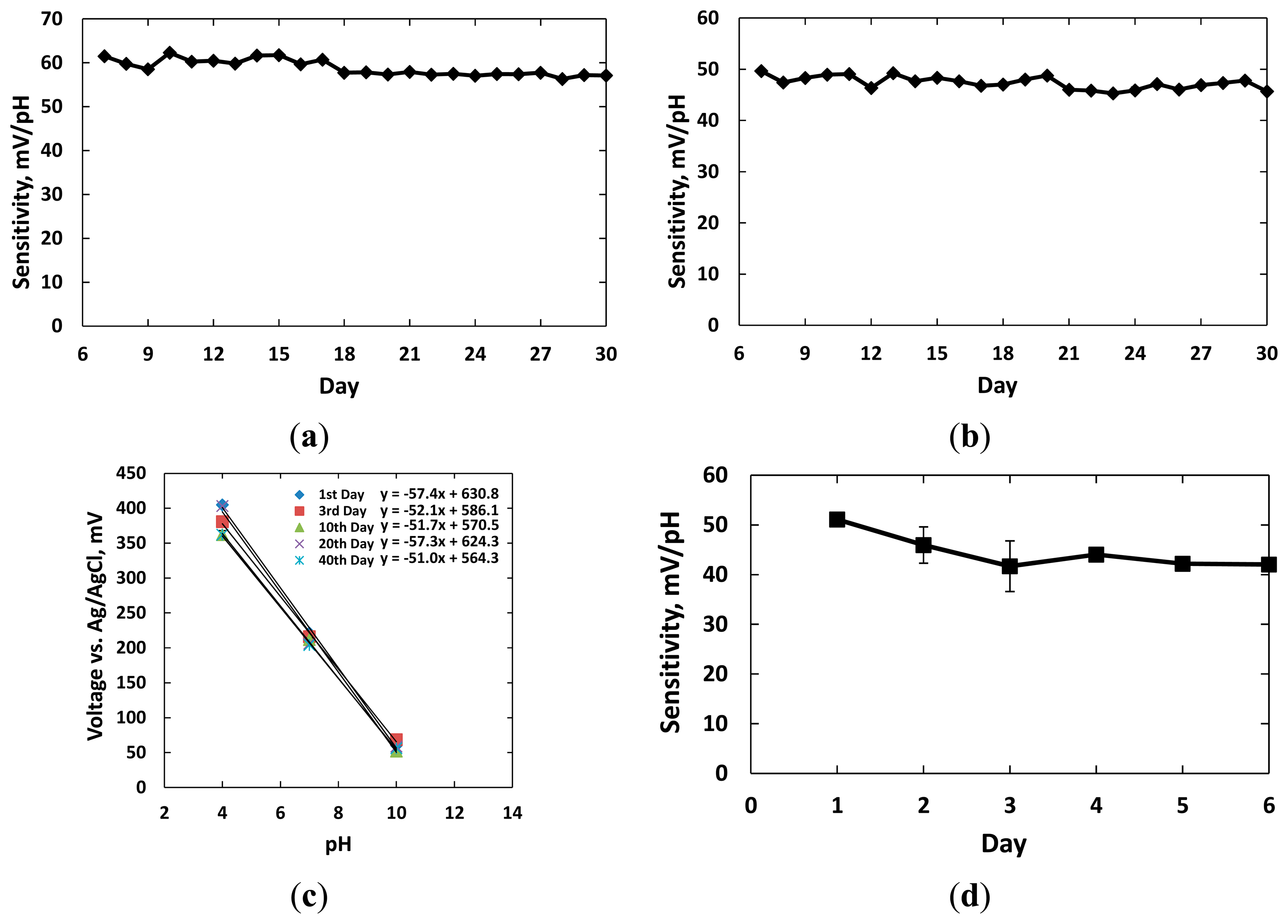
Twelve sensors with dimension of 1 mm × 1 mm were classified into four groups for the experiments. Three groups were kept in the individual beakers with hydrochloric acid (controlled at pH = 2), alkaline buffer solution (pH = 10), and standard tissue culture media RPMI 1640 supplemented with 10% FBS (Fisher Scientific, Pittsburgh, PA, USA). The electrodes in the fourth group were kept dry in air for comparison. The sensors of each group were tested daily with standard buffer solutions pH = 4, 7, 10 to find the sensitivity curves. After the tests, the sensors were replaced in their original setups. The experiments were carried out for 30 days. Figure 6 shows the sensitivity results in the four different environments.
Figure 6a shows the responses of three sensors kept in the acidic solution with pH = 2 over 30 days. The measurements were conducted after the 6th day. The pH sensitivities of three sensors remained at 57.3 ± 0.6 mV/pH after the 30th day. Standard deviation of the calibration data over 30 days was less than 1.9 mV/pH, which reflected stable performance of these sensors. Figure 6b shows the responses of three sensors kept in the alkaline solution with pH = 10. We noticed that the SU-8 insulation layer visually degraded and wrinkled while soaked in the alkaline solution after five days; however, the experiments were continued. The sensitivities of three sensors in this group were recorded at 48.1 ± 0.55, 47.7 ± 0.61 and 48.0 ± 0.66 mV/pH after 30 days. The reduction in sensitivities was probably due to residues of alkaline solution and hydroxyl ions deeply absorbed and retained at the micro- and nanoscale IrOx pores [8]. The ion exchanges decreased diffusion processes and also altered equilibrium points from the double layer region when new solutions were tested. Both effects changed the electrode potentials of the sensors.
Figure 6c shows the sensitivities of three sensors kept in the FBS solution for 40 days. The average measured sensitivities were 57.4 ± 0.3, 52.1 ± 0.6, 51.7 ± 0.9, 57.3 ± 0.6, and 51.0 ± 0.5 mV/pH on the 1st, 3rd, 10th, 20th and 40th days, respectively. Experiment data showed that the pH responses of these three sensors to the buffer solution pH = 7 decreased 17 mV over 40 days. This change in electrode potentials of the sol-gel IrOx electrodes were negligible compared to the applied bias voltage for amperometric sensors. Therefore, it is promising to use them as pseudo-reference electrodes in biological applications.
We noticed the pH sensitivity was reduced and remained at 42.0 ± 0.6 mV/pH when the sensor were kept dry within 6 days of fabrication, as shown in Figure 6d. The sensor sensitivity recovered to the Nernst performance after immersing in an aqueous solution for three hours. The highest SEM in three measurements of 3.65 mV/pH was higher than the ones for the other electrodes in solutions. The lower sensitivity and higher variations in responses were probably due to dehydration and air filling up the micro- and nanoscale pores in the IrOx film surface. In other words, longer time was needed for the equilibrium points of the redox reaction to reach after ions exchange between solution and surface particles. Therefore, we concluded that the IrOx-based electrodes should be preserved or presoaked in a hydrated condition such as PBS solution after fabrication in order to provide stable potentials. Identical conditions are also suggested for most commercially available reference electrodes.
3.3. IrOx-Based Pseudo-Reference Electrodes
Dopamine is one of the most ubiquitous neurotransmitters of the mammalian central nervous systems (CNS). Recording of dopamine concentration in the CNS could help doctors to understand many diseases such as Parkinson's disease, Alzheimer's diseases and neurodegenerative diseases [4,9,10]. Amperometry and cyclic voltammetry methods have been commonly used to detect dopamine [37,38]. While the amperometry method utilizes a fixed bias voltage, the cyclic voltammetry method sweeps the bias voltage. The applied voltages initiate redox reaction following Equation (3). If we denote dopamine (C8H11NO2) as DA and C8H11N(OH)2 as DAH2, then Equation (3) is reduced to Equation (4). Current measurement recorded by amperometry and cyclic voltammetry methods follow the Butler-Volmer Equation (5) [35,37]:
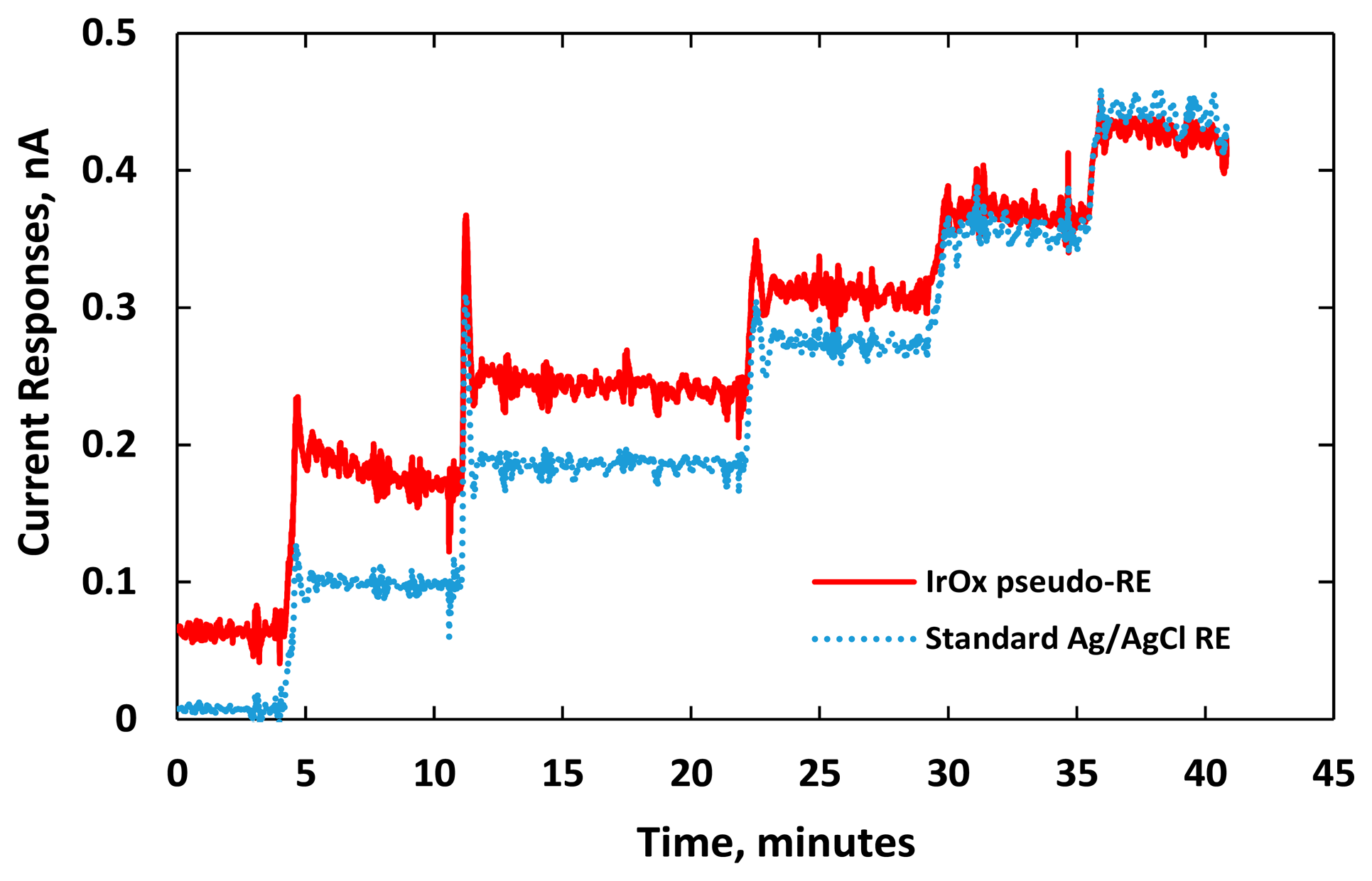
Figure 7 shows distinct responses to each increment of DA concentration. We noticed electrical current overshoots on both sensors as soon as the DA was added. The phenomenon happened in the transient period due to artifact noises or a local rise of ion concentration around the electrode [3,35,39]. The transient time between the adding of DA and the stable current response was short for both sensors demonstrating fast sensing electrode performance. Noises recorded by both sensors were also similar. The current responses damped down and reached their steady state after one minute.
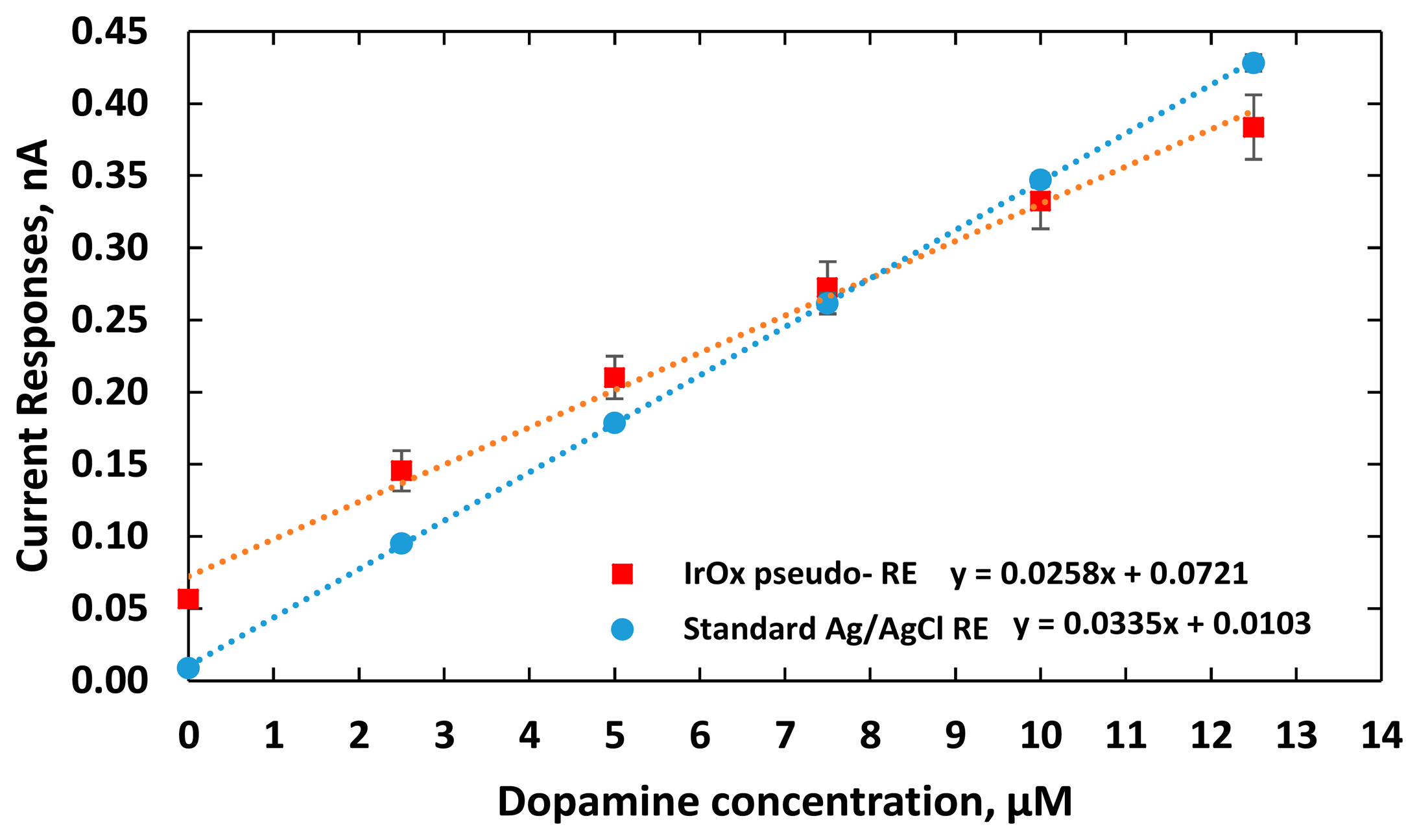
The experiments were repeated three times recording electrical currents at various DA concentrations. As shown in Figure 8, the sensitivities of the two DA sensors were measured as 25.8 ± 0.07 and 33.5 ± 0.01 pA/μM, for using the IrOx pseudo-RE and a standard Ag/AgCl RE, respectively. Due to the fact that the highly electroactive IrOx has fast reversible redox reactions or a larger rate of reaction k0 [40,41], the DA sensor using the IrOx pseudo-RE has an output with higher baseline current. The measurements also indicated that the sensor exhibited less sensitivity than the one with a standard reference probe. It should be noted that the pseudo-RE has a miniature size (50 μm × 100 μm). According to Equation (5), its sensitivity is expected to be less due to its higher impedance. Besides the electrode dimensions, to optimize the sensitivity, other factors should also be considered including spacing between the WE and RE, acquisition instrumentation configurations (input impedance and gain) and working electrode materials.
3.4. IrOx-Based Working Electrodes
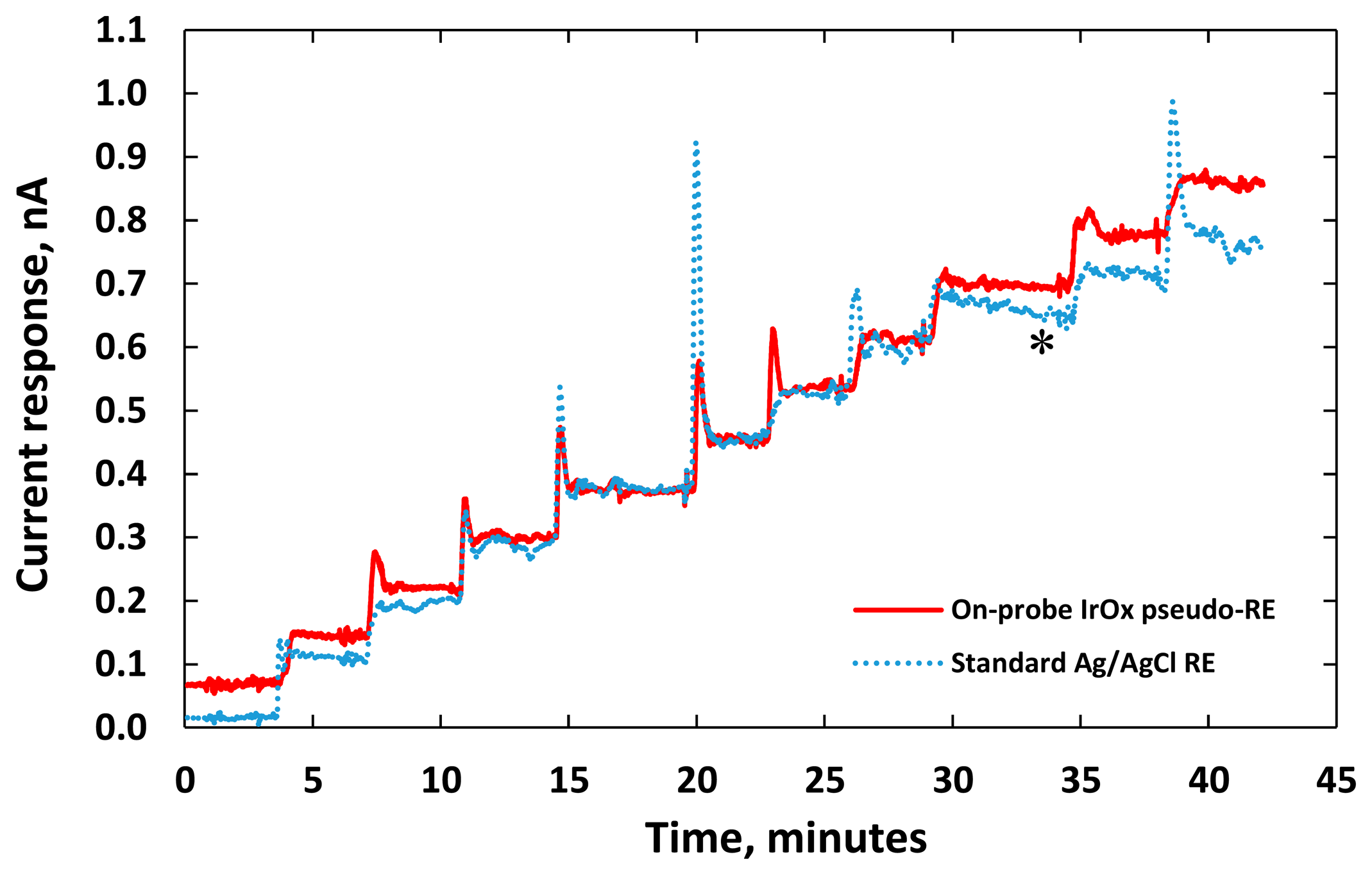
We have also investigated the possibility of implementing IrOx electrodes for both working and reference electrodes. Dopamine sensors with the WE and RE on the same probe were fabricated with the same sol-gel batch processes. Each electrode had a size of 50 μm × 100 μm. A bias voltage of 0.7 V was applied between the two electrodes. The tests were carried out by incrementally adding DA to the PBS solution, as before. At the same time, another DA sensor consisting of a gold WE and a standard Ag/AgCl RE was placed in the beaker to compare results.
Figure 9 shows electric current responses of these two DA sensors while incremental adding 2.5-μM DA to raise the concentration of the PBS solution. The performance of the DA sensor with integrated IrOx WE and RE is similar to the one with a gold WE and an external Ag/AgCl reference probe. When the concentration of DA increased above 30 μM, the current responses of the DA sensor with the gold WE degraded. The degraded performance (blue curve) is indicated by * in Figure 9. The degradation commonly happened with micro-electrodes due to accumulation of the byproduct (DAH2) generated by the redox reaction within the micro-scale sensing area [9,42]. This issue became more severe with higher background currents causing additional surface oxide or adsorbed hydrogen layer on the electrode surface [43,44]. In the case of using sol-gel IrOx as the WE (red curve), the degradation was not observed. The IrOx sol-gel matrices with high porosity significantly improved the surface area of the micro-electrodes [44,45]. The degradation with the IrOx WE was only initiated with a higher redox current. Therefore, the IrOx-based WE could have higher dynamic range compared to the gold WE.
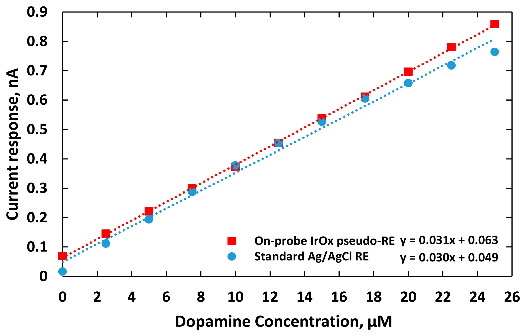
The electric current responses of the sensors were plotted as a function of DA concentration as shown in Figure 10. The DA sensor utilizing IrOx WE and RE had a higher linear regression of 0.9997. It also coupled with less noise although it still had a higher baseline, compared to the one using the external Ag/AgCl RE probe. This is due to the fact that the distance between the IrOx WE and RE was only 500 μm, which was much shorter than the distance between the gold WE and the external Ag/AgCl RE probe that had a fixed distance of 2 cm in our in vitro setup. Consequently, additional interferences from dynamic ion distribution between the electrodes with greater separation in solution added more noises into recorded potentials. The average standard deviation of measurement reflecting the dispersion of the measurement from the average sensor responses at different DA concentrations was 6 pA with the DA sensor integrating the IrOx WE and RE, while for the one using the standard Ag/AgCl RE was around 9 pA. The sensitivities of these two electrodes were 31.7 and 30.3 pA/μM, respectively. The limits of detections (LOD), the lowest quantity of dopamine that can be distinguished [46], were calculated to be 0.01 and 0.5 μM, respectively. Re-calibration after six days manifested the sensor sensitivities with a standard deviation of 27.8 ± 2.9 pA/μM and 28.6 ± 4.0 pA/μM, respectively.
4. Conclusions
The sol-gel fabrication process utilizing a two-step heat treatment was developed to fabricate micro-scale IrOx electrodes on a flexible polymeric substrate. The fabrication processes allowed easy removal of the sacrificial mask layer after patterning while maintaining the film quality. The properties of the IrOx films were similar to the ones fabricated by the one-step heat treatment processes. Sensitivity to pH and longevity of the microelectrodes were studied. Sensor electrode performance did not change significantly over 30 days when they were kept in different environments designed to demonstrate their use in biomedical applications. Electrodes were demonstrated for application in DA concentration recording. The DA sensor with sol-gel IrOx working and pseudo-reference electrodes on the same probe had similar sensitivity but less noise and better limit of detection than the one using a gold working electrode and an external Ag/AgCl reference probe. The flexible sensor with arrayed and integrated IrOx electrodes can be utilized in long-term implants to detect in situ multiple neurotransmitters for diagnosis of neural disorders.
Acknowledgments
The authors would like to express their appreciation to the staff and facilities support at the Shimadzu Institute Nano Technology Research Center, University of Texas at Arlington.
Author Contributions
C.N. and H.C. conceived and designed the experiments; C.N. performed the experiments; X.Y. and S.D. analyzed the data; J.M. developed hardware; C.N., S.R. and J.-C.C. wrote the paper; J.-C.C. was the lead principal investigator.
Conflicts of Interest
The authors declare no conflict of interest.
References
- Hu, Y.; Zhang, Y.; Wilson, G.S. A Needle-Type Enzyme-Based Lactate Sensor for in Vivo Monitoring. Anal. Chim. Acta. 1993, 281, 503–511. [Google Scholar]
- Wang, J.; Liu, J.; Chen, L.; Lu, F. Highly Selective Membrane-Free, Mediator-Free Glucose Biosensor. Anal. Chem. 1994, 66, 3600–3603. [Google Scholar]
- Cao, H.; Li, A.; Nguyen, C.M.; Peng, Y.; Chiao, J.C. An Integrated Flexible Implantable Micro-Probe for Sensing Neurotransmitters. IEEE Sensors J. 2012, 12, 1618–1624. [Google Scholar]
- Tseng, T.T.; Monbouquette, H.G. Implantable Microprobe with Arrayed Microsensors for Combined Amperometric Monitoring of the Neurotransmitters, Glutamate and Dopamine. J. Electroanal. Chem. 2012, 682, 141–146. [Google Scholar]
- Weltin, A.; Enderle, B.; Kieninger, J.; Urban, G.A. A Novel Multiparametric Flexible Microsensor for Metabolic Monitoring in Vivo. Proceedings of the 2013 IEEE Sensors, Baltimore, MD, USA, 3–6 November 2013; pp. 1–3.
- Kulagina, N.V.; Shankar, L.; Michael, A.C. Monitoring Glutamate and Ascorbate in the Extracellular Space of Brain Tissue with Electrochemical Microsensors. Anal. Chem. 1999, 71, 5093–5100. [Google Scholar]
- Huang, W.; Deb, S.; Seo, Y.; Rao, S.; Chiao, M.; Chiao, J.C. A Passive Radio-Frequency pH-Sensing Tag for Wireless Food-Quality Monitoring. IEEE Sensors J. 2012, 12, 487–495. [Google Scholar]
- Nguyen, C.; Huang, W.; Rao, S.; Cao, H.; Tata, U.; Chiao, M.; Chiao, J.C. A Sol-Gel Iridium Oxide Based pH Sensor Array on Flexible Polyimide Substrate. IEEE Sensors J. 2013, 13, 3857–3864. [Google Scholar]
- Hsu, M.; Chen, Y.; Lee, C.; Chiu, H. Gold Nanostructures on Flexible Substrates as Electrochemical Dopamine Sensors. ACS Appl. Mater. Interfaces 2012, 4, 5570–5575. [Google Scholar]
- Ravi Shankaran, D.; Uehara, N.; Kato, T. Sol–Gel Derived Metal Dispersed Ceramic–Graphite Composite Electrode for Amperometric Determination of Dopamine. Anal. Chim. Acta. 2003, 478, 321–327. [Google Scholar]
- Park, I.; Li, Z.; Li, X.; Pisano, A.P.; Williams, R.S. Towards the Silicon Nanowire-Based Sensor for Intracellular Biochemical Detection. Biosens. Bioelectron. 2007, 22, 2065–2070. [Google Scholar]
- Wassum, K.M.; Tolosa, V.M.; Wang, J.; Walker, E.; Monbouquette, H.G.; Maidment, N.T. Silicon Wafer-Based Platinum Microelectrode Array Biosensor for Near Real-Time Measurement of Glutamate in Vivo. Sensors 2008, 8, 5023–5036. [Google Scholar]
- Cellar, N.A.; Kennedy, R.T. A capillary-PDMS Hybrid Chip for Separations-Based Sensing of Neurotransmitters in Vivo. Lab Chip. 2006, 6, 1205–1212. [Google Scholar]
- Shinwari, M.W.; Zhitomirsky, D.; Deen, I.A.; Selvaganapathy, P.; Deen, M.J.; Landheer, D. Microfabricated Reference Electrodes and Their Biosensing Applications. Sensors 2010, 10, 1679–1715. [Google Scholar]
- Gros, P.; Durliat, H.; Comtat, M. Use of Polypyrrole Film Containing Fe(CN)63− as Pseudo-Reference Electrode: Application for Amperometric Biosensors. Electrochim. Acta. 2001, 46, 643–650. [Google Scholar]
- Pedrotti, J.J.; Angnes, L.; Gutz, I.G. Miniaturized Reference Electrodes with Microporous Polymer Junctions. Electroanalysis 1996, 8, 673–675. [Google Scholar]
- Tolosa, V.M.; Wassum, K.M.; Maidment, N.T.; Monbouquette, H.G. Electrochemically Deposited Iridium Oxide Reference Electrode Integrated with an Electroenzymatic Glutamate Sensor on a Multi-Electrode Arraymicroprobe. Biosens. Bioelectron. 2013, 42, 256–260. [Google Scholar]
- Huang, W.; Cao, H.; Deb, S.; Chiao, M.; Chiao, J.C. A Flexible pH Sensor Based on the Iridium Oxide Sensing Film. Sens. Actuators A Phys. 2011, 169, 1–11. [Google Scholar]
- Matsumoto, T.; Ohashi, A.; Ito, N. Development of a Micro-Planar Ag/AgCl Quasi-Reference Electrode with Long-Term Stability for an Amperometric Glucose Sensor. Anal. Chim. Acta. 2002, 462, 253–259. [Google Scholar]
- Park, S.; Jun, S.B.; Park, S.; Kim, H.C.; Kim, S.J. Application of a New Cl-Plasma-Treated Ag/AgCl Reference Electrode to Micromachined Glucose Sensor. IEEE Sensors J. 2003, 3, 267–273. [Google Scholar]
- Moussy, F.; Harrison, D.J. Prevention of the Rapid Degradation of Subcutaneously Implanted Ag/AgCl Reference Electrodes Using Polymer Coatings. Anal. Chem. 1994, 66, 674–679. [Google Scholar]
- Jackson, W.F.; Duling, B.R. Toxic Effects of Silver-Silver Chloride Electrodes on Vascular Smooth Muscle. Circ. Res. 1983, 53, 105–108. [Google Scholar]
- Zhang, Y.; Bindra, D.S.; Barrau, M.; Wilson, G.S. Application of Cell Culture Toxicity Tests to the Development of Implantable Biosensors. Biosens. Bioelectron. 1991, 6, 653–661. [Google Scholar]
- Weiland, J.D.; Anderson, D.J. Chronic Neural Stimulation with Thin-Film, Iridium Oxide Electrodes. IEEE Trans. Biomed. Eng. 2000, 47, 911–918. [Google Scholar]
- Weiland, J.D.; Anderson, D.J.; Humayun, M.S. In Vitro Electrical Properties for Iridium Oxide Versus Titanium Nitride Stimulating Electrodes. IEEE Trans. Biomed. Eng. 2002, 49, 1574–1579. [Google Scholar]
- Slavcheva, E.; Vitushinsky, R.; Mokwa, W.; Schnakenberg, U. Sputtered Iridium Oxide Films as Charge Injection Material for Functional Electrostimulation. J. Electrochem. Soc. 2004, 151, E226–E237. [Google Scholar]
- Lee, I.; Whang, C.; Park, J.; Lee, D.; Seo, W. Biocompatibility and Charge Injection Property of Iridium Film Formed by Ion Beam Assisted Deposition. Biomaterials 2003, 24, 2225–2231. [Google Scholar]
- Grant, S.A.; Bettencourt, K.; Krulevitch, P.; Hamilton, J.; Glass, R. In Vitro and in Vivo Measurements of Fiber Optic and Electrochemical Sensors to Monitor Brain Tissue pH. Sens. Actuators B Chem. 2001, 72, 174–179. [Google Scholar]
- Franklin, R.K.; Johnson, M.D.; Scottt, K.; Shim, J.H.; Nam, H.; Kipke, D.R.; Brown, R.B. Iridium Oxide Reference Electrodes for Neurochemical Sensing with MEMS Microelectrode Arrays. Proceedings of the 2005 IEEE Sensors, Irvine, CA, USA, 30 October–3 November 2005; pp. 1400–1403.
- Inzelt, G. Pseudo-Reference Electrodes. In Handbook of Reference Electrodes; Springer: New York, NY, USA, 2013; pp. 331–332. [Google Scholar]
- Ges, I.A.; Ivanov, B.L.; Werdich, A.A.; Baudenbacher, F.J. Differential pH Measurements of Metabolic Cellular Activity in Nl Culture Volumes using Microfabricated Iridium Oxide Electrodes. Biosen. Bioelectron. 2007, 22, 1303–1310. [Google Scholar]
- Kamegaya, Y.; Sasaki, K.; Oguri, M.; Asaki, T.; Kobayashi, H.; Mitamura, T. Improved Durability of Iridium Oxide Coated Titanium Anode with Interlayers for Oxygen Evolution at High Current Densities. Electrochim. Acta. 1995, 40, 889–895. [Google Scholar]
- Marzouk, S.A. Improved Electrodeposited Iridium Oxide pH Sensor Fabricated on Etched Titanium Substrates. Anal. Chem. 2003, 75, 1258–1266. [Google Scholar]
- Osaka, A.; Takatsuna, T.; Miura, Y. Iridium Oxide Films via Sol-Gel Processing. J. Non-Cryst. Solids 1994, 178, 313–319. [Google Scholar]
- Bard, A.J.; Faulkner, L.R. Electrochemical Methods: Fundamentals and Applications; Wiley: New York, NY, USA, 1980. [Google Scholar]
- Thomas, F.; Henze, G. Introduction to Voltammetric Analysis: Theory and Practice; Csiro Publishing: Victoria, Australia, 2001. [Google Scholar]
- Mohammad-Shiri, H.; Ghaemi, M.; Riahi, S.; Akbari-Sehat, A. Computational and Electrochemical Studies on the Redox Reaction of Dopamine in Aqueous Solution. Int. J. Electrochem. Sci. 2011, 6, 317–336. [Google Scholar]
- Bari, M.R.; Sabzi, R.E. Amperometric Determination of Dopamine on a Glassy Carbon Electrode Chemically Modified with Cobalt Pentacyanonitrosylferrate. Asian J. Chem. 2008, 20, 3357–3363. [Google Scholar]
- Ryan, M.; Lowry, J.; O'Neill, R. Biosensor for Neurotransmitter L-Glutamic Acid Designed for Efficient Use of L-Glutamate Oxidase and Effective Rejection of Interference. Analyst. 1997, 122, 1419–1424. [Google Scholar]
- Cogan, S.F.; Troyk, P.R.; Ehrlich, J.; Plante, T.D.; Detlefsen, D.E. Potential-Biased Asymmetric Waveforms for Charge-Injection with Activated Iridium Oxide (AIROF) Neural Stimulation Electrodes. IEEE Trans. Biomed. Eng. 2006, 53, 327–332. [Google Scholar]
- Klein, J.; Clauson, S.; Cogan, S. Morphology and Charge Capacity of Sputtered Iridium Oxide Films. J. Vac. Sci. Technol. A. 1989, 7, 3043–3047. [Google Scholar]
- Luczak, T.; Beltowska-Brzezinska, M. Gold Electrodes Modified with Gold Nanoparticles and Thio Compounds for Electrochemical Sensing of Dopamine Alone and in Presence of Potential Interferents. A Comparative Study. Microchim. Acta. 2011, 174, 19–30. [Google Scholar]
- Arumugam, P.; Siddiqui, S.; Zeng, H.; Carlisle, J.A. Nanocrystalline Diamond Biosensors. In Biosensors Based on Nanomaterials and Nanodevices; CRC Press: Boca Raton, FL, USA, 2013; pp. 243–245. [Google Scholar]
- Li, G.; Miao, P. Theoretical Background of Electrochemical Analysis. In Electrochemical Analysis of Proteins and Cells; Springer: New York, NY, USA, 2013; pp. 5–18. [Google Scholar]
- Cogan, S.F.; Ehrlich, J.; Plante, T.D.; Smirnov, A.; Shire, D.B.; Gingerich, M.; Rizzo, J.F. Sputtered Iridium Oxide Films for Neural Stimulation Electrodes. J. Biomed. Mater. Res. Part B Appl. Biomater 2009, 89, 353–361. [Google Scholar]
- Shrivastava, A.; Gupta, V.B. Methods for the Determination of Limit of Detection and Limit of Quantitation of the Analytical Methods. Chron. Young Sci. 2011, 2, 21–25. [Google Scholar]


© 2015 by the authors; licensee MDPI, Basel, Switzerland. This article is an open access article distributed under the terms and conditions of the Creative Commons Attribution license ( http://creativecommons.org/licenses/by/4.0/).
Share and Cite
Nguyen, C.M.; Rao, S.; Yang, X.; Dubey, S.; Mays, J.; Cao, H.; Chiao, J.-C. Sol-Gel Deposition of Iridium Oxide for Biomedical Micro-Devices. Sensors 2015, 15, 4212-4228. https://doi.org/10.3390/s150204212
Nguyen CM, Rao S, Yang X, Dubey S, Mays J, Cao H, Chiao J-C. Sol-Gel Deposition of Iridium Oxide for Biomedical Micro-Devices. Sensors. 2015; 15(2):4212-4228. https://doi.org/10.3390/s150204212
Chicago/Turabian StyleNguyen, Cuong M., Smitha Rao, Xuesong Yang, Souvik Dubey, Jeffrey Mays, Hung Cao, and Jung-Chih Chiao. 2015. "Sol-Gel Deposition of Iridium Oxide for Biomedical Micro-Devices" Sensors 15, no. 2: 4212-4228. https://doi.org/10.3390/s150204212