A Solid State Nanopore Device for Investigating the Magnetic Properties of Magnetic Nanoparticles

Abstract
: In this study, we explored magnetic nanoparticles translocating through a nanopore in the presence of an inhomogeneous magnetic field. By detecting the ionic current blockade signals with a silicon nitride nanopore, we found that the translocation velocity that is driven by magnetic and hydrodynamic forces on a single magnetic nanoparticle can be accurately determined and is linearly proportional to the magnetization of the magnetic nanoparticle. Thus, we obtained the magneto-susceptibility of an individual nanoparticle and the average susceptibility over one hundred particles within a few minutes.1. Introduction
The most important issue for magnetic materials is an understanding of the magnetic and physical properties of a nanometer-sized particle because the use of magnetic nanoparticles (MNPs) in many applications depends predominantly on their inherent magnetic properties. In the case of biomedical applications, the forces that influence the translational, rotational, and vibrational motion of a MNP- tagged biomolecule are the magnetic force due to the magnetization of an individual MNP and the external magnetic field under a given condition [1–3]. Popular magnetic biosensing platforms such as giant magneto-resistance (GMR) sensors, Hall sensors, and magneto-optical sensors that are used to quantitatively analyze the existence of target molecules are based on the detection of a stray field from a single MNP [4–7]. Furthermore, structural assemblies of MNPs form various recording media and permanent magnets [8].
Recently, there have been many attempts to quantitatively analyze a biomolecule by magnetically manipulating the motion of magnetic beads in a microfluidic system because magnetic interactions are generally not affected by changes in the surface charges, pH, or ionic concentration of the surrounding medium, contrary to electrical-driven manipulation [9].
To precisely manipulate the motion, we should know the characteristics of the MNP, e.g., the size, charge state, and magnetism. There are well-established techniques for investigating the physical and electrical properties of a nanoparticle. For instance, the size and surface charge state of a nanoparticle can be routinely characterized by dynamic light scattering (DLS) and zeta-potentiometry, respectively. These methods can provide information on the distributions and the average values of the size and charge number of each particle. Magnetic characteristics have been usually determined by a superconducting quantum interference device (SQUID) and by a vibrating sample magnetometer (VSM). Unlike DLS and zeta-potentiometry, these techniques, although they have excellent sensitivities, are limited to the average properties of a large number of MNPs. To the best of our knowledge, the resultant data from these techniques do not provide sufficient information on the magnetism of a MNP, which may be considered as a critical bottleneck in facilitating the use of MNPs in various industrial applications. Therefore, the need to characterize a single MNP has been increasingly recognized.
In this work, we investigate the motion of MNPs, 30 nm in diameter, that are driven by both magnetic and electric forces in a nanopore membrane. In this investigation, we measured the velocity of the MNPs passing through the nanopore using an ionic current blockade. We found that the magnetic force enables the MNPs to move more rapidly and that the velocity is linearly proportional to the magnetization of a MNP. Thus, we were able to measure the magnetization of a single colloidal MNP and to acquire hundreds of data points on the magnetization within a few minutes.
2. Methods
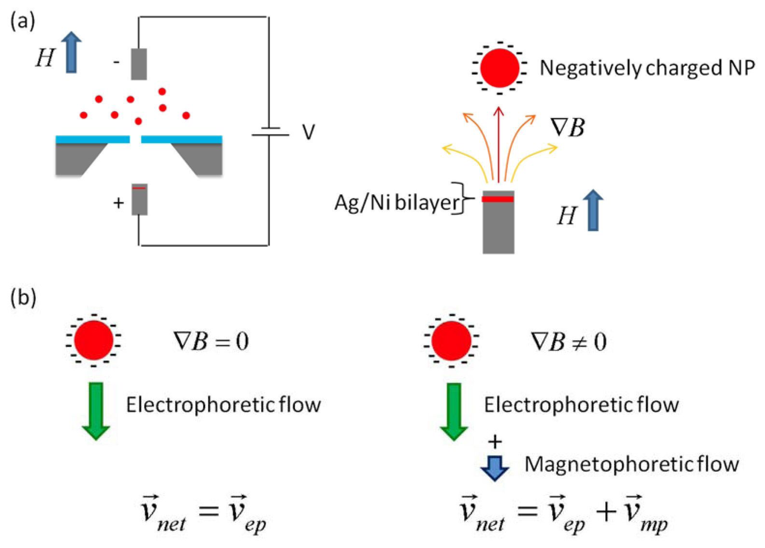
A nanopore chip, which has a single nanometer-sized hole in a free-standing ultrathin membrane between two miniaturized fluidic chambers (“cis” and “trans”), is hydrated by conducting a fluid through it. An electric potential is applied across the chip; an electric current is used because the conduction of ions through the nanopore can be observed. When MNPs with negative charges are immersed in the cis chamber, they are captured and linearly threaded through the nanopore from the cis to trans chamber, as shown in Figure 1, and the current between the two electrodes is momentarily interrupted, which is the so-called “ionic current blockade”. The magnitude (ΔIc) and dwell-time (Δt) of the current blockade are governed by the size of the particle under given conditions [10]:
Here, Ic is the measured ionic current upon the application of a membrane potential (V), and Q is the charge on a particle; lc, dc, dd, and ds are the channel length, channel width, Debye length and particle diameter, respectively. For the simplicity, the counter flow effect induced by the counter-ion buildup around the charged nanoparticle was not included. The factor 0.8dc corrects for the so-called “end effect”, which becomes significant when the pore diameter is comparable to the pore length [8]. S(dc, ds) is a correction factor that depends on the relative values of dc and ds, and is very close to 1 for most cases [11]. From the measured current (ΔIc) and dwell-time (Δt), we determine not only the diameter of a single particle but also the translocation velocity, which is mainly due to electrophoresis in the nanopore.
By applying an inhomogeneous magnetic field parallel to the electric field, the MNPs can be pulled in the field direction due to a magnetophoretic flow, which can be simply described by the relation between the magnetic drag force (Fmag) and the opposing hydrodynamic drag force (Fh) [12,13]:
Here, η is the viscosity of the surrounding medium and vmp is the velocity of a particle due to the magnetophoretic flow. The resultant velocity is linearly proportional to the magnetization of a single MNP. Therefore, magnetization can be obtained by measuring the net velocity (vnet), which is composed of vmp and vep.
The basic principle of work is based on the following two factors: (i) electrophoresis: the pull of the MNP into the nanopore with vep; (ii) magnetophoresis: changing the net velocity (vnet = vep + vmp). The velocity obtained is converted into the magnetization per particle using Equation (6).
3. Experiments
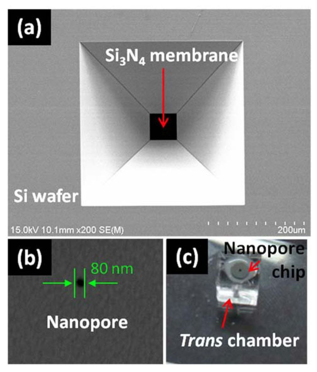
The detector that was used in this study was a solid-state nanopore, which was fabricated in a freestanding silicon nitride (Si3N4) membrane using conventional MEMS technology (see Figure 2) [14,15]. The Ic, and dc were kept at 30 nm and 80 nm, respectively. The cis and trans chamber set was fabricated with PDMS (Sylgard 184, Dow Corning, Inc., Midland, MI, USA) and was 1 mm in diameter. A 0.5 M KCl solution without buffer was used as a conducting solution and was prepared using deionized water and KCl powder purchased from Sigma-Aldrich, Co. (St. Louis, MO, USA), followed by filtration through a 0.2 syringe filter (Whatman, Ltd., Piscataway, NJ, USA) prior to use. The MNPs that were used in this experiment were obtained from Nanobrick, Inc. (Suwon, Korea) and from Micromod, GmbH (Rostock, Germany) and were negatively charged and tetrabutylammonium hydroxide-stabilized.
The Si3N4 nanopore was clamped between the two half chambers, sealed with epoxy, and then placed in the center of a vertical Helmholtz coil in a Faraday cage on a vibration-isolated optical bench. The ionic current was measured in the voltage-clamp mode with an integrated data acquisition system (Axopatch 200B and Digidata 1440A, Molecular Devices, LLC, Sunnyvale, CA, USA). An inhomogeneous magnetic field was generated around the nanopore by magnetic induction from a Ag/Ni/AgCl electrode coupled with the magnetic field in the Helmholtz coil. The magnetic field was measured using a commercial magnetic sensor (Model 410 Gaussmeter, Lake Shore Cryonics, Inc., Westerville, OH, USA) to obtain a spatial distribution of the magnetic field. First, the magnetic sensor was located at the fixed position where the nanopore would be located in the translocation velocity measurements. Then, the Ag/Ni/AgCl electrode was moved precisely from one location to another by a micromanipulator to measure a distance (between the nanopore and the Ni-coated electrode) dependent magnetic fields. Thus, the magnetic field profile near the nanopore was obtained at a given (induced) magnetic field, and then the gradient of the magnetic field at the nanopore was extracted from the measured magnetic field profile. With the information obtained above, we could magnified measure translocation velocity under various magnetic fields, and extract the magnetization-magnetic field (M-B) curve from Equation (6). The Ag/Ni/AgCl electrode was fabricated by e-beam evaporation of Ni and Ag on a AgCl pellet.
4. Results
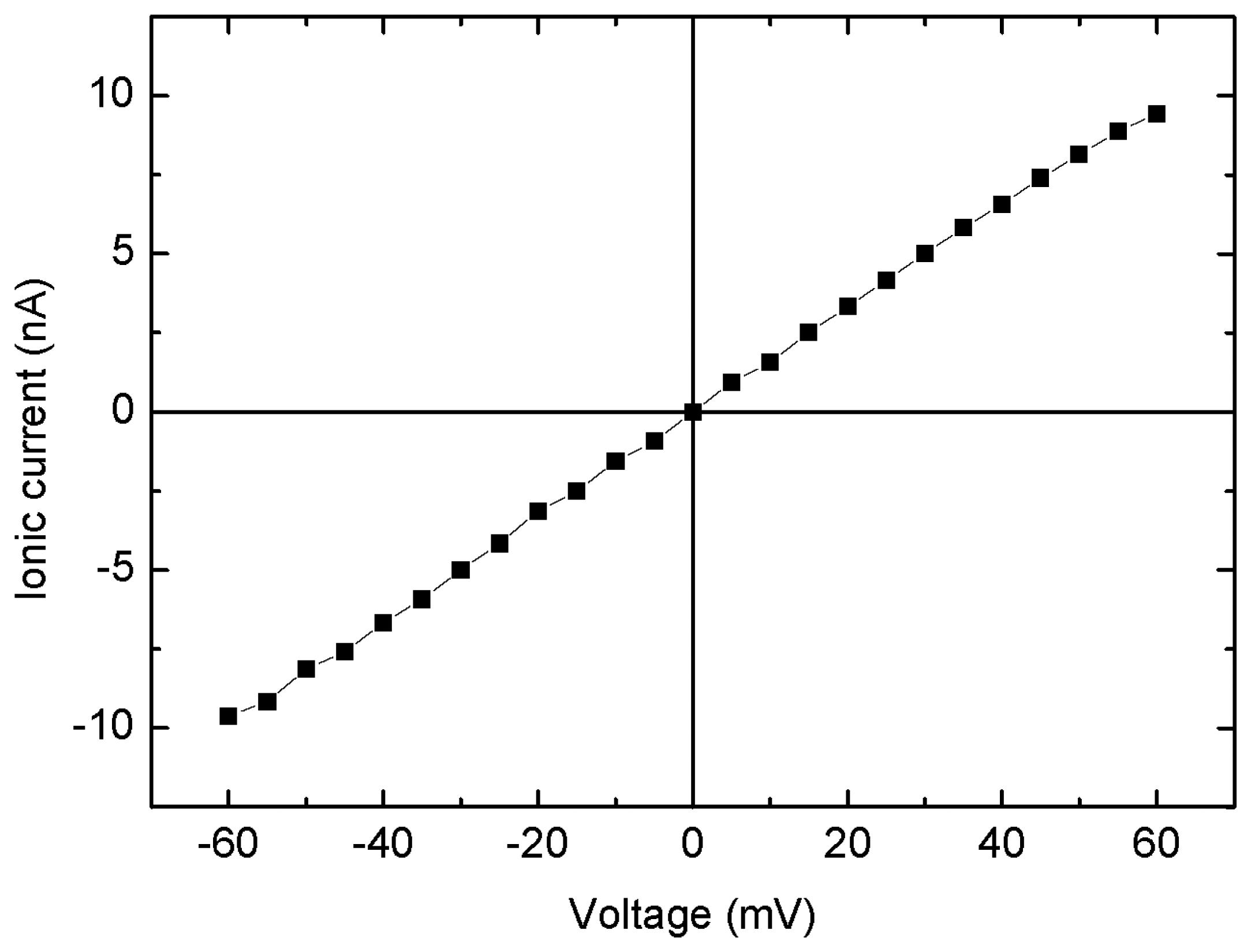
The Ic-V characteristics of the nanopore device with an 80 nm pore diameter and a 30 nm thick silicon nitride membrane are shown in Figure 3. The voltage was swept from −0.1 V to +0.1 V. The experimental and theoretical [16] conductance values were found to be 126 and 285 nS, respectively. Thus, the theoretical value (285 nS) is twice as large as the experimental value (126 nS). This inconsistency may be due to the underestimated dimension and the non-ideal shape of the nanopore. The calculation of the conductance used the assumption that the nanopore is cylindrical and has a very smooth wall. However, the actual shape is not cylindrical, but rather is close to hourglass-like [17,18]. Therefore, the effective length is shorter and the radius is smaller than the actual physical diameter which could be determined by FE-SEM. Furthermore, the roughness of the nanopore wall effectively reduces the diameter.
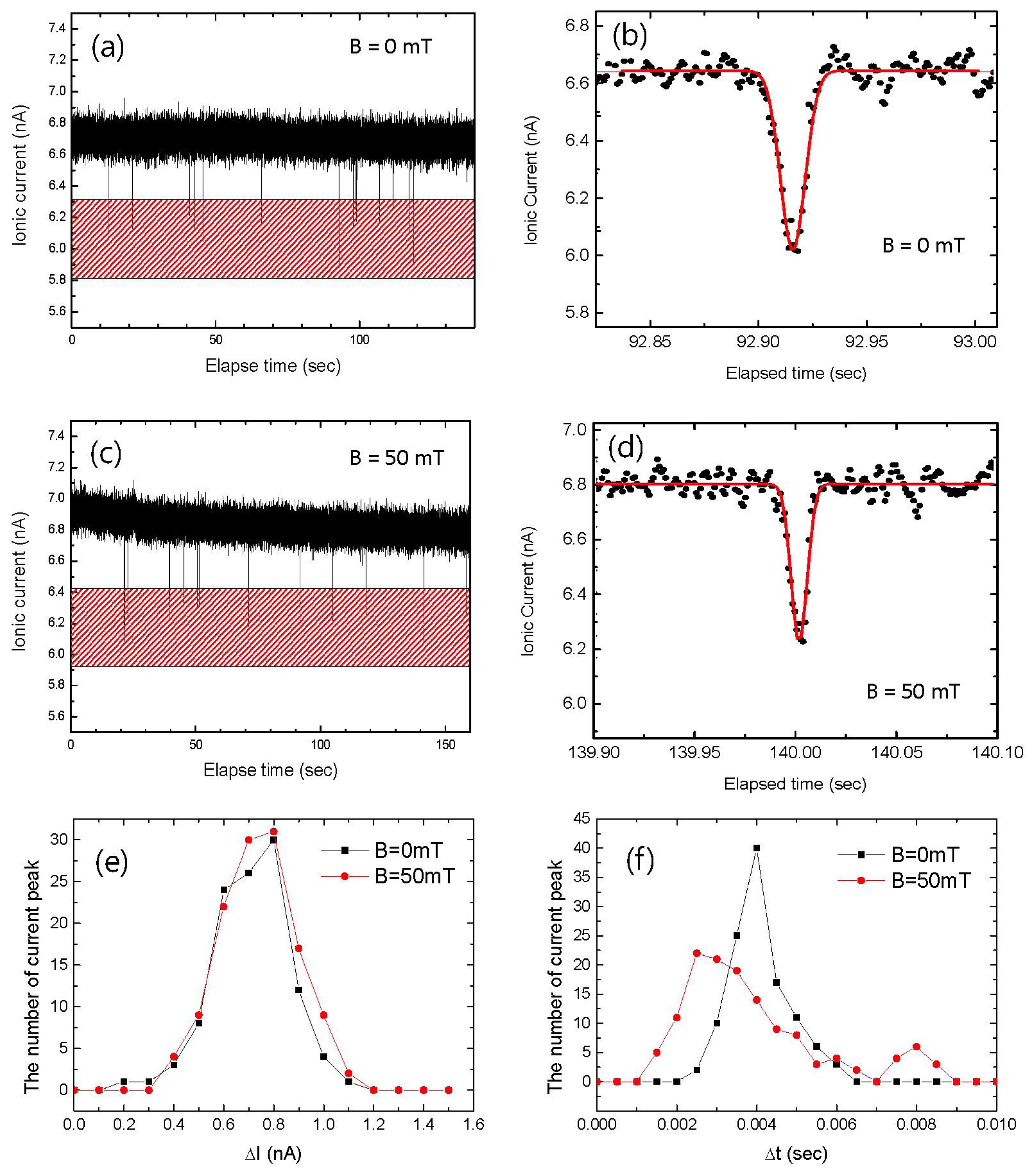
Figure 4 shows the time-dependent ionic current (Ic vs. t recording) for 5 min. Hundreds of current blockade events could be observed due to MNP translocation for both B = 0 in Figure 4(a,b) and B ≠ 0 in Figure 4(c,d). The current blockades that are shown in Figure 4(b,d) have a slightly asymmetric triangular shape, consistent with those of spherical particles in previous works [19]. To obtain ΔIc and Δt, the current blockades were simply fitted with a Gaussian curve rather than with multiple peaks because Gaussian fitting is more intuitive for the understanding of the motion of a single sphere. By fitting a hundred current blockade events, histograms of ΔIc and Δt were obtained as shown in Figure 4(e,f), respectively. It should be noted that the average value of ΔIc for B = 0 mT was the same as that for B = 50 mT, whereas Δt for B = 50 mT was shortened by approximately 28%. The histograms reflect the fact that ΔIc is only dominantly governed by the size of a single particle from Equation (1), while Δt stems from the velocity that is driven not only by the electrophoresis from Equation (3) but also by the magnetophoresis from Equation (6). Therefore, the size and magnetization of a single MNP could be determined from the ΔIc and Δt histograms, respectively.
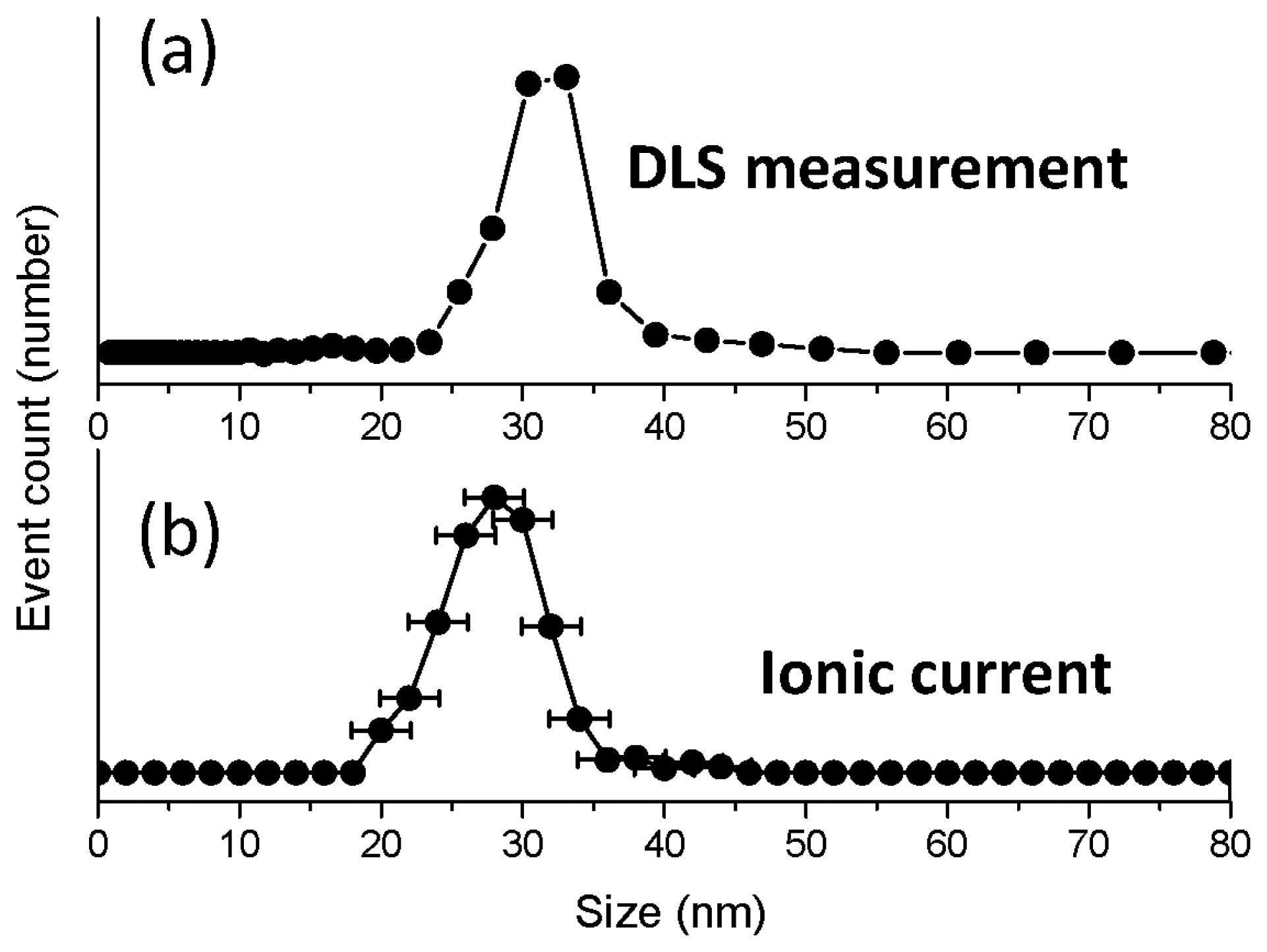
We compared the size distribution from ΔIc with the one taken from dynamic light scattering (DLS) as shown in Figure 5. The distribution from the DLS experiment, which is shown in Figure 5(a), revealed that the most frequent size and the average value are 33 nm and 31.3 nm, respectively, which are very close to the anticipated numbers. The distribution from ΔIc, which is shown in Figure 5(b), was in a good agreement with that from DLS. The error likely arises from the background current noise.
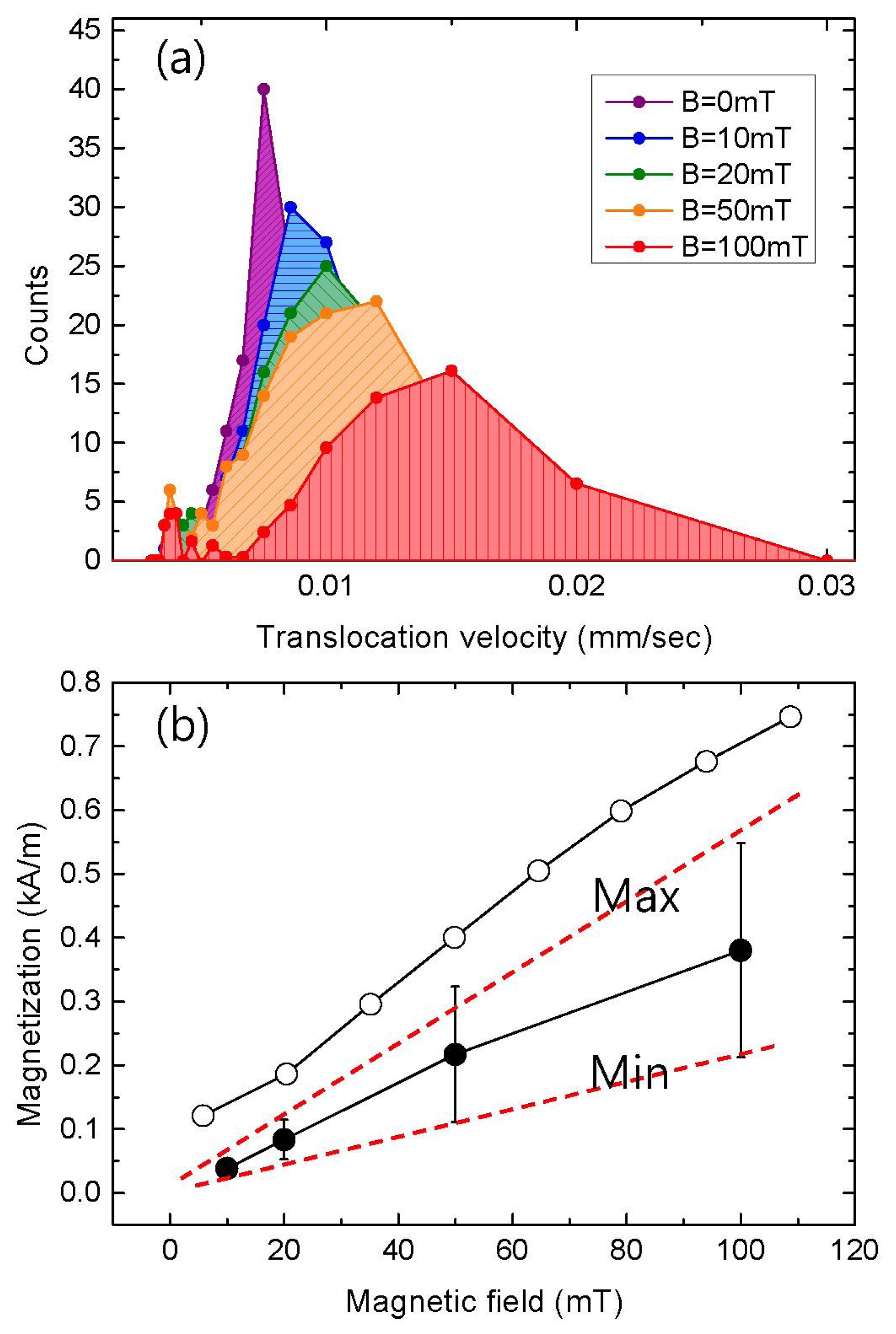
To explicitly verify the effect of the magnetic force on the velocity, the translocation velocity was measured as a function of the external magnetic field, as shown in Figure 6(a). It can be seen that the velocity increased with increasing external magnetic field. This tendency indicates that the change in the velocity is mainly driven by the magnetic force between the external field and the MNPs. It should be noted that the histograms broadened with an increase in the magnetic field. The dependence of this broadening on the external magnetic field could be explained by the existence of slightly different magnetizations among the MNPs, which would lead to a variation in the slope of the M-B curve (which is proportional to the magnetic susceptibility). This variation in the susceptibility would enable the distribution of the velocity to broaden with an increase in the external field. Figure 6(b) shows a comparison of the M-B curves from the velocity measurements with that from VSM measurements. The velocity was converted to the magnetization per particle using Equation (6) in the Section 2. For high magnetic field regime at B = 100 mT, the gradient of the magnetic field on the order of 100 T/m was obtained from the field vs. distance measurement as described in the Section 3. The susceptibility from the ionic current was linearly proportional to the magnetic field in the range of B < 100 mT, and was approximately half the value of the VSM result of 1.6. The discrepancy in the absolute value of the susceptibility might be due to errors in the effective parameter estimations including the “end effect”, but is still under investigation.
5. Conclusions
We have investigated the properties of magnetic nanoparticles translocating through a solid-state nanopore in the presence of an inhomogeneous magnetic field. By measuring and analyzing the ionic current blockade, the translocation velocity of a nanoparticle passing through a nanometer-scale channel was found to be linearly proportional to the magnetization of the single magnetic nanoparticle. We have also shown the possibility of using this method to analyze the magnetic properties of hundreds of individual nanoparticles within a few minutes. We expect that this method will find a number of interesting applications, not only for characterizing the magnetic properties of inorganic nanoparticles but also for manipulating and analyzing organic and biological molecules that have been hybridized with magnetic nanoparticles.
Acknowledgments
This work was supported by the Industrial Strategic Technology Development Program, (10037410-2011-02, Development of Next Generation DNA Sequencer), funded by the Ministry of Knowledge Economy (MKE, Korea). This research was also supported by the grant (2012-P3-14) from the Advanced Institutes of Convergence Technology (AICT) and the Ministry of Education, Science and Technology of Korea as Global Frontier Project (CISS-2012366054204).
Conflict of Interest: The authors declare no conflict of interest.
References
- Koh, I.; Josephson, L. Magnetic nanoparticle sensors. Sensors 2009, 9, 8130–8145. [Google Scholar]
- Haun, J.B.; Yoon, T.-J.; Lee, H.; Weissleder, R. Magnetic nanoparticle biosensors. Wiley Interdiscip. Rev. Nanomed. Nanobiotechnol. 2010, 2, 291–304. [Google Scholar]
- Biswal, S.L.; Gast, A.P. Micromixing with linked chains of paramagnetic particles. Anal. Chem. 2004, 76, 6448–6455. [Google Scholar]
- Sandhu, A.; Kumagai, Y.; Lapicki, A.; Sakamoto, S.; Abe, M.; Handa, H. High efficiency Hall effect micro-biosensor platform for detection of magnetically labeled biomolecules. Biosens. Bioelectron. 2007, 22, 2115–2120. [Google Scholar]
- Park, S.Y.; Handa, H.; Sandhu, A. Magneto-optical biosensing platform based on light scattering from self-assembled chains of functionalized rotating magnetic beads. Nano Lett. 2010, 10, 446–451. [Google Scholar]
- Baselt, D.R.; Lee, G.U.; Natesan, M.; Metzger, S.W.; Sheehan, P.E.; Colton, R.J. A biosensor based on magnetoresistance technology. Biosens. Bioelectron. 1998, 13, 731–739. [Google Scholar]
- Park, S.Y.; Handa, H.; Sandhu, A. Determination of inter-molecular forces by magneto-optical transmittance of molecule-covered superparamagnetic particles in solution. IEEE Trans. Magn. 2010, 46, 1409–1411. [Google Scholar]
- Wang, J.P. FePt Magnetic nanoparticles and their assembly for future magnetic media. Proc. IEEE 2008, 96, 1847–1863. [Google Scholar]
- Choi, J.W.; Oh, K.W.; Thomas, J.H.; Heineman, W.R.; Halsall, H.B.; Nevin, J.H.; Helmicki, A.J.; Henderson, H.T.; et al. An integrated microfluidic biochemical detection system for protein analysis with magnetic bead-based sampling capabilities. Lab Chip 2002, 2, 27–30. [Google Scholar]
- Overbeek, J.T.G.; Wiersema, P.H. Interpretation of Electrophoretic Mobilities. In Electrophoresis: Theory, Methods and Applications; Bier, M., Ed.; Academic Press: New York, NY, USA, 1967; Volume 2, pp. 1–52. [Google Scholar]
- Deblois, R.W.; Bean, C.P. Counting and Sizing of Submicron Particles by Resistive Pulse Techniques. Rev. Sci. Instrum. 1970, 41, 909–916. [Google Scholar]
- Pamme, N. Continuous flow separations in microfluidic devices. Lab Chip 2007, 7, 1644–1659. [Google Scholar]
- Häfeli, U.O.; Lobedann, M.A.; Streingroewer, J.; Moore, L.R.; Riffle, J. Optical method for measurement of magnetophoretic mobility of individual magnetic microspheres in defined magnetic field. J. Magn. Magn. Mater. 2005, 293, 224–239. [Google Scholar]
- Storm, A.J.; Chen, J.H.; Ling, X.S.; Zandbergen, H.W.; Dekker, C. Fabrication of solid-state nanopores with single-nanometre precision. Nat. Mater. 2003, 2, 537–540. [Google Scholar]
- Krapf, D.; Wu, M.Y.; Smeets, R.M.M.; Zandbergen, H.W.; Dekker, C.; Lemay, S.G. Fabrication and characterization of nanopore-based electrodes with radii down to 2 nm. Nano Lett. 2006, 6, 105–109. [Google Scholar]
- Kowalczyk, S.W.; Grosberg, A.Y.; Rabin, Y.; Dekker, C. Modeling the conductance and DNA blockade of solid-state nanopores. Nanotechnology 2011, 22, 315101. [Google Scholar]
- Wu, M.Y.; Smeets, R.M.M.; Zandbergen, M.; Ziese, U.; Krapf, D.; Batson, P.E.; Dekker, N.H.; Dekker, C.; Zandbergen, H.W. Control of shape and material composition of solid-state nanopores. Nano Lett. 2009, 9, 479–484. [Google Scholar]
- Haynes, W.M., Ed.; CRC Handbook of Chemistry and Physics, 91st ed.; CRC Press: Boca Raton, FL, USA, 2010.
- Ito, T.; Sun, L.; Crooks, R.M. Simultaneous determination of the size and surface charge of individual nanoparticles using a carbon nanotube-based coulter counter. Anal. Chem. 2003, 75, 2399–2406. [Google Scholar]


© 2013 by the authors; licensee MDPI, Basel, Switzerland. This article is an open access article distributed under the terms and conditions of the Creative Commons Attribution license (http://creativecommons.org/licenses/by/3.0/).
Share and Cite
Park, S.; Lim, J.; Pak, Y.E.; Moon, S.; Song, Y.-K. A Solid State Nanopore Device for Investigating the Magnetic Properties of Magnetic Nanoparticles. Sensors 2013, 13, 6900-6909. https://doi.org/10.3390/s130606900
Park S, Lim J, Pak YE, Moon S, Song Y-K. A Solid State Nanopore Device for Investigating the Magnetic Properties of Magnetic Nanoparticles. Sensors. 2013; 13(6):6900-6909. https://doi.org/10.3390/s130606900
Chicago/Turabian StylePark, SangYoon, Jaekwan Lim, Y. Eugene Pak, Seunghyun Moon, and Yoon-Kyu Song. 2013. "A Solid State Nanopore Device for Investigating the Magnetic Properties of Magnetic Nanoparticles" Sensors 13, no. 6: 6900-6909. https://doi.org/10.3390/s130606900