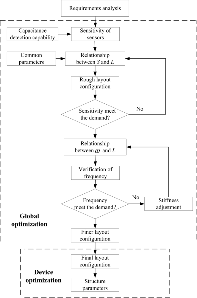
After choosing a feasible topology for each inertial sensor, we must determine the dimensions for each sensor. However, the MIMU consists of six separated inertial sensors, which means the usual device optimization approaches, such as a genetic algorithm (GA) [
36] or simulated annealing algorithm (SAA) [
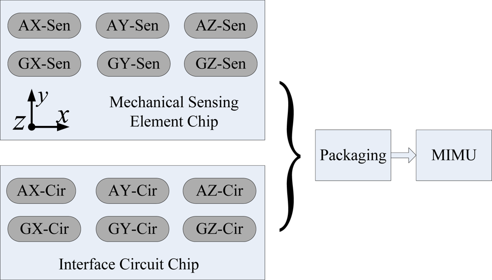
37], are not suitable to be applied directly to MIMU design. Therefore, area occupations for each sensor should be determined first before the detailed design for the single sensor. In this paper, we propose an area optimization approach to establish the layout configuration for MIMU.
3.2. Sensitivity versus Layout Area
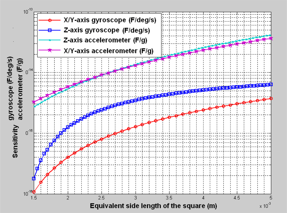
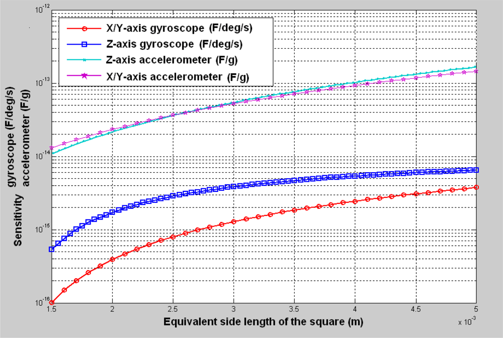
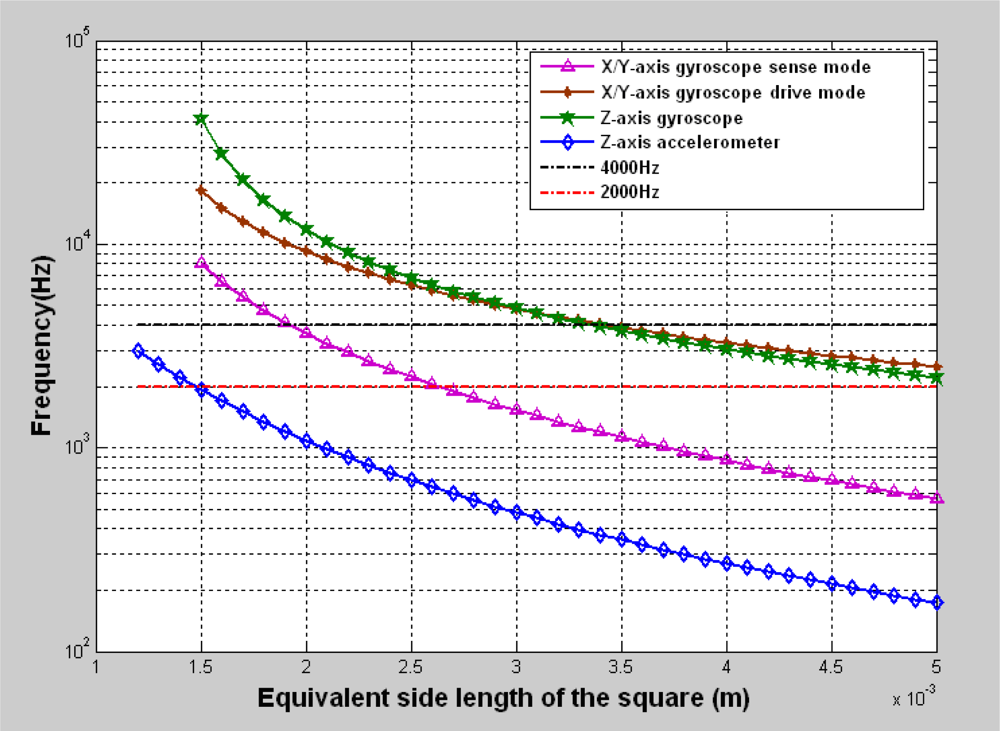
Because there is an area limitation to design inertial sensors using the bulk micromachining process, it is useful to find the relationship between the performance and the area. We deduce a simplified relationship between the sensitivity and the layout area with some assumptions and some available dimensions.
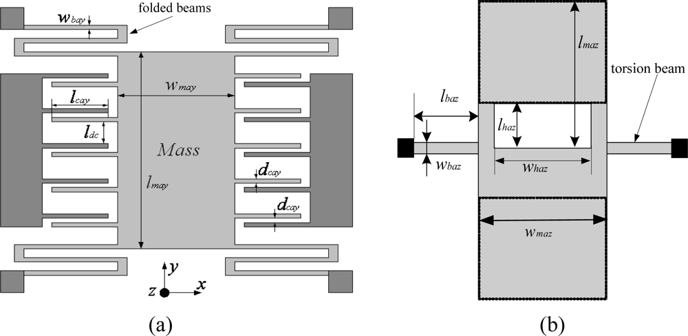
The sensitivity and resonant frequency of the X/Y-axis accelerometer can be described as the following:
where
lmay,
wmay,
lbay,
wbay,
lcay,
dcay are shown in
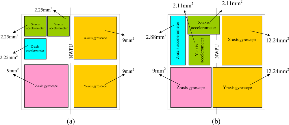
Figure 3 (a);
lmay and
wmay are the length and width of the inertial mass of the X/Y-axis accelerometer;
lbay and
wbay are the length and width of the bending beams;
lcay is the overlap of the comb fingers;
dcay is the gap between capacitor plate;
n is the number of comb fingers;
h is the thickness of the structure;
ωay is the natural resonant frequency of the X/Y-axis accelerometer;
ε0 is the dielectric constant of the air;
E is Young’s modulus of silicon; and
ρ is density of silicon.
It can be seen from
Equation (1) that the sensitivity of the X/Y-axis accelerometer is proportional to the number of comb fingers, which is evident in some parameters, such as the overlap, thickness and gap, which are shown in
Table 1. As for the biased comb capacitors,
ldc is usually set to be much bigger than the gap
dcay; here,
ldc =
dcay. To ensure the inertial mass of the accelerometer is large enough, we assumed that the area occupied by the biased comb capacitors is about a quarter of the total area of the accelerometer. Therefore, we can assume that the sensitivity of the X/Y-axis accelerometer is only related to its area. To further simplify the relationship, we assumed that the area of the X/Y-axis accelerometer is represented by an equivalent square with an equivalent side length. Consequently, the equivalent side length for X/Y-axis accelerometer is approximated as
when the area occupied by the fingers is ignored.
As for the Z-axis accelerometer, the sensitivity and resonant frequency formulas are:
where
lbaz,
wbaz,
lmaz ,
wmaz,
lhaz ,
whaz are shown in
Figure 3 (b);
lbaz and
wbaz are the length and width of the bending beams, respectively;
lmaz and
wmaz are the length and width of the inertial mass, respectively;
lhaz and
whaz are the length and width of the hole, respectively;
d0 is the gap between structure and the substrate;
ωza is the natural resonant frequency of the Z-axis accelerometer;
G is torsion modulus; and
β is torsion coefficient.
It can be seen from
Equation (3) that the sensitivity of the Z-axis accelerometer is related to the area of the inertial mass (
lmaz ×
wmaz) and the ratio
lhaz/
lmaz. The sensitivity reaches its maximum when the ratio is about 0.7. Furthermore, in order to ensure a large stiffness in the Z-axis direction, we set
whaz = 0.5 ×
wmaz. Therefore, we can obtain an equivalent side length for the Z-axis accelerometer,
, with a similar assumption.
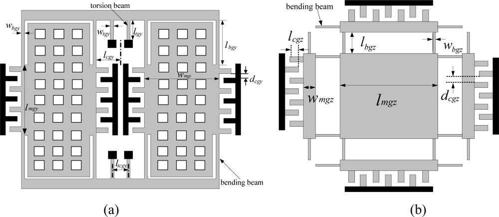
For the X/Y-axis gyroscope, the sensitivity and resonant frequency formulas are:
where
lmgy,
wmgy,
lbgy,
wbgy,
ltgy,
wtgy,
lcgy are shown in
Figure 4 (a);
ltgy and
wtgy are the length and width of the torsion beams, respectively;
dcgy is the width of the comb fingers;
d0 is the gap between structure and substrate;
h is thickness of the structure;
ωdgy is the natural resonant frequency of drive mode;
ωsgy is natural resonant frequency of sense mode;
ρ is the density of the silicon;
μ* is the dynamic viscosity of the air;
Vp is DC voltage; and
va is the AC voltage.
It can be seen from
Equation (5) that the sensitivity of the X/Y-axis gyroscope is related to its area of inertial mass because the beam dimensions of the beams were given a group of initial values. An equivalent side length for the X/Y-axis gyroscope can be given as
.
As for the Z-axis gyroscope, the sensitivity and resonant frequency formulas are :
where
lmgz,
wmgz,
lbgz,
wbgz are shown in
Figure 4 (b);
dcgz is the width of the comb fingers;
h is thickness of the structure;
ωgz is the natural resonant frequency of the Z-axis gyroscope; and
Vp is DC voltage;
va is AC voltage.
It can be seen from
Equation (8) that the sensitivity of the Z-axis gyroscope is related to its area of inertial mass because the beam dimensions were given a group of initial values. An equivalent side length for Z-axis gyroscope can be given as
Lgz =
lmgz + 2 × (
lbgz − 50).
All the formulas for the equivalent side length are listed in
Table 2. Based on these formulas, the sensitivity is dependent on just one variable related to its area. We can use this relationship in our global optimization to determine the layout configuration for these six sensors.


