In Situ Electrochemical SFG/DFG Study of CN− and Nitrile Adsorption at Au from 1-Butyl-1-methyl-pyrrolidinium Bis(trifluoromethylsulfonyl) Amide Ionic Liquid ([BMP][TFSA]) Containing 4-{2-[1-(2-Cyanoethyl)-1,2,3,4-tetrahydroquinolin-6-yl]diazenyl} Benzonitrile (CTDB) and K[Au(CN)2]

 ,
,
Abstract
:1. Introduction
2. Results and Discussion
2.1. Cyclic Voltammetry

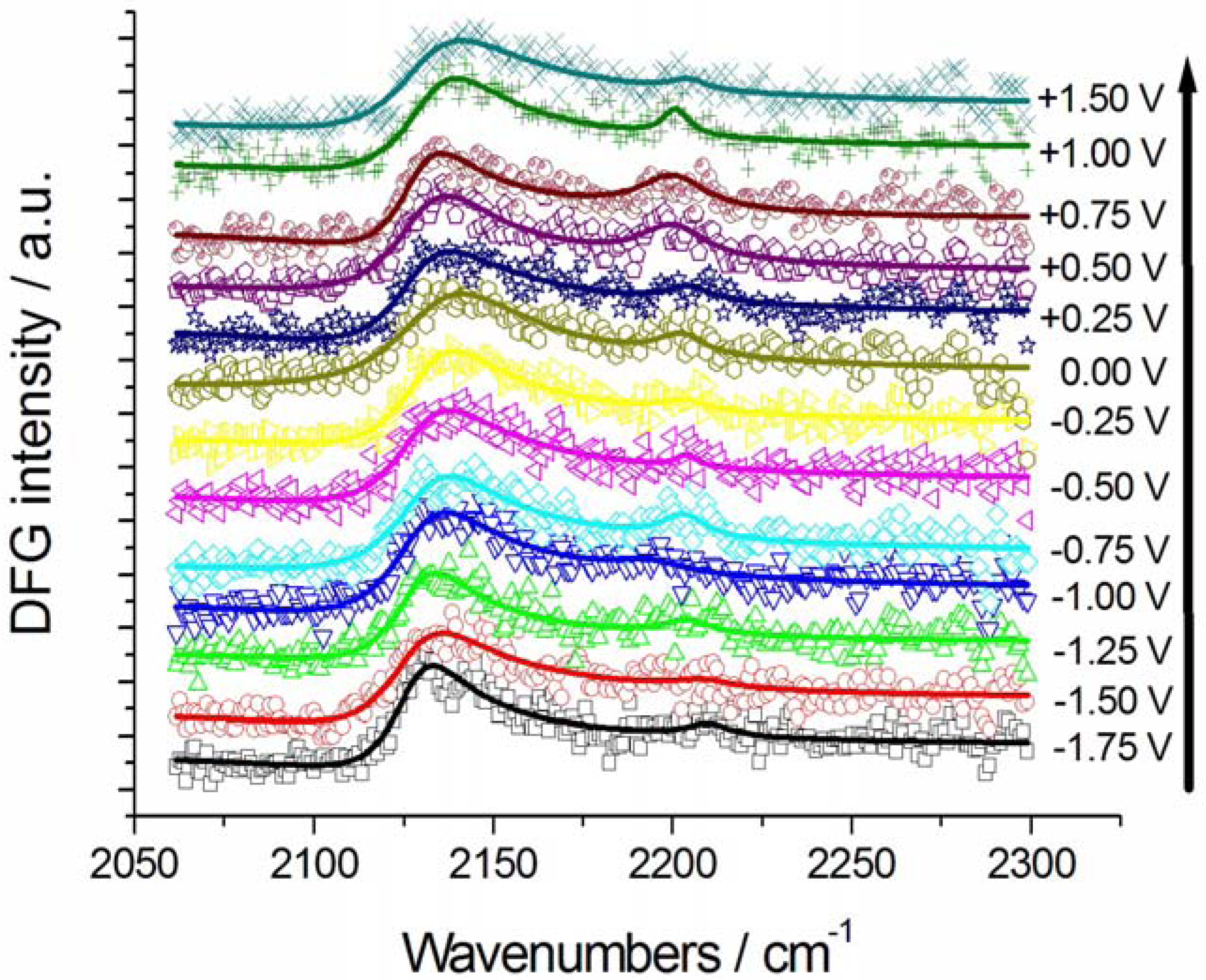
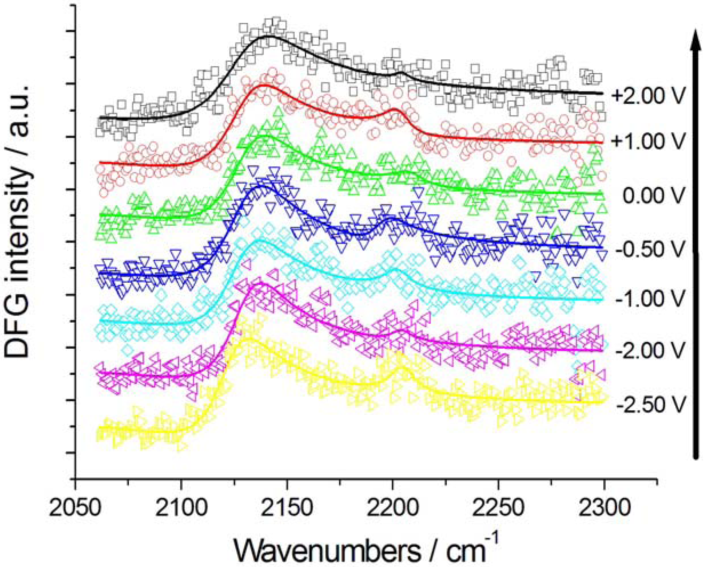
2.2. In Situ Sum- and Difference-Frequency Generation Spectroscopy (SFG/DFG)
 (for details, see the Appendix), as a result of interference between the resonant and non-resonant contributions. Furthermore, DFG spectroscopy with Au electrodes exhibits a better signal-to-noise ratio owing to the absence of a non-resonant background.
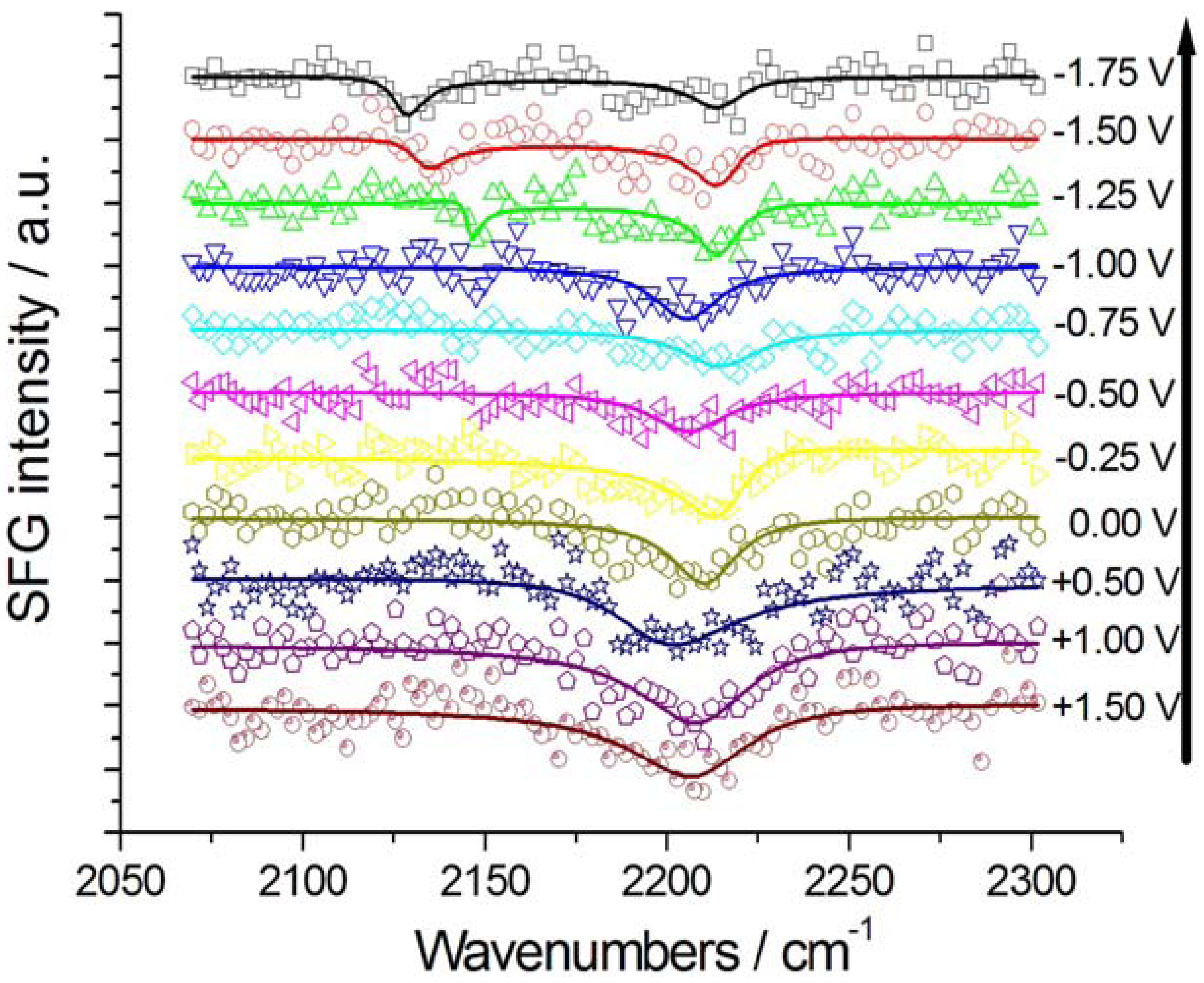
2.2.1. Adsorption and Cathodic Reaction of CTDB in [BMP][TFSA]


2.2.2. Electrodeposition of Au from a [BMP][TFSA]-based solution containing CTDB and K[Au(CN)2]
3. Experimental
3.1. Single-Resonance Model for SFG/DFG


 , by simple algebra it can be shown that:
 ,
,  and
and  . The form of Equation (3) - with ωo, α, β and δ as fit parameters, ensures minimal parameter correlation for the NLLS fitting procedure [9]. Furthermore, Equation (3) allows a straightforward analytical interpretation of the parameter set
  : (i) α is the background far from the resonance; (ii) ωo is the peak position in case of a pure Lorentzian lineshape; (iii)
  is a Lorentzian lineshape; (iv)
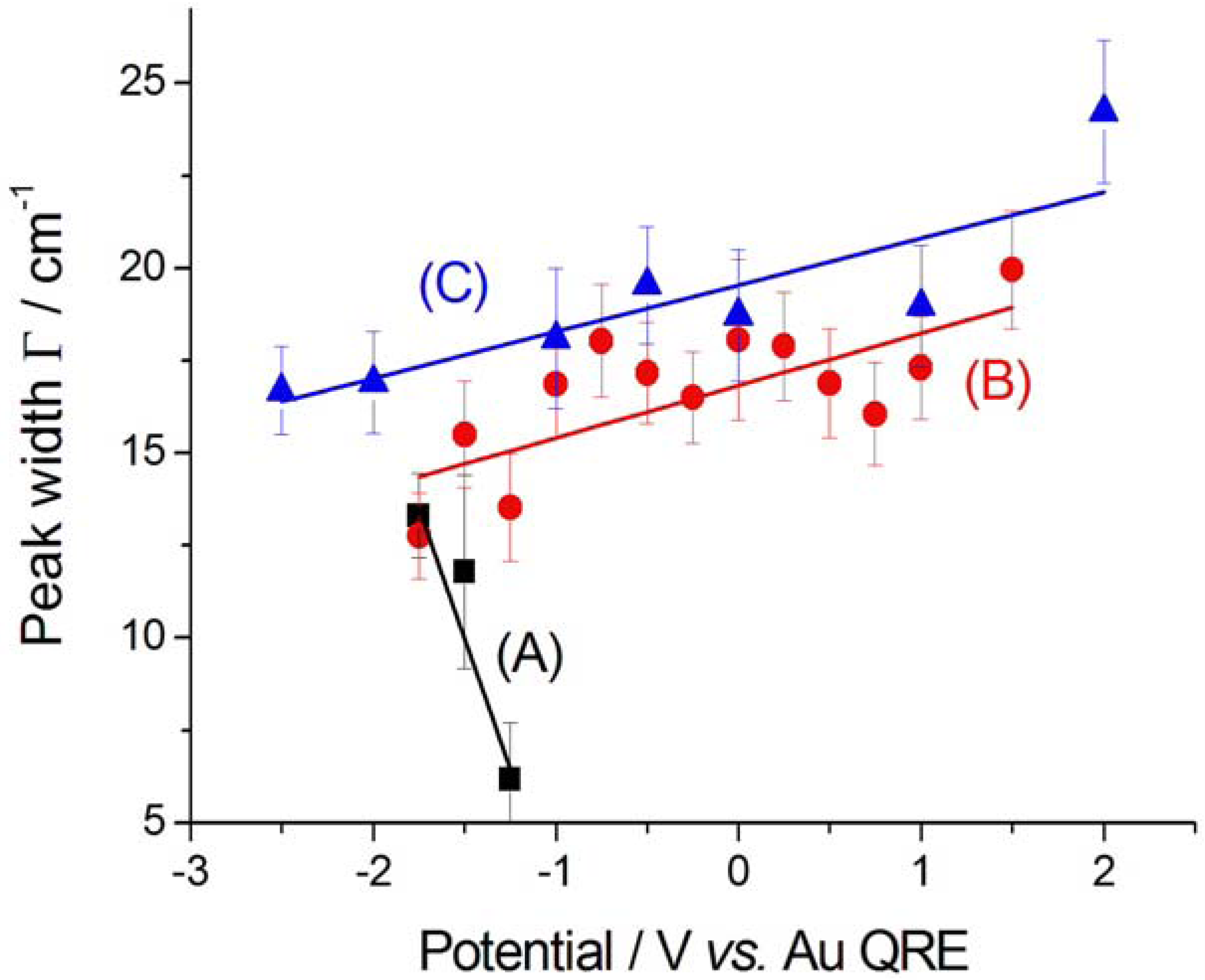
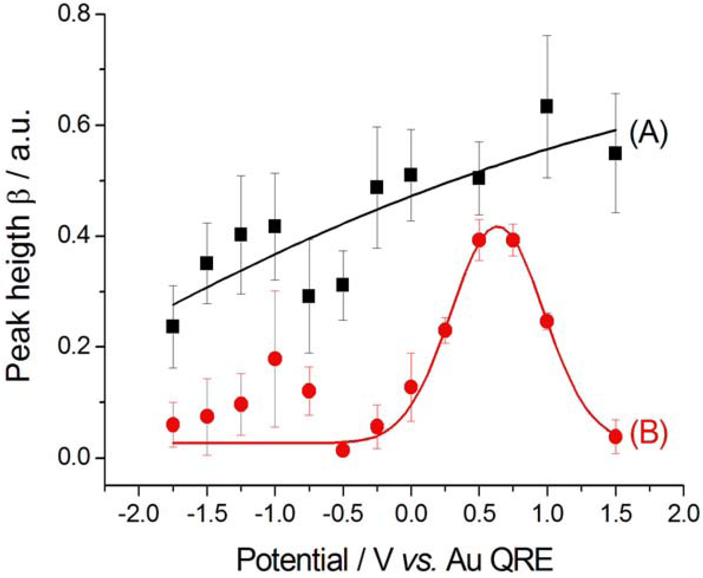
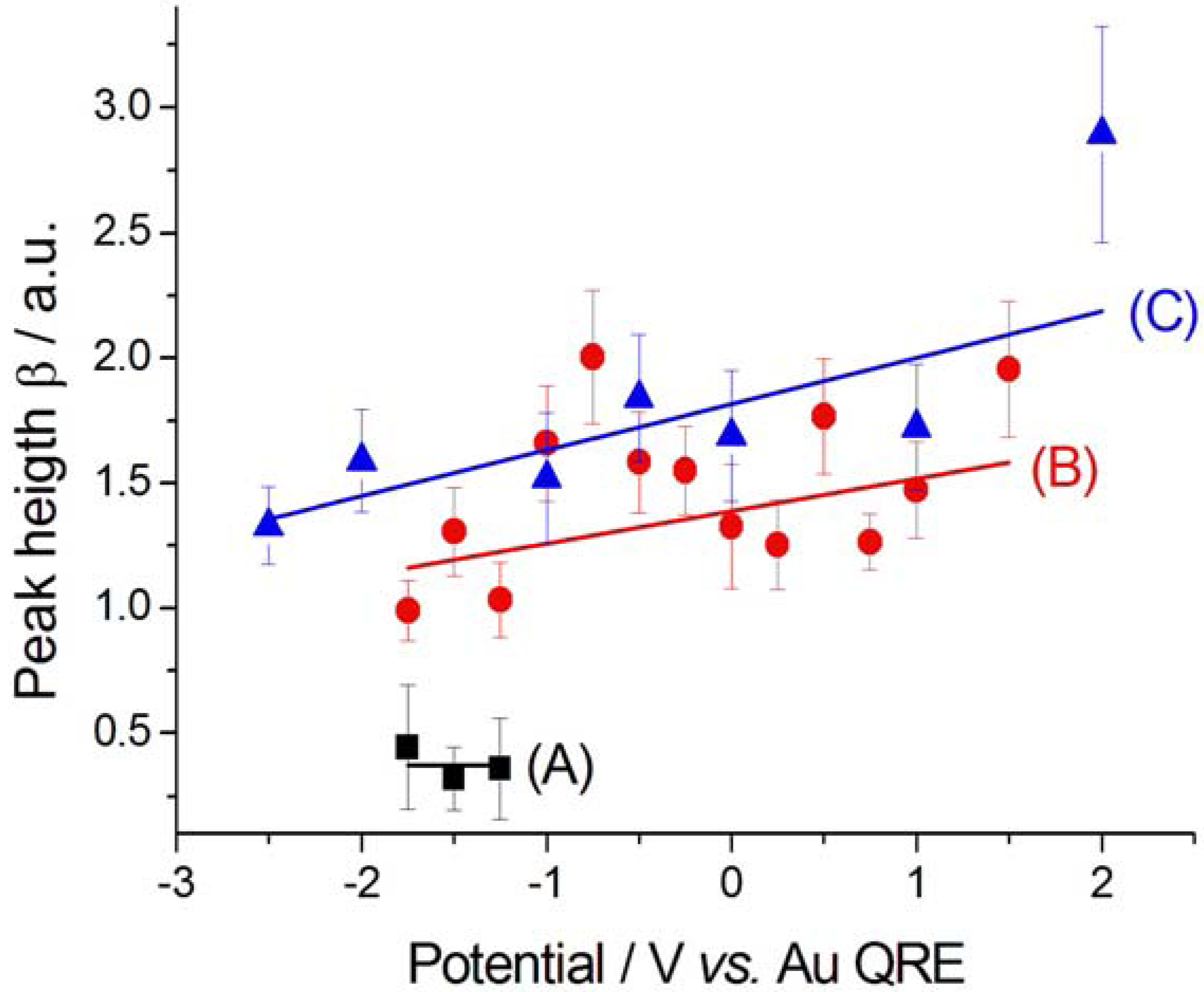
  is the height of the Lorentzian peak above background; (iv) Г is the peak width at half maximum; (v)
  can be understood as a linear approximation of a function describing the distortion of the lineshape from a pure Lorentzian (of course, a pure Lorentzian is obtained if δ = 0).
3.2. N-Resonance Model for SFG/DFG

 , by lengthy, but otherwise simple algebra one can derive:
 ,
,  ,
,  and
and  . The additional terms
  express the pairwise interference between couples of resonances.
3.3. Identification of a Guess Set of Parameters by Graphical Approach and Linear Least-Squares
 ; in fact, it can be proved that if
  and
and  ,
,  , where the subscripts “indep” and “coupled” refer to independent vs. couples resonances). The authors were not able to find a general approach to the problem of guess set identification in the case of strongly interacting resonances.
  of the parameter set . Once the subset is assigned, parameter δ can be obtained by solving the following linear least-squares problem: (i) the experimental (measured) array
  is transformed into
  , (ii) we adopt the transformed model:
  and (iii) identify δ with a linear least-squares fit of data
  with model
  . In this way, we have generated a guess set of parameters
  that is expected to be reasonably close to the global minimum (or, alternatively, to an NGM [23] whose physical meaning is clear). At this point, the original data set
  can be fitted with full model of Equation (2) by NLLS, employing as the starting parameter choice. The NLLS code hopefully will seek a sound minimum (in the sense defined above) along a reasonably hyperparabolic objective function.
3.4. Recovery of the “Physical” Parameter Set from the “Minimal-Correlation” Parameter Set
 can be recovered from the transformed parameter set
  through the algebraic manipulations explained below.
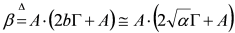
- (i) Since, in the case of Au,
![Molecules 17 07722 i041]() for Au, we can take:
for Au, we can take: ![Molecules 17 07722 i042]() , whence:
, whence: ![Molecules 17 07722 i043]() .
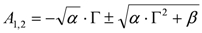
. - (ii) It is possible to use the approximation (i) to estimate A from β as follows:
![Molecules 17 07722 i044]() , whence:
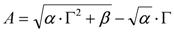
, whence: ![Molecules 17 07722 i045]() . Since physical solutions ought to be positive, it follows that:
. Since physical solutions ought to be positive, it follows that: ![Molecules 17 07722 i046]() .
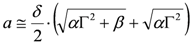
. - (iii) At this point, it is possible to estimate a from δ:
![Molecules 17 07722 i047]() , whence:
, whence: ![Molecules 17 07722 i048]()
- (iv) Once an estimate of a is available, it is possible to produce a better estimate of b by using the exact expression:
![Molecules 17 07722 i049]() . This updated value of b can, of course be used at point (ii) above and following to set up an iterative scheme.
. This updated value of b can, of course be used at point (ii) above and following to set up an iterative scheme.


4. Conclusions
Acknowledgements
References and Notes
- Electrodeposition from Ionic Liquids; Endres, F.; MacFarlane, D.; Abbott, A. (Eds.) Wiley-VCH: Weinheim, Germany, 2008.
- Nanbu, N.; Sasaki, Y.; Kitamura, F. In situ FT-IR spectroscopic observation of a room-temperature molten salt vertical bar gold electrode interphase. Electrochem. Commun. 2003, 5, 383–387. [Google Scholar] [CrossRef]
- Nanbu, N.; Kato, T.; Sasaki, Y.; Kitamura, F. In situ SEIRAS study of room-temperature ionic liquid vertical bar gold electrode interphase. Electrochemistry 2005, 7, 610–613. [Google Scholar]
- Santos, V.O.; Alves, M.B.; Carvalho, M.S.; Suarez, P.A.Z.; Rubim, J.C. Surface-enhanced Raman scattering at the silver electrode/ionic liquid (BMIPF6) interface. J. Phys. Chem. B 2006, 110, 20379–20385. [Google Scholar]
- Baldelli, S. Surface structure at the ionic liquid-electrified metal interface. Acc. Chem. Res. 2008, 41, 421–431. [Google Scholar] [CrossRef]
- Iwahashi, T.; Miyamae, T.; Kanai, K.; Seki, K.; Kim, D.; Ouchi, Y. Anion configuration at the air/liquid interface of ionic liquid [bmim]OTf studied by sum-frequency generation spectroscopy. J. Phys. Chem. B 2008, 112, 11936–11941. [Google Scholar] [CrossRef]
- Bozzini, B.; Bund, A.; Busson, B.; Humbert, C.; Ispas, A.; Mele, C.; Tadjeddine, A. An SFG/DFG investigation of CN− adsorption at an Au electrode in 1-butyl-1-methyl-pyrrolidinium bis(trifluoromethylsulfonyl) amide ionic liquid. Electrochem. Commun. 2010, 12, 56–60. [Google Scholar] [CrossRef]
- Bozzini, B.; Busson, B.; Humbert, C.; Mele, C.; Raffa, P.; Tadjeddine, A. Investigation of Au electrodeposition from [BMP][TFSA] room-temperature ionic liquid containing K[Au(CN)2] by in situ two-dimensional sum frequency generation spectroscopy. J. Electroanal. Chem. 2011, 661, 20–24. [Google Scholar] [CrossRef]
- Bozzini, B.; Sgura, I. Parameter functional dependence in an electro-chemical model: Theoretical and computational issues. Note Mat. 2007, 27, 39–52. [Google Scholar]
- Bozzini, B.; D’Urzo, L.; Mele, C.; Busson, B.; Humbert, C.; Tadjeddine, A. Doubly resonant sum frequency generation spectroscopy of adsorbates at an electrochemical interface. J. Phys. Chem. C 2008, 112, 11791–11795. [Google Scholar]
- Bozzini, B.; Mele, C.; Tondo, E. A SERS investigation of Cu electrodeposition in the presence of the model leveller 4-{2-[1-(2-cyanoethyl)-1,2,3,4-tetrahydroquinolin-6-yl]diazenyl} benzonitrile. Electrochim. Acta 2010, 55, 3279–3285. [Google Scholar] [CrossRef]
- Sur, U.K.; Lakshminarayanan, V. A study of the hydrophobic properties of alkanethiol self-assembled monolayers prepared in different solvents. J. Electroanal. Chem. 2004, 565, 343–350. [Google Scholar] [CrossRef]
- Zawisza, I.; Bin, X.; Lipkowski, J. Spectroelectrochemical studies of bilayers of phospholipids in gel and liquid state on Au(111) electrode surface. Bioelectrochemistry 2004, 63, 137–147. [Google Scholar] [CrossRef]
- MacFarlane, D.R.; Meakin, P.; Sun, J.; Amini, N.; Forsyth, M. Pyrrolidinium imides: A new family of molten salts and conductive plastic crystal phases. J. Phys. Chem. B 1999, 103, 4164–4170. [Google Scholar] [CrossRef]
- Lund, H. Cleavages and Deprotection. In Organic Electrochemistry; Lund, H., Hammerich, O., Eds.; Marcel Dekker Inc.: New York, NY, USA, 2001; p. 969. [Google Scholar]
- Bozzini, B.; Busson, B.; de Gaudenzi, G.P.; D’Urzo, L.; Mele, C.; Tadjeddine, A. An in situ SFG and SERS investigation into the electrodeposition of Au from Au(CN)2− and Au(CN)4− solutions. J. Electroanal. Chem. 2007, 602, 61–69. [Google Scholar] [CrossRef]
- Tadjeddine, A.; le Rille, A. Sum and Difference Frequency Generation at Electrode Surfaces. In Interfacial Electrochemistry: Theory, Experiment, and Applications; Wieckowski, A., Ed.; Marcel Dekker, Inc.: New York, NY, USA, 1999; p. 317. [Google Scholar]
- Bozzini, B.; Mele, C.; Fanigliulo, A.; Busson, B.; Vidal, F.; Tadjeddine, A. An SFG investigation of Au(111) and Au(210) electrodes in aqueous solutions containing KCN and cetylpyridinium chloride. J. Electroanal. Chem. 2004, 574, 85–94. [Google Scholar] [CrossRef]
- Bozzini, B.; D’Urzo, L.; Mele, C. Electrodeposition of Cu from cyanoalkaline solutions in the presence of CPC and PEG—An electrochemical and in situ SERS investigation. J. Electrochem. Soc. 2005, 152, C255–C264. [Google Scholar] [CrossRef]
- Bozzini, B.; D'Urzo, L.; Mele, C.; Romanello, V. A SERS investigation of cyanide adsorption and reactivity during the electrodeposition of gold, silver, and copper from aqueous cyanocomplexes solutions. J. Phys. Chem. C 2008, 112, 6352–6358. [Google Scholar] [CrossRef]
- Bozzini, B.; Giovannelli, G.; Natali, S.; Fanigliulo, A.; Cavallotti, P.L. Crystallographic structure of gold films electrodeposited at low current densities. J. Mater. Sci. 2002, 37, 3903–3913. [Google Scholar] [CrossRef]
- Humbert, C.; Busson, B.; Six, C.; Gayral, A.; Gruselle, M.; Villain, F.; Tadjeddine, A. Sum-frequency generation as a vibrational and electronic probe of the electrochemical interface and thin films. J. Electroanal. Chem. 2008, 621, 314–321. [Google Scholar] [CrossRef]
- Sgura, I.; Bozzini, B. Numerical issues related to the modelling of electrochemical impedance data by non-linear least-squares. Int. J. Non-Lin. Mech. 2005, 40, 557–570. [Google Scholar] [CrossRef]
- Sample Availability: Samples of the compounds quoted in the text are available from the mentioned vendors.
© 2012 by the authors; licensee MDPI, Basel, Switzerland. This article is an open-access article distributed under the terms and conditions of the Creative Commons Attribution license (http://creativecommons.org/licenses/by/3.0/).
Share and Cite
Bozzini, B.; Busson, B.; Gayral, A.; Humbert, C.; Mele, C.; Six, C.; Tadjeddine, A. In Situ Electrochemical SFG/DFG Study of CN− and Nitrile Adsorption at Au from 1-Butyl-1-methyl-pyrrolidinium Bis(trifluoromethylsulfonyl) Amide Ionic Liquid ([BMP][TFSA]) Containing 4-{2-[1-(2-Cyanoethyl)-1,2,3,4-tetrahydroquinolin-6-yl]diazenyl} Benzonitrile (CTDB) and K[Au(CN)2]. Molecules 2012, 17, 7722-7736. https://doi.org/10.3390/molecules17077722
Bozzini B, Busson B, Gayral A, Humbert C, Mele C, Six C, Tadjeddine A. In Situ Electrochemical SFG/DFG Study of CN− and Nitrile Adsorption at Au from 1-Butyl-1-methyl-pyrrolidinium Bis(trifluoromethylsulfonyl) Amide Ionic Liquid ([BMP][TFSA]) Containing 4-{2-[1-(2-Cyanoethyl)-1,2,3,4-tetrahydroquinolin-6-yl]diazenyl} Benzonitrile (CTDB) and K[Au(CN)2]. Molecules. 2012; 17(7):7722-7736. https://doi.org/10.3390/molecules17077722
Chicago/Turabian StyleBozzini, Benedetto, Bertrand Busson, Audrey Gayral, Christophe Humbert, Claudio Mele, Catherine Six, and Abderrahmane Tadjeddine. 2012. "In Situ Electrochemical SFG/DFG Study of CN− and Nitrile Adsorption at Au from 1-Butyl-1-methyl-pyrrolidinium Bis(trifluoromethylsulfonyl) Amide Ionic Liquid ([BMP][TFSA]) Containing 4-{2-[1-(2-Cyanoethyl)-1,2,3,4-tetrahydroquinolin-6-yl]diazenyl} Benzonitrile (CTDB) and K[Au(CN)2]" Molecules 17, no. 7: 7722-7736. https://doi.org/10.3390/molecules17077722
APA StyleBozzini, B., Busson, B., Gayral, A., Humbert, C., Mele, C., Six, C., & Tadjeddine, A. (2012). In Situ Electrochemical SFG/DFG Study of CN− and Nitrile Adsorption at Au from 1-Butyl-1-methyl-pyrrolidinium Bis(trifluoromethylsulfonyl) Amide Ionic Liquid ([BMP][TFSA]) Containing 4-{2-[1-(2-Cyanoethyl)-1,2,3,4-tetrahydroquinolin-6-yl]diazenyl} Benzonitrile (CTDB) and K[Au(CN)2]. Molecules, 17(7), 7722-7736. https://doi.org/10.3390/molecules17077722