Article

Handcrafted Electrocorticography Electrodes for a Rodent Behavioral Model

Department of Electrical Engineering, University of Texas Rio Grande Valley, Edinburg, TX 78539, USA
*
Author to whom correspondence should be addressed.
Technologies 2016, 4(3), 23; https://doi.org/10.3390/technologies4030023
Submission received: 3 February 2016 / Revised: 1 August 2016 / Accepted: 9 August 2016 / Published: 16 August 2016
(This article belongs to the Special Issue Brain-Machine Interface Technology)

Abstract

:
Electrocorticography (ECoG) is a minimally invasive neural recording method that has been extensively used for neuroscience applications. It has proven to have the potential to ease the establishment of proper links for neural interfaces that can offer disabled patients an alternative solution for their lost sensory and motor functions through the use of brain-computer interface (BCI) technology. Although many neural recording methods exist, ECoG provides a combination of stability, high spatial and temporal resolution with chronic and mobile capabilities that could make BCI systems accessible for daily applications. However, many ECoG electrodes require MEMS fabricating techniques which are accompanied by various expenses that are obstacles for research projects. For this reason, this paper presents an animal study using a low cost and simple handcrafted ECoG electrode that is made of commercially accessible materials. The study is performed on a Lewis rat implanted with a handcrafted 32-channel non-penetrative ECoG electrode covering an area of 3 × 3 mm2 on the cortical surface. The ECoG electrodes were placed on the motor and somatosensory cortex to record the signal patterns while the animal was active on a treadmill. Using a Tucker-Davis Technologies acquisition system and the software Synapse to monitor and analyze the electrophysiological signals, the electrodes obtained signals within the amplitude range of 200 µV for local field potentials with reliable spatiotemporal profiles. It was also confirmed that the handcrafted ECoG electrode has the stability and chronic features found in other commercial electrodes.
Keywords:
ECoG; PDMS; microwire; MEMS

Graphical Abstract

1. Introduction

In the study of neuroscience, there is a significant amount of interest in determining the mechanisms that explain the relationship between neural interactions in the brain and physical movements, or behaviors. Being able to measure brain signals to understand these mechanisms will allow to treat numerous diseases and substantially increase the quality of recovery for patients suffering from nervous tissue damage [1,2,3,4,5]. Furthermore, identifying neural functions by means of cortical maps can ease the establishment of proper links for neural interfaces that can offer disabled patients an alternative solution for their lost sensory and motor functions through the use of brain-computer interface (BCI) technology [6,7,8,9]. Several recording methods such as electroencephalography (EEG), electrocorticography (ECoG), magnetoencephalography (MEG), positron emission tomography (PET), and functional magnetic resonance imaging (fMRI) have proven to be potentially useful in the implementation of BCI [10,11,12,13,14]. However, due to not having considerable temporal resolution and being large systems, MEG, fMRI, and PET are not practical for continuous recording of electrical signals from neurons. Alternatively, EEG and ECoG have the portability and are comparably less expensive. These interfaces extract neural activity with the use of electrodes, which have advanced the performance of BCI and neuroprosthetics.
EEG is a commonly known recording technique for BCI applications due to its low cost, portability, and non-invasiveness. This method measures the activity from a large population of neurons by attaching electrodes to the scalp of a subject. As a consequence, the impedance of the distance between the cortical tissue and the electrodes force the EEG to have a low spatial resolution [10,15]. Another type of recording technology is the Utah Intracortical Electrode Array (UIEA) which has allowed implanting a large number of microelectrodes into a small area of the cortex due to its micromachined structure. This technique has been implemented in BCI systems for its ability to provide high temporal and spatial resolution and capture both action potentials and local field potentials by allowing microelectrodes to be placed close to small groups of neurons. With this information, UIEA has enabled individuals with illnesses, such as tetraplegia, to gain control over technologies, including neuroprosthetics [16,17,18,19]. However, this electrode array has also proven to be impractical due to its lack of reliability and invasive procedure. Attention has converged to electrocorticography (ECoG), a minimally invasive method that records over the cortical surface of the brain by surgically placing an array of electrodes underneath the skull. By direct comparison with EEG electrodes which obtain signals in the 5–10 µV range from scalp electrodes, ECoG electrodes detect signals from around 50 µV to over 100 µV. The bandwidth of EEG is limited to about 50 Hz, since ECoG is placed on the surface of the cortex it has a higher frequency bandwidth ranging between 40 to several hundred Hz. The ECoG allows the obtaining of accurate signal source localization because it achieves a spatial resolution in the millimeter range compared to the centimeter range with EEG neural activity. For these reasons, ECoG has become a preferable alternative approach to recording brain activity for BCI applications in numerous occasions [20,21,22].
Advances in ECoG has allowed the electrode arrays to be placed closer to neurons for an improved spatial and temporal resolution. With the use of micromachining, contemporary ECoG electrodes are highly flexible with a higher electrode density and has the feasibility to surgically place the electrodes onto the cortical surface. This technology has enabled advanced investigations in patients with epilepsy and similar diseases, demonstrating a feasibility to facilitate interactions with external devices, and allowance for obtaining larger local field potentials (LFP) maps [23,24,25,26,27,28]. Although these valuable advances have improved many applications, ECoG, along with all other methods, comes with its particular set of trade-offs. Even though the safety of ECoG has also been improved, there remain concerns with invasive techniques in regards to their biocompatibility, the level of invasiveness, and conformability with the architecture of the brain [5,29,30]. Furthermore, this technology requires MEMS fabrication techniques which grant it similar difficulties and expenses found in fabricating microdevices. Micromachining electrode arrays in the case by case basis to control the trade-off characteristics and obtain certain capabilities for experiments having specific requirements makes the technique delicate and expensive for various applications.
The standard ECoG technique has grown to be weakly invasive and vastly applicable to a majority of BCI applications. For these reasons, the device presented in this paper will describe an easier and faster fabrication process of obtaining an ECoG electrode array that will grant users the freedom to design unique basic configurations of the electrode array with commercially available materials for various research projects. The ECoG electrode developed with this process will be handcrafted, robust, and have similar spatial and temporal resolution as other modern ECoG electrodes [31]. The quality of the electrode will be presented through the results obtained from the neural activity of Lewis rats on a treadmill to demonstrate that the handcrafted electrode does provide a reliable performance similarly seen in other ECoG electrodes.

2. Materials and Methods

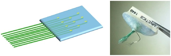
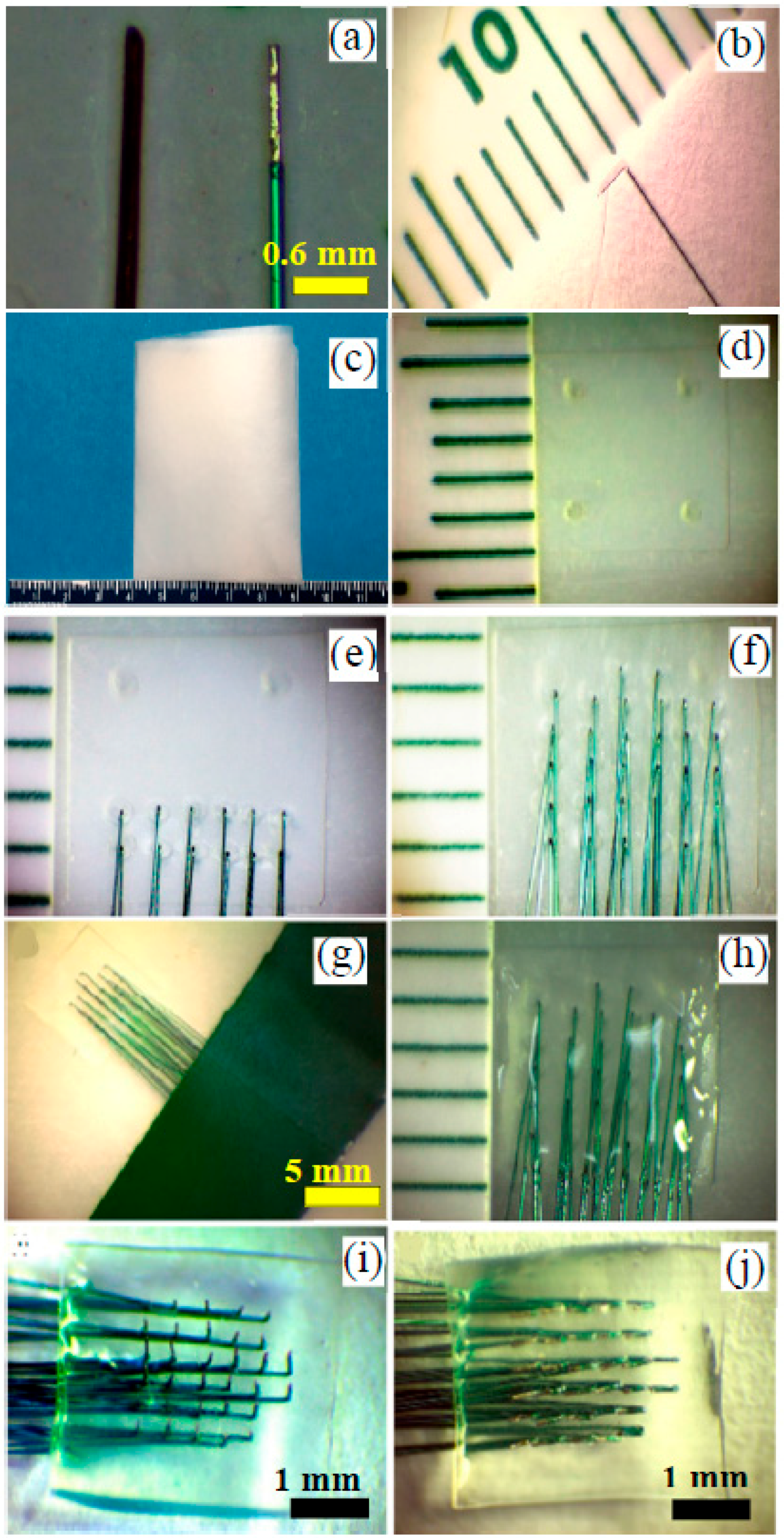
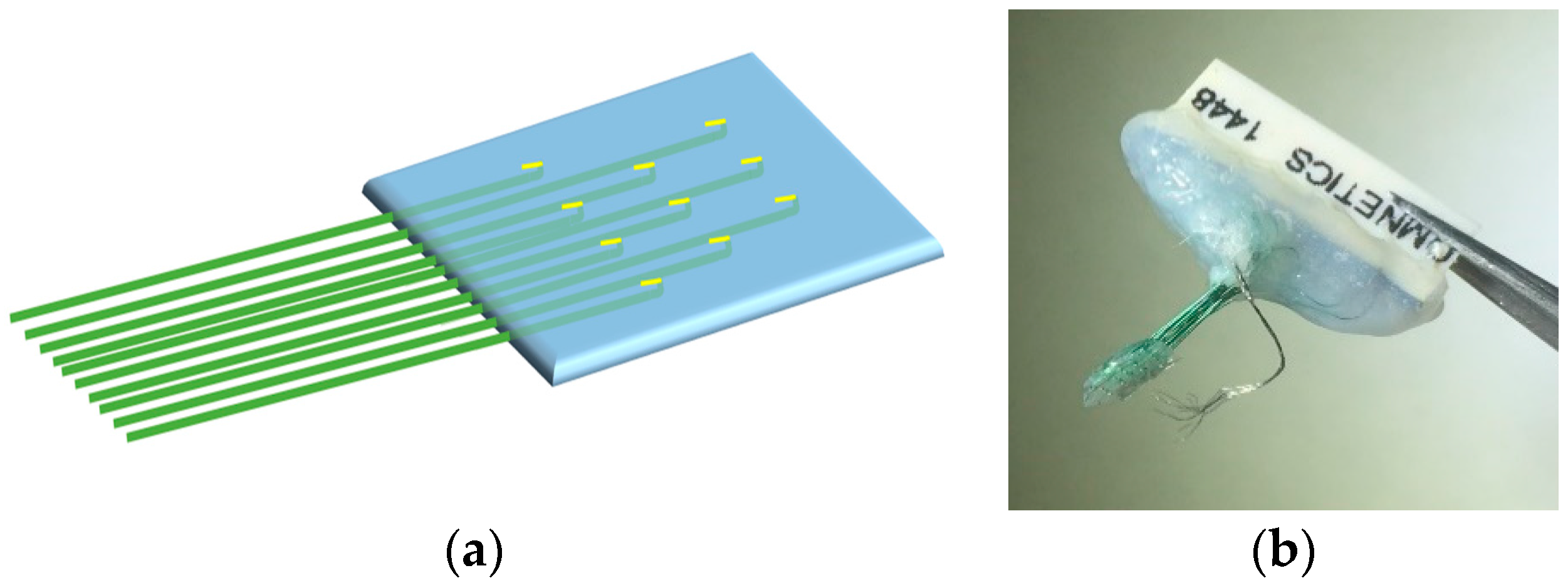
2.1. Fabrication of Handcrafted ECoG Electrode

To make the handcrafted ECoG electrode, commercially available microwires of 75 µm in diameter (Stablohm 800A, California fine wire, Grover Beach, CA, USA) was used as the probes in our device. The microwire was insulated by heavy poly-nylon, and other material specification can be found on the company’s website [32]. The impedance of the developed ECoG electrodes was measured around 500 KΩ at 1 KHz. The stablohm wire was cut into 32 segments of 15 mm in length. With the use of a ruler, 1 mm of insulation was peeled off at one end of each wire. A comparison of the stablohm microwire with a human hair is presented in Figure 1a, in which the microwire is uninsulated 1 mm in length. Then, the uninsulated part of each wire was bent at an angle 90° with the help of tweezers under the microscope resulting in Figure 1b. After all 32 wire had been prepared, a paraffin wax film (Parafilm M Laboratory Film, Bemis Corporate, Neenah, WI, USA) was folded to make six layers with an area of 50 × 50 mm2 (Figure 1c). An area of 3 × 3 mm2 was marked on top of the wax film, which was used to guide the placement of the wires into a square shape. The marked area was then covered with a thin Polydimethylsiloxane (PDMS) layer within an area of 5 × 5 mm2 on the wax film (Figure 1d). The wax film allowed to easily separate a fabricated ECoG at the final stage because it is not adhesive to the PDMS layer. The wires were then placed row by row on the thin PDMS film by inserting the curved sides of the wire within the marked area using tweezers, making them parallel and kept apart at equal distances of 0.6 mm as demonstrated in Figure 1e,f. Once all 32 wires were inserted into the wax film, the remaining parts of the wires were held in place using a tape. The tape was placed on the wax film, as shown in Figure 1g. Then the 186 Sylgard base (Dow Corning Corporation, Midland, MI, USA) and curing agent were mixed at a ratio of 10:1 and kept in a vacuum chamber for 30 min until all visible bubbles had disappeared. The PDMS was applied in small amounts over the wires that were inserted into the wax film through the thin PDMS film. Then, the device was placed in the oven for 20 min at 50 °C, resulting in Figure 1h. This low temperature was required to keep the wax film stable. The tape was then removed, and the wax film was separated from the device. Figure 1i shows the bottom view of the device after removing the wax film. Then, the tip of the wires were further bent with tweezers and laid along the PDMS film as shown in Figure 1j. This last step finalized the electrode array to a thickness less than 1 mm. The next step was to solder the other ends of the wires to the 32 pin Omnetics Connector (Nano Strip Connector, A79022-001, Omnetics, Minneapolis, MN, USA). After soldering had been done, epoxy glue was applied on the pins and through the wires that had been connected to the soldering pins. The glue was then applied in between the pin gaps and filled up all the empty spaces. Figure 2a shows a schematic view of the stage of Figure 1j for better understanding the structure and Figure 2b shows the final device which is ready for implantation.

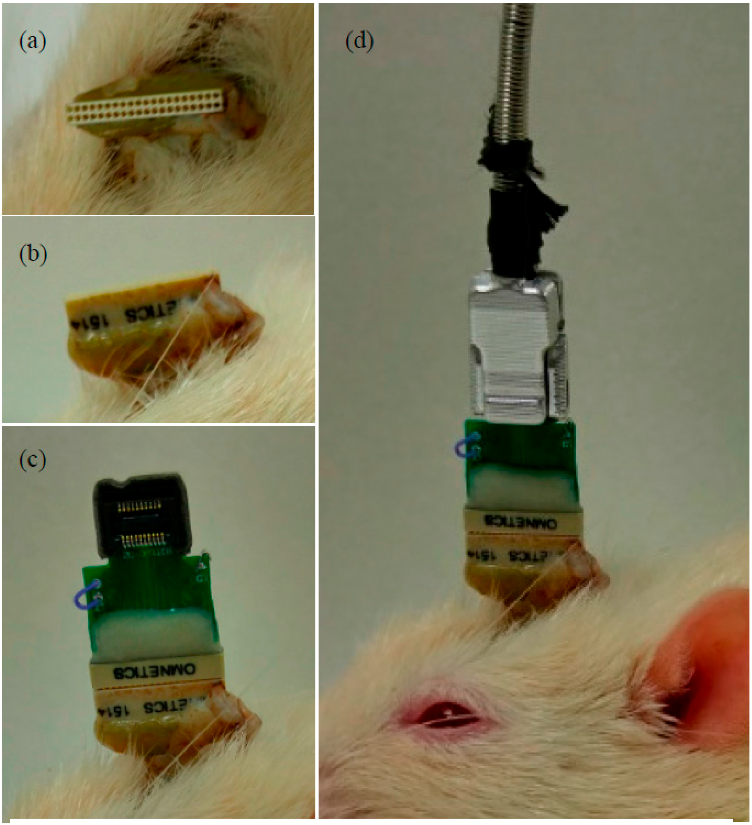
2.2. Implantation of Handcrafted ECoG Electrodes

A Lewis rat underwent implantation surgery in aseptic conditions at the UTRGV Animal Facility. Prior to implantation, the rat was placed into an induction chamber, and Isoflurane (5.0%) was used to induce anesthesia followed by maintenance of anesthesia (1.0%–2.0%) in oxygen until unconscious. The surgery location (the top of the rat’s head from between the eyes to behind the ears) was shaved and cleaned using a betadine scrub and isopropyl alcohol using electric barber’s clippers [33]. Its maxillary central incisors were hooked into a gas mask through which it continued to receive small doses of anesthesia [34]. Then, the rat was mounted in stereotaxic ear bars. It was secured to a surgery table, and its body temperature was regulated with a hot pad. On top of the head, two half circles from the midline outwards were partially cut removing the scalp. The bone surface was disinfected and cleaned using hydrogen peroxide. The bone was dried to make the cranial sutures more clearly visible. Screw holes were drilled into the bone, and stainless steel screw electrode was placed systematically on the brain’s left hemisphere. For the 5 × 5 mm2 device, a 6 × 6 mm2 craniotomy must be made [35]. Before drilling the cranium, UV-curable dental acrylic was applied to the periphery of the craniotomy site while it was still dry and not in danger of touching the dura or pia. The dura was kept well hydrated with artificial CSF or Saline. To implant the ECoG device, a stereotaxic arm was placed over the open skull, and the electrode was secured to the arm using sterile tape making sure that the electrode sites were facing downward and made contact with the dura surface. The ground wire was connected to the ground screw by wrapping around at least three times over and under itself. Small pieces of saline soaked Gelfoam was placed surrounding the electrode where there was dura or pia exposed. A small amount of saline soaked Gelfoam was placed to cover the top of the thin film electrode. UV-curable dental acrylic was applied to the top of the Gelfoam and was used to create a stable head cap. The acrylic was applied directly to the thin film cable covering it until the connector is reached. After the dental acrylic was completely hardened, the skin was sutured tightly around the head-cap and the animal was removed from the stereotaxic frame. Antibiotic ointment was applied copiously around the wound. Some antibiotic was placed into the ear canal for the bleeding from the ears. All surgical procedures were performed in accordance with the Guide for the Care and Use of Laboratory Animals of the Institute of Laboratory Animal Resources, Commission on Life Sciences, National Research Council (National Academy Press, Washington, DC, USA, 1996) and were reviewed and approved by the Institutional Animal Care and Use Committee UTRGV.

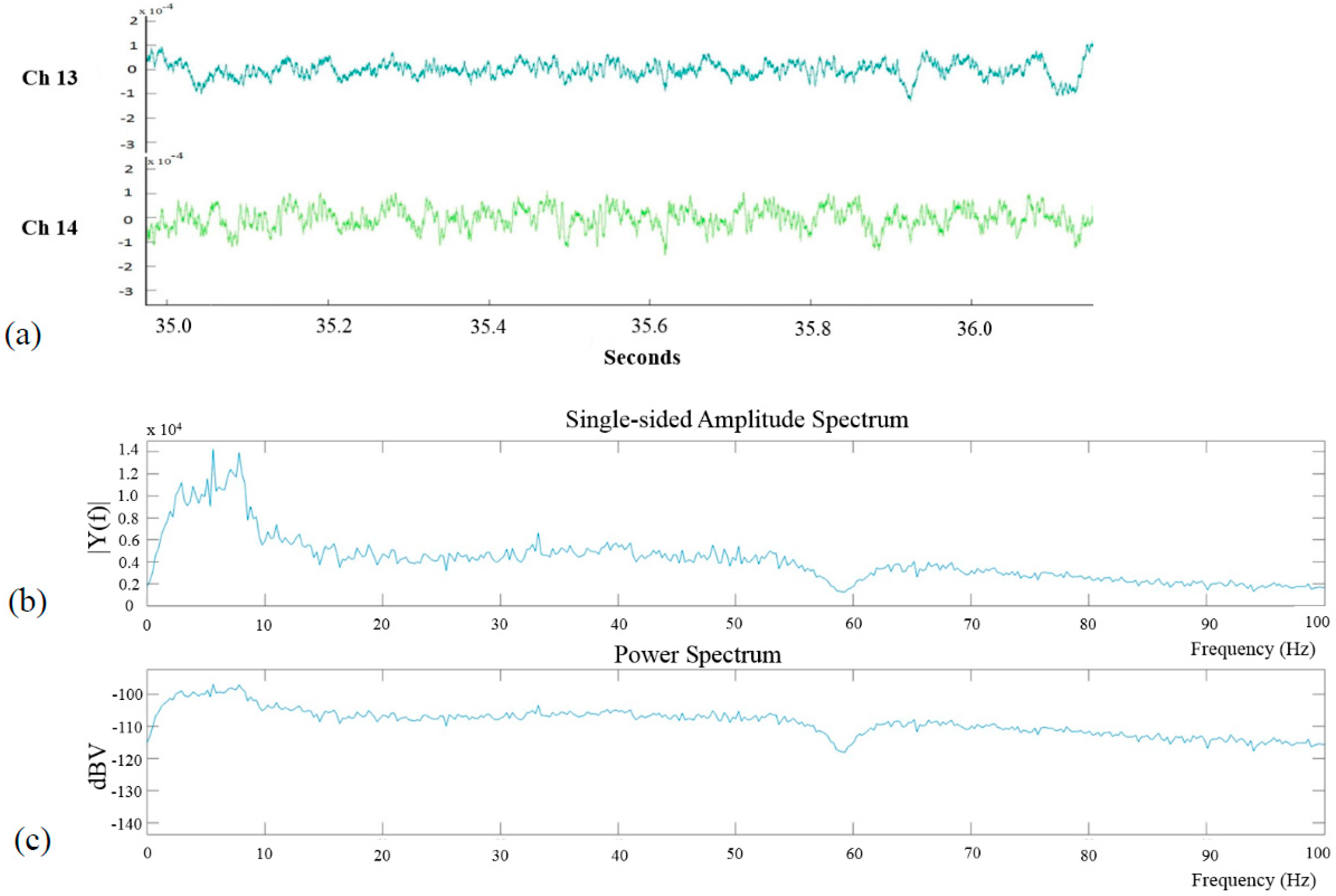
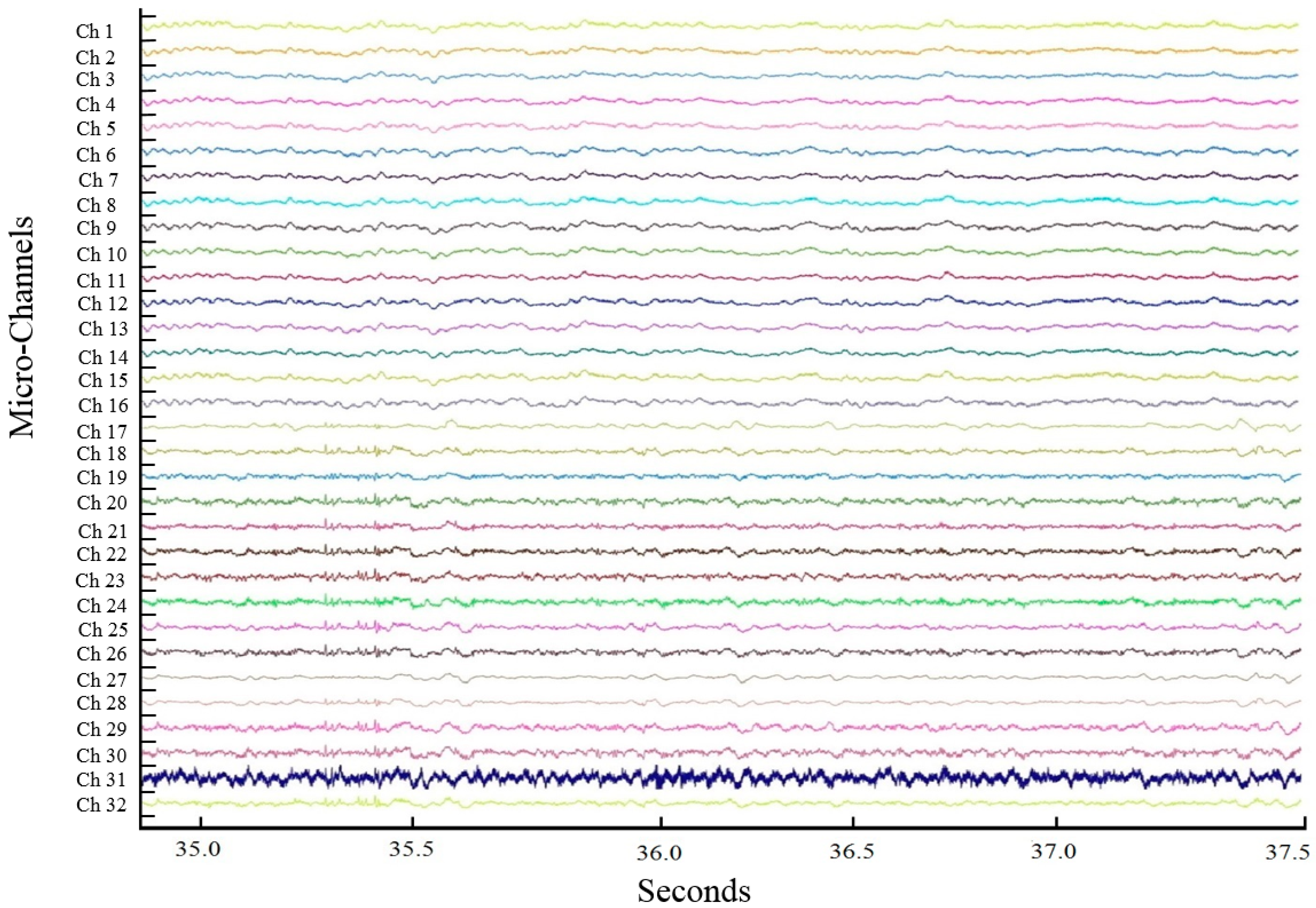
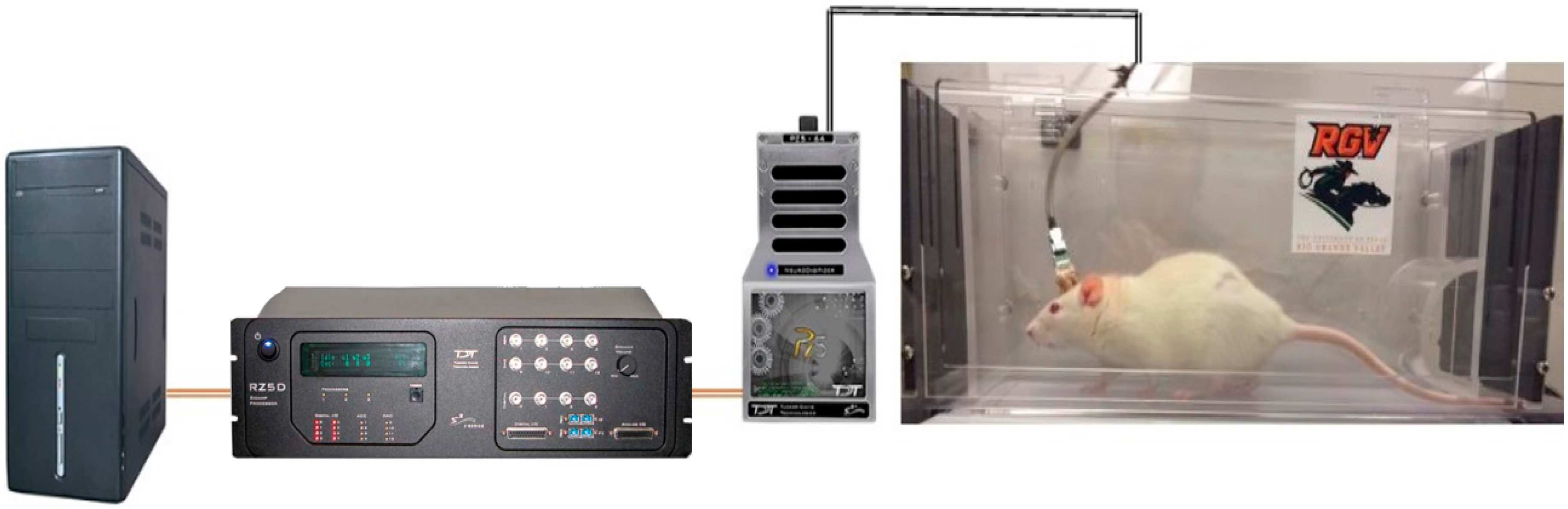
3. ECoG Acquisition Setup and Result

We were able to customize signals by linking components to create custom processing circuits using TDT 32-channel electrophysiological signal acquisition system (Tucker-Davis Technologies, Alachua, FL, USA). In order to remove noise from the signals, we first used a notch filter for removing 60 Hz and similar interferences from the waveforms and re-referenced them to one of the 32 channels. Next, we band-pass filtered the signal between 300 Hz and 7000 Hz. This signal processing technique greatly improved the quality of ECoG signal analyses. Figure 3 shows the configuration of the system from the animal on a treadmill to the workstation computer to monitor and analyze the electrophysiological signals. The detail views of the connection between ECoG electrodes and TDT zip clip is shown in Figure 4.
In total, six animals were involved for this project. Recorded signals were amplified and digitized in PZ5 and then transmitted to the RZ5 BioAmp Processor for further processing via an isolated, noiseless fiber optic connection. The optical interface ensured fast and reliable data transfer from the PZ5 to RZ5 and a workstation computer. All experiments resulted in comparable signals to each other suggesting that the fabrication of our handcrafted device can provide a desirable yield. Due to the similarity of the results from each experiment, the dataset from an individual experiment was analyzed to describe the details that was observed from each dataset obtained from the rest of the experiments. By using TDT 32-channel acquisition system and Synapse software, we were able to record brain signals from 32-channel ECoG electrodes. Channel 13 and 14 are shown in Figure 5a to present a couple clear examples of the signals obtained from every channel. These two signals show that the unit of the y-axis was 100 µV, and peak-to-peak amplitudes were shown around 200 µV. This plot shows a 1 s period signal pattern which demonstrated the traditional local field potential patterns [36,37,38,39,40]. Using Synapse, TDT’s graphical design software, we could control the signal presentation and data acquisition, customize the function of each signal processing module, and control timing, triggering, and data storage. Synapse communicated directly with TDT hardware for fast, precisely timed operations. When an experiment is fully configured and saved, the data can be displayed in either preview or record mode. In Preview mode, we adjusted plots and changed the sorting parameters and runtime settings without any of the data being permanently stored in the data tank. For the plots in Figure 5b,c, a notch filter to remove 60 Hz noise from channel 13 was used during the recording sessions which was represented as a deep dent at 60 Hz in the frequency spectrum. Moreover, the amplitude between 0 and 10 Hz, in Figure 5b, is within a normal range for local field potentials confirming the signals to be neural signals. Figure 6 shows all neural signals from 31 electrodes of the ECoG while the free behaving animal model was walking on a treadmill within the testing area shown in Figure 3. One out of 32 channels (Channel 2) was used as a digital reference signal to remove any possible noise. The differential signals measured between 31-channel signals and a reference channel signal improved the signal quality. The differential recordings selectively amplify the difference in the signal from the ECoG electrodes while suppressing the common signal, i.e., the background noise.

4. Discussion

In the present study, we produced a handcrafted 32-channel ECoG electrode array for recording neural signals. We implanted this device on a rat’s cortical surface and obtained reliable spatiotemporal profiles. Since the device is handcrafted, it can be easily modified in the fabrication process. The device is also very simple, adjustable, minimally-invasive, and quick to fabricate with a minimum of expense. The size of the device can also be controlled by increasing or decreasing the length, diameter, and a number of the wires which could be applied to investigate the puzzling concept of physical structures affecting the quality of LFPs in electrodes arrays [41,42,43]. Without the need for cleanroom facilities, this device can be fabricated and modified to fit and possibly improve on different applications, such as BCI systems [44,45]. Since the electrode is handcrafted, users can design ECoGs with higher electrode density without any further complication and microfabrication limitation. The flexibility of the device design and fabrication is highly required for multidisciplinary biological applications. We can focus on the biological mechanism in the complicated multidisciplinary research without any interruption, even if the device dimension should be modified significantly. The short turnaround time of the modification and fabrication of the handcrafted ECoG is especially preferable when we pioneer a new approach to a research.
The biocompatibility of the ECoG electrode is justified by using PDMS, a suitable base material for its durability and biocompatibility. As a biocompatible material, PDMS has been used in a wide range of clinical applications and can be listed in three different categories, such as a structure itself as part of the device, an insulator, and a liquid form. PDMS cuff electrodes have been used on the extradural sacral root to sense the bladder response to stimulation in patients [46,47,48]. The biocompatibility of the other material used for our device, stablohm wire, has been proven through its use on animal studies in the neuroscience field. There are many reports demonstrating the use of stablohm wires for biomedical research. Stablohm wires have been implemented into tetrode technologies to act as low impedance wires and isolate signals of extracellular spikes [49,50,51,52,53]. Other research have also used stablohm wires as recording electrodes in their electrode arrays and implanted into different regions of an animal’s brain for neural recordings [54,55,56,57,58,59,60]. Eight different stablohm wires have been supported by California Fine Wire (www.calfinewire.com) based on the variation of the electrical resistance. We have used stablohm 800 A wire for its higher mechanical stiffness by referencing Young’s modulus that relates to a more rigid wire that helps ease the fabrication of the device. Additionally, our device was validated after four weeks which showed no noticeable changes in the quality of the signals or effect on the animal models. However, future studies will take place to demonstrate the feasibility of the device for chronic recording with a higher density of electrodes.
We have developed an animal model using our ECoG electrode to investigate the possibility to match the behavioral patterns of animals while recording the ECoG signals. The ECoG electrodes were placed on the motor and somatosensory cortex and the related neural signals have been recorded. Currently, we are further investigating an acquired database to find specific electrophysiological patterns from animal behavior. This requires intensive computational neuroscience approach to screen out critical behavioral data from the immense neural data. The next goal and future direction of the presented work is pursuing further analysis of the acquired neural signals, possibly with a collaboration of a computational neuroscience lab for higher level analysis.

5. Conclusions

The presented handcrafted 32-channel ECoG electrode brings ECoG applications closer to daily implementations. With the quick, adjustable, low cost, and uncomplicated fabricating process, this device could be used for many research purposes. Being constructed from a commercially available material and not requiring micromachining techniques, a user can also make modifications to the design of the device to fit onto various cortical surfaces. After implementing the electrode onto a Lewis rat, it was confirmed that it remained stable and non-penetrative with the high spatial and temporal features also observed from commercial electrodes.
The data collected from our rat model using a TDT signal acquisition system suggests that the handcrafted electrode does have the capabilities to provide reliable readings that can be used in neuroscience applications. The traditional amplitude range of the signals obtained from the electrodes have similar characteristics as reported from other microelectrodes, which makes the device a considerable candidate for numerous applications. Further studies will focus on increasing its electrode density which can generate sophisticated neural data comparable with animal’s behavioral patterns.

Acknowledgments

The authors thank Victor Rush at Tucker-Davis Technologies (TDT) for his technical support and guidance in electrophysiological recording setup and invaluable discussion on our recording data of awake, behaving animals. Financial support from the University of Texas System (UT System), UTRGV STARTS, is gratefully acknowledged.

Author Contributions

The main authors and researchers, Nishat Tasnim and Ali Ajam, developed the devices and performed overall project management. Raul Ramos, Mukhesh K. Koripalli, and Manisankar Chennamsetti recorded and analyzed neural signals. Yoonsu Choi performed animal surgeries. All authors have read and approved the final manuscript.

Conflicts of Interest

The authors declare no conflict of interest.

References

  1. Navarro, X.; Krueger, T.B.; Lago, N.; Micera, S.; Stieglitz, T.; Dario, P. A critical review of interfaces with the peripheral nervous systemfor the control of neuroprostheses and hybrid bionic systems. J. Peripher. Nerv. Syst. 2005, 10, 229–258. [Google Scholar] [CrossRef] [PubMed]
  2. Sanchez, J.C.; Gunduz, A.; Carney, P.R.; Principe, J.C. Extraction and localization of mesoscopic motor control signals for human ECoG neuroprosthetics. J. Neurosci. Methods 2008, 167, 63–81. [Google Scholar] [CrossRef] [PubMed]
  3. Schalk, G.; McFarland, D.J.; Hinterberger, T.; Birbaumer, N.; Wolpaw, J.R. BCI2000: A general-purpose brain-computer interface (BCI) system. IEEE Trans. Biomed. Eng. 2004, 51, 1034–1043. [Google Scholar] [CrossRef] [PubMed]
  4. Nagasaka, Y.; Shimoda, K.; Fujii, N. Multidimensional Recording (MDR) and Data Sharing: An Ecological Open Research and Educational Platform for Neuroscience. PLoS ONE 2011, 6, e22561. [Google Scholar] [CrossRef] [PubMed]
  5. Khodagholy, D.; Doublet, T.; Quilichini, P.; Gurfinkel, M.; Leleux, P.; Ghestem, A.; Ismailova, E.; Hervé, T.; Sanaur, S.; Bernard, C.; et al. In vivo recordings of brain activity using organic transistors. Nat. Commun. 2013, 4, 1575. [Google Scholar] [CrossRef] [PubMed]
  6. Wang, W.; Degenhart, A.D.; Collinger, J.L.; Vinjamuri, R.; Sudre, G.P.; Adelson, P.D.; Holder, D.L.; Leuthardt, E.C.; Moran, D.W.; Boninger, M.L.; et al. Human motor cortical activity recorded with micro-ECoG electrodes during individual finger movements. In Proceedings of the Annual International Conference of the IEEE Engineering in Medicine and Biology Society, Minneapolis, MN, USA, 3–6 September 2009.
  7. Toda, H.; Suzuki, T.; Sawahata, H.; Majima, K.; Kamitani, Y.; Hasegawa, I. Simultaneous recording of ECoG and intracortical neuronal activity using a flexible multichannel electrode-mesh in visual cortex. NeuroImage 2011, 54, 203–212. [Google Scholar] [CrossRef] [PubMed]
  8. Liu, H.; Tanaka, N.; Stufflebeam, S.; Ahlfors, S.; Hämäläinen, M. Functional mapping with simultaneous MEG and EEG. J. Vis. Exp. 2010. [Google Scholar] [CrossRef] [PubMed]
  9. Schwartz, A.B.; Cui, X.T.; Weber, D.J.; Moran, D.W. Brain-controlled interfaces: Movement restoration with neural prosthetics. Neuron 2006, 52, 205–220. [Google Scholar] [CrossRef] [PubMed]
  10. Hill, N.J.; Lal, T.N.; Schröder, M.; Hinterberger, T.; Widman, G.; Elger, C.E.; Schölkopf, B.; Birbaumer, N. Classifying event-related desynchronization in EEG, ECoG and MEG signals. In Pattern Recognition; Franke, K., Müller, K.-L., Nickolay, B., Schäfer, R., Eds.; Springer Berlin Heidelberg: Heidelberg, Germany, 2006; pp. 404–413. [Google Scholar]
  11. Lee, A.K.; Larson, E.; Maddox, R.K. Mapping cortical dynamics using simultaneous MEG/EEG and anatomically-constrained minimum-norm estimates: An auditory attention example. J. Vis. Exp. 2012. [Google Scholar] [CrossRef] [PubMed]
  12. Hill, N.J.; Gupta, D.; Brunner, P.; Gunduz, A.; Adamo, M.A.; Ritaccio, A.; Schalk, G. Recording human electrocorticographic (ECoG) signals for neuroscientific research and real-time functional cortical mapping. J. Vis. Exp. 2012. [Google Scholar] [CrossRef] [PubMed]
  13. Conner, C.R.; Ellmore, T.M.; Pieters, T.A.; DiSano, M.A.; Tandon, N. Variability of the Relationship between Electrophysiology and BOLD-fMRI across Cortical Regions in Humans. J. Neurosci. 2011, 31, 12855–12865. [Google Scholar] [CrossRef] [PubMed]
  14. Zhu, Y.; Xu, K.; Xu, C.; Zhang, J.; Ji, J.; Zheng, X.; Zhang, H.; Tian, M. PET Mapping for Brain-Computer-Interface-Based Stimulation in a Rat Model with Intracranial Electrode Implantation in the Ventro-posterior Medial Thalamus. J. Nucl. Med. 2016, 57, 1141–1145. [Google Scholar] [CrossRef] [PubMed]
  15. Pistohl, T.; Ball, T.; Schulze-Bonhage, A.; Aertsen, A.; Mehring, C. Prediction of arm movement trajectories from ECoG-recordings in humans. J. Neurosci. Methods 2008, 167, 105–114. [Google Scholar] [CrossRef] [PubMed]
  16. Maynard, E.M.; Nordhausen, C.T.; Normann, R.A. The Utah intracortical electrode array: A recording structure for potential brain-computer interfaces. Electroencephalogr. Clin. Neurophysiol. 1997, 102, 228–239. [Google Scholar] [CrossRef]
  17. Masse, N.Y.; Jarosiewicz, B.; Simeral, J.D.; Bacher, D.; Stavisky, S.D.; Cash, S.S.; Oakley, E.M.; Berhanu, E.; Eskandar, E.; Friehs, G.; et al. Non-causal spike filtering improves decoding of movement intention for intracortical BCIs. J. Neurosci. Methods 2014, 236, 58–67. [Google Scholar] [CrossRef] [PubMed]
  18. Perge, J.A.; Zhang, S.; Malik, W.Q.; Homer, M.L.; Cash, S.; Friehs, G.; Eskandar, E.N.; Donoghue, J.P.; Hochberg, L.R. Reliability of directional information in unsorted spikes and local field potentials recorded in human motor cortex. J. Neural Eng. 2014, 11, 046007. [Google Scholar] [CrossRef] [PubMed]
  19. Leavitt, M.L.; Pieper, F.; Sachs, A.; Joober, R.; Martinez-Trujillo, J.C. Structure of spike count correlations reveals functional interactions between neurons in dorsolateral prefrontal cortex area 8a of behaving primates. PLoS ONE 2013, 8, e61503. [Google Scholar] [CrossRef] [PubMed]
  20. Ponce, P.; Molina, A.; Balderas, D.C.; Grammatikou, D. Brain Computer Interfaces for Cerebral Palsy. InTech 2014. [Google Scholar] [CrossRef]
  21. Wilson, J.A.; Felton, E.A.; Garell, P.C.; Schalk, G.; Williams, J.C. ECoG factors underlying multimodal control of a brain–computer interface. IEEE Trans. Biomed. Eng. 2006, 14, 246–250. [Google Scholar] [CrossRef] [PubMed]
  22. Pashaie, R.; Anikeeva, P.; Lee, J.H.; Prakash, R.; Yizhar, O.; Prigge, M.; Chander, D.; Richner, H.J.; Williams, J. Optogenetic Brain Interfaces. IEEE Rev. Biomed. Eng. 2014, 7, 3–30. [Google Scholar] [CrossRef] [PubMed]
  23. Ortega, G.J.; Sola, R.G.; Pastor, J. Complex network analysis of human ECoG data. Neurosci. Lett. 2008, 447, 129–133. [Google Scholar] [CrossRef] [PubMed]
  24. Towle, V.L.; Yoon, H.-A.; Castelle, M.; Edgar, J.C.; Biassou, N.M.; Frim, D.M.; Spire, J.-P.; Kohrman, M.H. ECoG gamma activity during a language task: Differentiating expressive and receptive speech areas. Brain 2008, 131, 2013–2027. [Google Scholar] [CrossRef] [PubMed]
  25. Wang, W.; Collinger, J.L.; Degenhart, A.D.; Tyler-Kabara, E.C.; Schwartz, A.B.; Moran, D.W.; Weber, D.J.; Wodlinger, B.; Vinjamuri, R.K.; Ashmore, R.C.; et al. An Electrocorticographic Brain Interface in an Individual with Tetraplegia. PLoS ONE 2013, 8, e55344. [Google Scholar] [CrossRef] [PubMed] [Green Version]
  26. Escabí, M.A.; Read, H.L.; Viventi, J.; Kim, D.-H.; Higgins, N.C.; Storace, D.A.; Liu, A.S.K.; Gifford, A.M.; Burke, J.F.; Campisi, M.; et al. A high-density, high-channel count, multiplexed uECoG array for auditory-cortex recordings. J. Neurophysiol. 2014, 112, 1566–1583. [Google Scholar]
  27. Chang, E.H.; Frattini, S.A.; Robbiati, S.; Huerta, P.T. Construction of Microdrive Arrays for Chronic Neural Recordings in Awake Behaving Mice. J. Vis. Exp. 2013. [Google Scholar] [CrossRef] [PubMed]
  28. Hochberg, L.R.; Serruya, M.D.; Friehs, G.M.; Mukand, J.A.; Saleh, M.; Caplan, A.H.; Branner, A.; Chen, D.; Penn, R.D.; Donoghue, J.P. Neuronal ensemble control of prosthetic devices by a human with tetraplegia. Nature 2006, 442, 164–171. [Google Scholar] [CrossRef] [PubMed]
  29. Donoghu, J.P. Bridging the brain to the world: A perspective on neural interface systems. Neuron 2008, 60, 511–521. [Google Scholar] [CrossRef] [PubMed]
  30. Fountas, K.N. Implanted Subdural Electrodes: Safety Issues and Complication Avoidance. Neurosurg. Clin. N. Am. 2011, 22, 519–531. [Google Scholar] [CrossRef] [PubMed]
  31. Schalk, G.; Leuthardt, E.C. Brain-computer interfaces using electrocorticographic signals. IEEE Rev. Biomed. Eng. 2011, 4, 140–154. [Google Scholar] [CrossRef] [PubMed]
  32. Microwire Material Specification. Available online: http://www.calfinewire.com/datasheets/100189-stablohm800a.html (accessed on 11 August 2016).
  33. Yeager, J.D.; Phillips, D.J.; Rector, D.M.; Bahr, D.F. Characterization of flexible ECoG electrode arrays for chronic recording in awake rats. J. Neurosci. Methods 2008, 173, 279–285. [Google Scholar] [CrossRef] [PubMed]
  34. Gage, G.J.; Stoetzner, C.R.; Richner, T.; Brodnick, S.K.; Williams, J.C.; Kipke, D.R. Surgical implantation of chronic neural electrodes for recording single unit activity and electrocortiographic signals. J. Vis. Exp. 2012. [Google Scholar] [CrossRef] [PubMed]
  35. Tolstosheeva, E.; Gordillo-González, V.; Biefeld, V.; Kempen, L.; Mandon, S.; Kreiter, A.K.; Lang, W. A multi-channel, flex-rigid ECoG microelectrode array for visual cortical interfacing. Sensors 2015, 15, 832–854. [Google Scholar] [CrossRef] [PubMed]
  36. Rubehn, B.; Bosman, C.; Oostenveld, R.; Fries, P.; Stieglitz, T. A MEMS-based flexible multichannel ECoG-electrode array. J. Neural Eng. 2009, 6, 036003. [Google Scholar] [CrossRef] [PubMed]
  37. Tolstosheeva, E.; Gordillo-Gonzalez, V.; Hertzberg, T.; Kempen, L.; Michels, I.; Kreiter, A.; Lang, W. A novel flex-rigid and soft-release ECoG array. In Proceedings of the 2011 Annual International Conference of the IEEE Engineering in Medicine and Biology Society, Boston, MA, USA, 30 August–3 September 2011; pp. 2973–2976.
  38. Schalk, G.; Kubanek, J.; Miller, K.J.; Anderson, N.R.; Leuthardt, E.C.; Ojemann, J.G.; Limbrick, D.; Moran, D.; Gerhardt, L.A.; Wolpaw, J.R. Decoding two-dimensional movement trajectories using electrocorticographic signals in humans. J. Neural Eng. 2007, 4, 264–275. [Google Scholar] [CrossRef] [PubMed]
  39. Freeman, W.J.; Rogers, L.J.; Holmes, M.D.; Silbergeld, D.L. Spatial spectral analysis of human electrocorticograms including the alpha and gamma bands. J. Neurosci. Methods 2000, 95, 111–121. [Google Scholar] [CrossRef]
  40. Warda, M.P.; Rajdeva, P.; Ellisona, C.; Irazoquia, P.P. Toward a comparison of microelectrodes for acute and chronic recordings. Brain Res. 2009, 1282, 183–200. [Google Scholar] [CrossRef] [PubMed]
  41. Boppart, S.A.; Wheeler, B.C.; Wallace, C.S. A flexible perforated microelectrode array for extended neural recordings. IEEE Trans. Biomed. Eng. 1992, 39, 37–42. [Google Scholar] [CrossRef] [PubMed]
  42. He, B.J.; Snyder, A.Z.; Zempel, J.M.; Smyth, M.D.; Raichle, M.E. Electrophysiological correlates of the brain’s intrinsic large-scale functional architecture. Proc. Natl. Acad. Sci. USA 2008, 105, 16039–16044. [Google Scholar] [CrossRef] [PubMed]
  43. Nelson, M.J.; Pouget, P. Physical model of coherent potentials measured with different electrode recording site sizes. J. Neurophysiol. 2012, 107, 1291–1300. [Google Scholar] [CrossRef] [PubMed]
  44. Lee, M.; Shin, H.-S.; Choi, J.H. Simultaneous recording of brain activity and functional connectivity in the mouse brain. In Proceedings of the 2009 Annual International Conference of the IEEE Engineering in Medicine and Biology Society, Minneapolis, MN, USA, 3–6 September 2009.
  45. Hill, N.J.; Lal, T.N.; Schroder, M.; Hinterberger, T.; Wilhelm, B.; Nijboer, F.; Mochty, U.; Widman, G.; Elger, C.; Scholkopf, B.; et al. Classifying EEG and ECoG Signals without subject training for fast BCI implementation: Comparison of non-paralysed and completely paralysed subjects. IEEE Trans. Neural Syst. Rehabil. Eng. 2006, 14, 183–186. [Google Scholar] [CrossRef] [PubMed]
  46. Kurstjens, G.; Borau, A.; Rodriguez, A.; Rijkhoff, N.; Sinkjær, T. Intraoperative recording of electroneurographic signals from cuff electrodes on extradural sacral roots in spinal cord injured patients. J. Urol. 2005, 174, 1482–1487. [Google Scholar] [CrossRef] [PubMed]
  47. Mercanzini, A.; Cheung, K.; Buhl, D.L.; Boers, M.; Maillard, A.; Colin, P.; Bensadoun, J.-C.; Bertsch, A.; Renaud, P. Demonstration of cortical recording using novel flexible polymer neural probes. Sens. Actuators 2008, 143, 90–96. [Google Scholar] [CrossRef]
  48. Ledochowitsch, P.; Félus, R.J.; Gibboni, R.R.; Miyakawa, A.; Bao, S.; Maharbiz, M.M. Fabrication and testing of a large area, high density, parylene MEMS µECoG array. In Proceedings of the 24th 2011 IEEE International Conference on Micro Electro Mechanical Systems (MEMS), Cancun, Mexico, 23–27 January 2011.
  49. Santos, L.; Opris, I.; Fuqua, J.; Hampson, R.E.; Deadwyler, S.A. A novel tetrode microdrive for simultaneous multi-neuron recording from different regions of primate brain. J. Neurosci. Methods 2012, 205, 368–374. [Google Scholar] [CrossRef] [PubMed]
  50. Tóth, A.; Máthé, K.; Petykó, Z.; Szabó, I.; Czurkó, A. Implementation of a galvanically isolated low-noise power supply board for multi-channel headstage preamplifiers. J. Neurosci. Methods 2008, 171, 13–18. [Google Scholar] [CrossRef] [PubMed]
  51. Li, Y.-H.; Li, J.-J.; Lu, Q.-C.; Gong, H.-Q.; Liang, P.-J.; Zhang, P.-M. Involvement of Thalamus in Initiation of Epileptic Seizures Induced by Pilocarpine in Mice. Neural Plast. 2014, 2014, 675128. [Google Scholar] [CrossRef] [PubMed]
  52. Kuang, H.; Tsien, J.Z. Large-Scale Neural Ensembles in Mice: Methods for Recording and Data Analysis. Electrophysiol. Rec. Tech. 2011, 54, 103–126. [Google Scholar]
  53. Janetsian, S.S.; Linsenbardt, D.N.; Lapish, C.C. Memory impairment and alterations in prefrontal cortex gamma band activity following methamphetamine sensitization. Psychopharmacology 2015, 232, 2083–2095. [Google Scholar] [CrossRef] [PubMed]
  54. Weber, F.; Chung, S.; Beier, K.T.; Xu, M.; Luo, L.; Dan, Y. Control of REM sleep by ventral medulla GABAergic neurons. Nature 2015, 526, 435–438. [Google Scholar] [CrossRef] [PubMed]
  55. Salvadè, A.; D’Angelo, V.; Di Giovanni, G.; Tinkhauser, G.; Sancesario, G.; Städler, C.; Möller, J.C.; Stefani, A.; Kaelin-Lang, A.; Galati, S. Distinct roles of cortical and pallidal β and γ frequencies in hemiparkinsonian and dyskinetic rats. Exp. Neurol. 2016, 275, 199–208. [Google Scholar] [CrossRef] [PubMed]
  56. Galati, S.; Salvadè, A.; Pace, M.; Sarasso, S.; Baracchi, F.; Bassetti, C.L.; Kaelin-Lang, A.; Städler, C.; Stanzione, P.; Möller, J.C. Evidence of an association between sleep and levodopa-induced dyskinesia in an animal model of Parkinson’s disease. Neurobiol. Aging 2015, 36, 1577–1589. [Google Scholar] [CrossRef] [PubMed]
  57. Zhou, F.; Liu, J.; Yu, Y.; Tian, X.; Liu, H.; Hao, Y.; Zhang, S.; Chen, W.; Dai, J.; Zheng, X. Field-programmable gate array implementation of a probabilistic neural network for motor cortical decoding in rats. J. Neurosci. Methods 2010, 185, 299–306. [Google Scholar] [CrossRef] [PubMed]
  58. Babb, T.L.; Pretorius, J.K.; Kupfer, W.R.; Feldblum, S. Recovery of decreased glutamate decarboxylase immunoreactivity after rat hippocampal kindling. Epilepsy Res. 1989, 3, 18–30. [Google Scholar] [CrossRef]
  59. Hattori, S.; Yoon, T.; Disterhoft, J.F.; Weiss, C. Functional Reorganization of a Prefrontal Cortical Network Mediating Consolidation of Trace Eyeblink Conditioning. J. Neurosci. 2014, 34, 1432–1445. [Google Scholar] [CrossRef] [PubMed]
  60. Farrell, T.R.; Weir, R.F. A Comparison of the Effects of Electrode Implantation and Targeting on Pattern Classification Accuracy for Prosthesis Control. IEEE Trans. Biomed. Eng. 2008, 55, 2198–2211. [Google Scholar] [CrossRef] [PubMed]
Figure 1. Fabrication process of the electrocorticography (ECoG) device. (a) Comparing the microwire with human hair; (b) Single wire specification with 90 degree bent; (c) 6 layer parafilm with an area of 50 × 50 mm2; (d) 5 × 5 mm2 area marked on the wax film and the thin PDMS film on the top; (e) Placement of 12 wires at 0.6 mm intervals in two rows of six on the wax film through the PDMS film; (f) Placement of all the 32 wires into rows with approximately equal spacing on the wax film through the PDMS film; (g) A tape covered the wire area to keep them down to the wax film; (h) Solidified PDMS on top of the stablohm microwires after removing from the oven; (i) View of the device after the wax film is removed; (j) After the wires were cut and bent all the way down and not touching with each other. All ruler intervals are 1 mm.
Technologies 04 00023 g001
Figure 2. A finished device (a) A schematic view of fabricated ECoG electrode as the same as Figure 1j; (b) The finished ECoG devices soldered on an omnetics connector.
Technologies 04 00023 g002
Figure 3. The acquisition system setting. One end of a TDT zif-clip digital headstage is connected to a headstage adapter on top of the rat’s head and the other end is connected to PZ5 amplifier to boost and digitize the signals. The acquired signals are transmitted through the noiseless fiber optic connection to the RZ5 BioAmp processor for further processing and then transferred to PC for the final analysis.
Technologies 04 00023 g003
Figure 4. The connection between ECoG electrodes and TDT system. (a) A vertical view of an omnectic connector on a rat brain; (b) A side view of an omnectic connector on a rat brain; (c) Connection of the TDT adapter; (d) Connection with TDT zip clip which is connected to TDT acquisition system.
Technologies 04 00023 g004
Figure 5. A detailed view of the recorded signals. (a) Peak-to-peak amplitudes are around 200 µV. This plot shows 1 s period signal patterns which demonstrated the traditional local field potential patterns; (b) Single-sided voltage amplitude in the frequency spectrum; (c) Relative power of the local field potentials (LFP) frequency spectra. A notch filter to remove 60 Hz noise was used during the recording which showed as a deep dent at 60 Hz in the frequency spectrum.
Technologies 04 00023 g005
Figure 6. ECoG signals from 32-channel microwires. Each different color signal represents a different signal acquired from a different electrode of the ECoG electrodes.
Technologies 04 00023 g006

