Design and Experiments of a Novel Humanoid Robot with Parallel Architectures †


1
Laboratory of Robotics and Mechatronics, University of Cassino and Southern Latium, Via Di Biasio 43, 03043 Cassino FR, Italy
2
IRCCS Neuromed, Via Atinense 18, 86077 Pozzilli IS, Italy
*
Author to whom correspondence should be addressed.
†
This paper is an extended version of our paper published in Russo, M.; Cafolla, Daniele; Ceccarelli, M. Development of LARMbot 2, A Novel Humanoid Robot with Parallel Architectures. In Proceedings of the 2018 4th IFToMM Symposium on Mechanism Design for Robotics, Udine, Italy, 11–13 September 2018; pp. 17–24.
Robotics 2018, 7(4), 79; https://doi.org/10.3390/robotics7040079
Submission received: 1 November 2018
/
Revised: 27 November 2018
/
Accepted: 2 December 2018
/
Published: 4 December 2018
(This article belongs to the Special Issue Mechanism Design for Robotics)
Abstract
:In this paper, the mechanical design of the LARMbot 2, a low-cost user-oriented humanoid robot was presented. LARMbot 2 is characterized by parallel architectures for both the torso and legs. The proposed design was presented with the kinematics of its main parts—legs, torso, arms—and then compared to its previous version, which was characterized by a different leg mechanism, to highlight the advantages of the latest design. A prototype was then presented, with constructive details of its subsystems and its technical specifications. To characterize the performance of the proposed robot, experimental results were presented for both the walking and weight-lifting operations.
1. Introduction
The design of humanoid robots has been one of the key challenges of robotics in the last decades, and the most successful solutions are all based on serial architectures, since the focus on humanoids is usually on control and artificial intelligence. Therefore, research on alternative mechanical designs is limited, especially if it is based on parallel architectures, despite the architectures better mechanical performance. Research on humanoid robots started fifty years ago with the development of the first humanoid robot, the WABOT-1 of Waseda University [1], and it has been a hot topic ever since. In the last ten years, several successful humanoid designs were released by both academia and industry. They are currently used as an open-source platform for research on navigation, interaction, and learning. An example is the robot NAO by Aldebaran Robotics (now SoftBank Robotics), launched in 2008, that is nowadays the standard platform for several robotics competitions, such as the RoboCup Standard Platform League [2]. Another example is the iCub robot, conceived as the platform for research on cognitive development [3]. Some other examples of humanoid robots are the WALK-MAN, a rescue robot developed for unstructured environments [4]; Pepper, manufactured by SoftBank Robotics, which is focused on human–robot interaction [5]; WABIAN-2, one of the most recent humanoids at Waseda University [1,6]; Ami, a humanoid robot for applications in domotics [7]; REEM-B by PAL-Robotics, designed to help humans in daily tasks [8]; and ARMAR, another collaborative robot for home automatization [9,10]. From a mechanical point of view, all these robots are characterized by serial architecture, since the large workspace and mobility of the 5R (where R stands for Revolute joint), 6R, 7R, and 8R kinematic chains that are used for arms and legs allow them to imitate human motion and dexterity. However, the payload of these structures is rather small (for example, NAO can lift approximately 0.15 kg per arm) and most of the structures are characterized by poor dynamic performance. For these reasons, a parallel architecture can be used to improve accuracy, payload, and dynamics. A full humanoid robot with parallel architecture, the LARMbot, was developed at the LARM laboratory of the University of Cassino and Southern Latium in 2015, as documented in References [11,12]. LARMbot was conceived as a service robot for autonomous walking and manipulation tasks. It is based on two parallel subsystems, one for the legs and one for the trunk. While the trunk design, that is shown in Reference [13], is characterized by a good kinematic and dynamic performance [14], the leg design in Reference [15] has several issues that prevent the functioning of the entire system. The 3UPU (where U stands for Universal joint and P for Prismatic joint) parallel architecture of each leg shows constraint singularities in its workspace that hinder the motion. Furthermore, the workspace of the leg mechanism is small when compared to its size, with a step length that is equal to 0.3 times the leg height, significantly smaller than the human step (which is approximately 0.8 times the human leg). For this reason, this paper presents the LARMbot 2, with a novel leg mechanism. The proposed leg design was based on a 3UPR architecture that was characterized by no singularity of any kind in its reachable workspace, as shown in Reference [16], and optimized to have a larger step than the previous design (approximately 0.8 times the leg height) [17]. In this paper, the implementation of a novel leg mechanism in the LARMbot humanoid was described. First, the mechanical design of LARMbot 2 was introduced with a description of its main subsystems and degrees of freedom. Then, a prototype was produced to validate the novel leg design, which was tested for constrained walking and weight-lifting operations.
2. Design of LARMbot 2
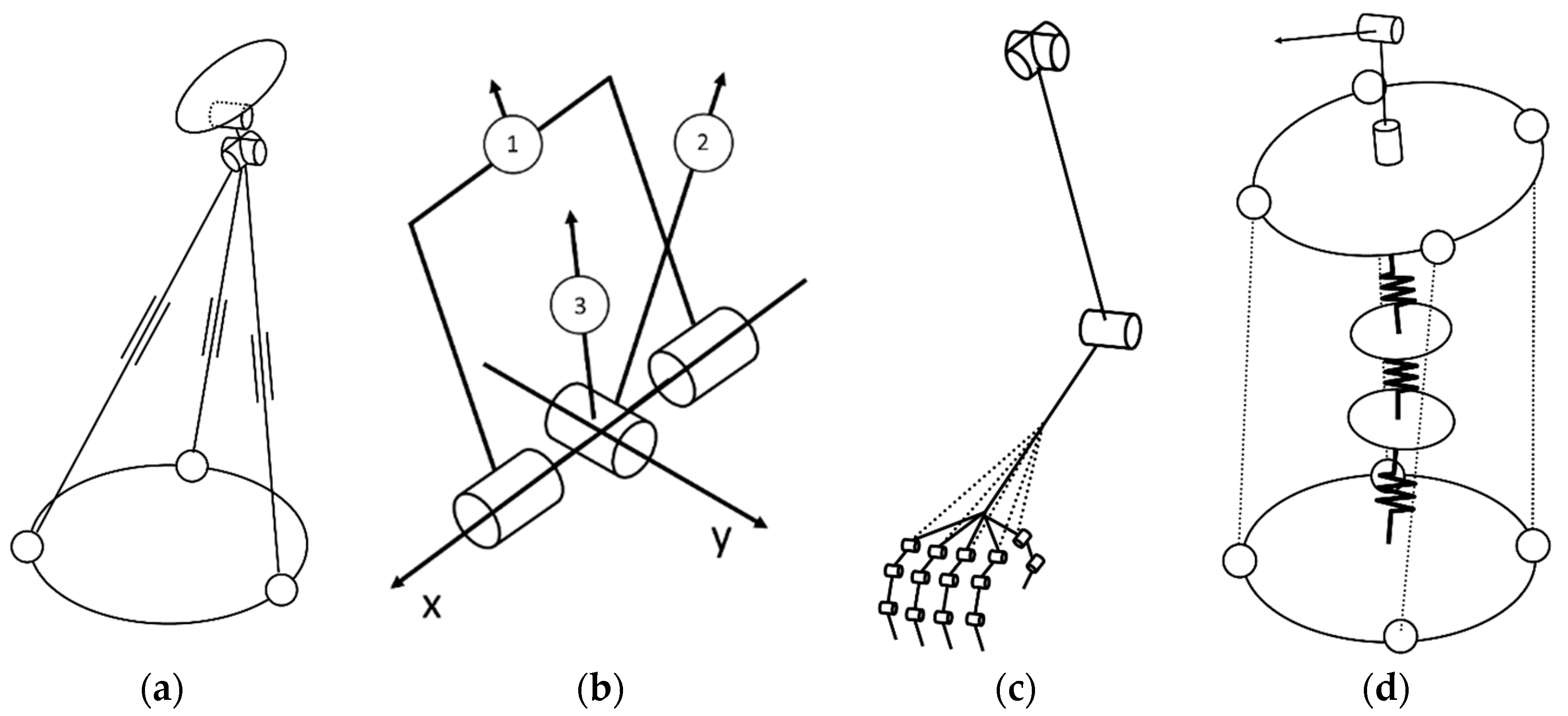
LARMbot 2 is characterized by three main mechanical subsystems, namely locomotion, manipulation, and torso. The locomotion subsystem is composed of two identical leg units. The kinematic scheme of the leg is shown in Figure 1a and its kinematics and dynamics are discussed and analyzed in detail in Reference [16,17]. Each leg unit is characterized by a hybrid structure with a 3UPR lower-mobility parallel mechanism that connects the hip to the ankle and that is actuated by three linear actuators in the links. An additional rotational motor is placed on the ankle for an additional degree of freedom of the foot platform, to achieve balance during walking operations by better reacting to disturbances on the frontal plane (XZ plane in Figure 2). Each leg unit has four degrees of freedom (three translational and a rotational one), for a total of eight degrees of freedom for the locomotion subsystem of the humanoid. With respect to the previous 3UPU leg design, the novel leg design is characterized by a larger workspace with no singular configurations, as detailed in Reference [16], owing to its special joint design. As shown in the kinematic scheme in Figure 1b, this joint design is characterized by three revolute joints around axes that converge at the center of the platform.
The manipulation subsystem is composed of two arm units, which are based on the kinematic scheme shown in Figure 1c. The upper arm is a 3R serial chain with two rotational degrees of freedom in the shoulder and an additional revolute joint in the elbow. The hand is a cable-driven mechanism, characterized by a 3R structure for each finger apart from the thumb, which is a 2R serial chain. Each revolute joint has a limited rotational motion of π/2 rad controlled by a small torsional spring placed between the consecutive phalanxes or palm and the first phalanx. The springs keep each finger open in a straight position, unless a cable that runs into it is pulled. Each finger is driven by a different cable, and all the cables are attached to a pulley driven by a servomotor located in the wrist. Thus, each arm unit is characterized by an underactuated mechanism with 17 rotational degrees of freedom (3 for the upper arm, and 14 for the hand), where the motion is regulated by 4 servomotors and 14 torsional springs.
The torso is based on the CAUTO design presented in Reference [13], which is a cable-driven, underactuated hybrid manipulator based on the kinematic scheme in Figure 1d. The lower part of the torso consists of an underactuated serial chain, composed of rigid bodies and elastic joints (E) with combined spherical and translational mobility alternating in a 3E chain. Four cables with varying length (assimilable to an SPS chain) are connected in parallel to the 3E chain to control the relative position of the upper torso platform with respect to the hip platform. The entire lower-torso architecture can be described as a 4SPS-(3E) parallel mechanism with 4 degrees of freedom, which are actuated by the four motors that regulate the length of each cable. The upper torso has two additional rotational degrees of freedom in the neck, for a total of 6 degrees of freedom. As outlined in Reference [18], the motion of the torso can be used to enhance and support walking balance. Therefore, CAUTO’s mobility compensates for the missing degrees of freedom in each leg, allowing the LARMbot 2 to achieve balance and react to disturbances parallel to the sagittal plane (YZ plane, with reference to Figure 2).
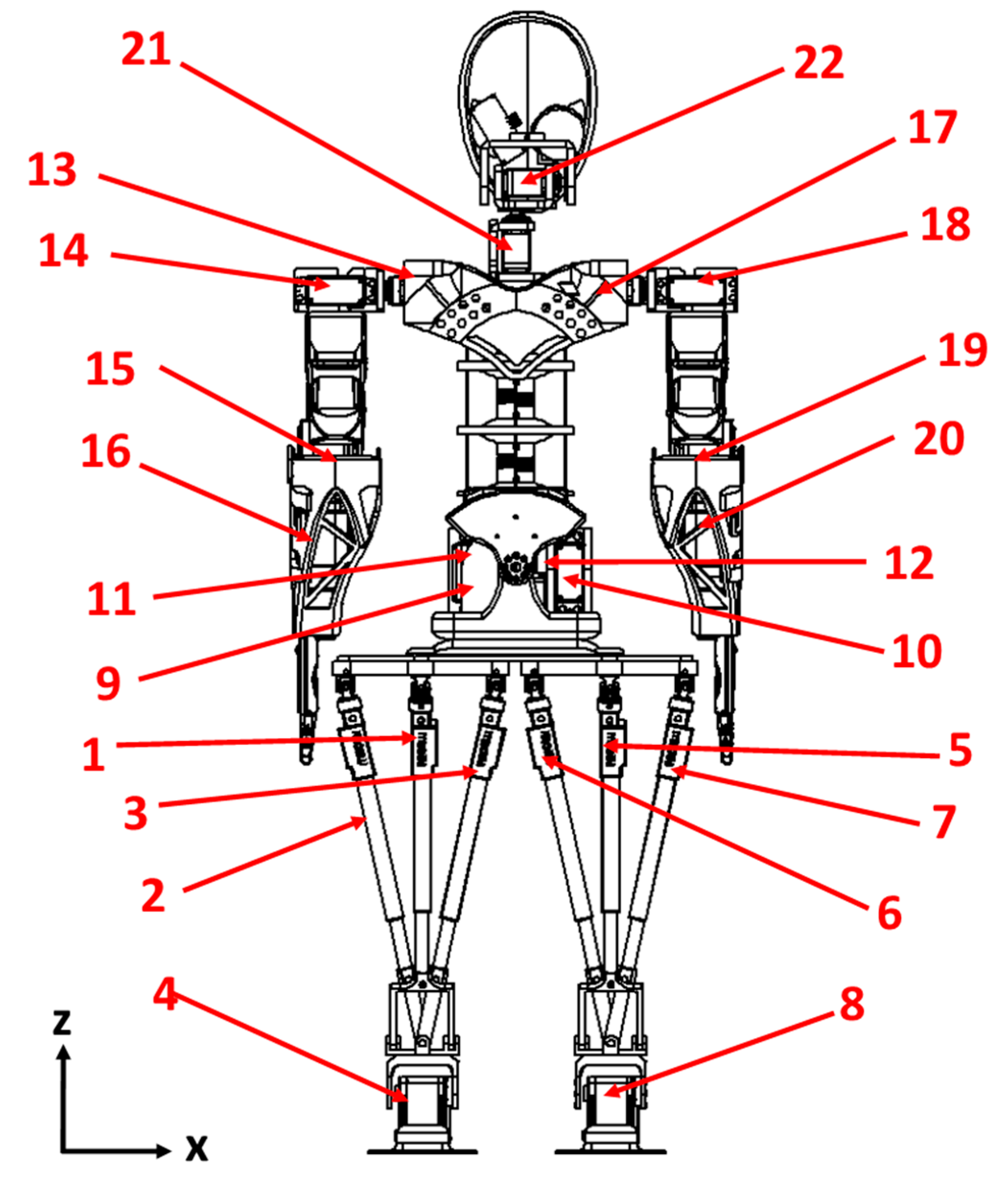
In Table 1, the main features of the LARMbot 2 are summarized. The entire humanoid is driven by 22 motors. Sixteen motors are rotational motors, while six are linear actuators. The position of the motors is shown in Figure 2, with additional details on the type and location of motors shown in Table 2.
3. Prototype Construction
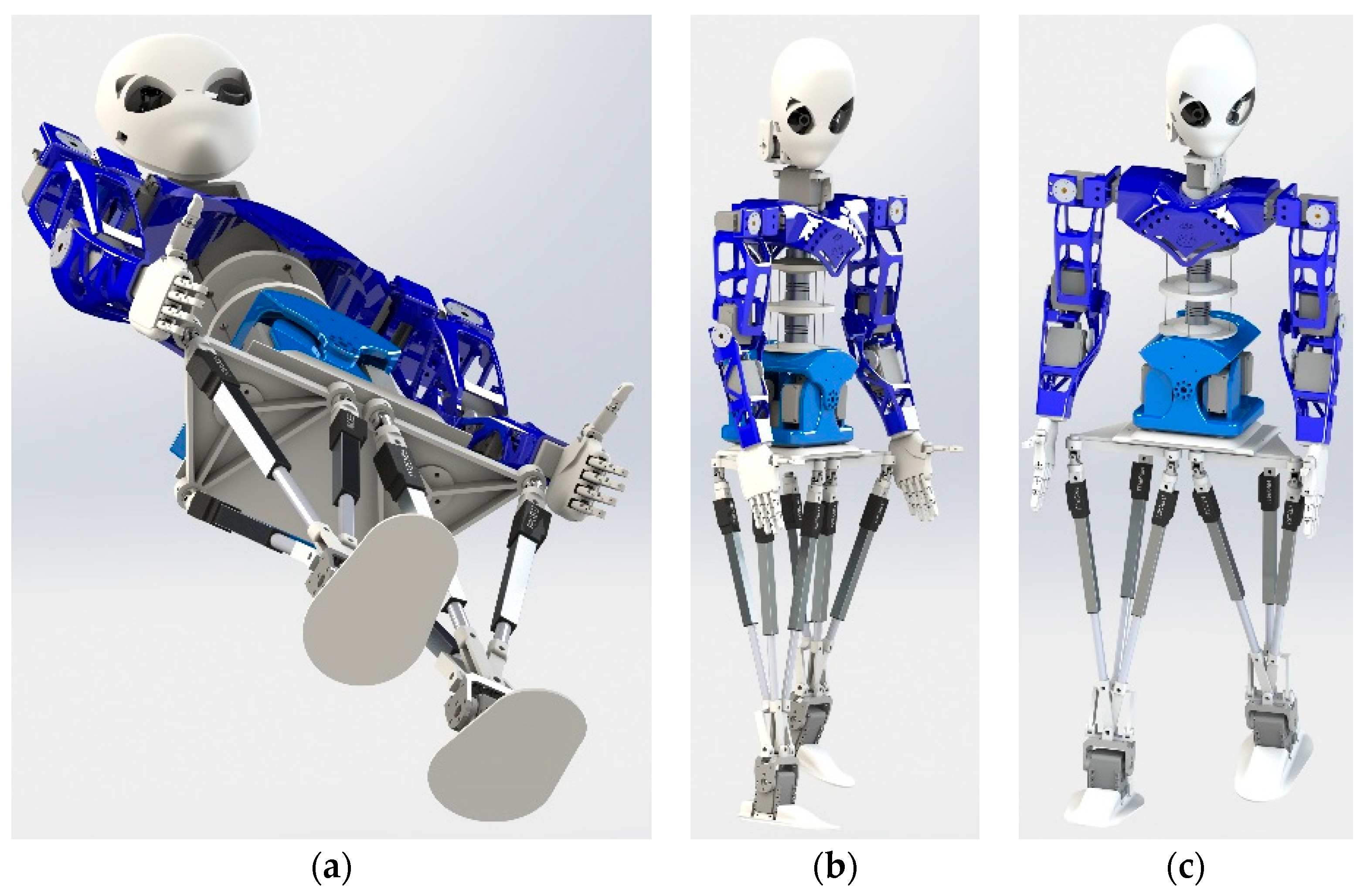
LARMbot 2 was conceived as a low-cost humanoid robot. Therefore, it was designed to be manufactured through 3D printing [19], controlled by commercial boards [20,21], and driven by commercial servomotors and linear actuators [22,23]. The cost of all the components for the final prototype was lower than 2000€. A CAD model of the humanoid robot can be seen in Figure 3, whilst a prototype is shown Figure 4.
The locomotion module of the prototype is less than 320 mm wide, 150 mm deep, and 400 mm high. Its weight is 1.05 kg, considering both the mechanical structure and electronics. The upper body (torso, head, and manipulation module) is 320 mm wide, 150 mm deep, and 450 mm high, and its weight is equal to 2.60 kg. Thus, the entire prototype is 850 mm tall and has a total weight of approximately 3.70 kg (approximately 2.00 kg for the motors and the 3D printed frame, and 1.70 kg for the control boards, sensors, and battery), making the entire system compact and lightweight. Its payload capability for manipulation is 0.85 kg, limited by the serial structure of the arm, whilst the parallel architecture of the torso and legs allows for a theoretical payload up to 3.00 kg. The payloads were evaluated for the peak efficiency point of the linear servomotors and at the estimated torque at operating speed for the rotational servomotors.
The hand of LARMbot 2 is one of the most challenging components to design and manufacture, with its five-finger cable-driven structure, as shown in the model in Figure 5. Its size is 24 × 110 × 90 mm. Each finger is actuated by a single cable, which runs through a ϕ2.83 mm guide running through the palm. The cables are characterized by a 0.23 mm diameter and are Dyneema cables in gel spun polyethylene, which is a synthetic fiber designed for traction strength. All the cables are attached to a single servomotor in the wrist, which controls the closure of the hand by pulling all the cables together. When the cables are released, the opening movement is performed by torsional springs that are enclosed within each finger and the palm, and within the consecutive phalanxes of the same finger. An exploded view of a single finger with the torsional springs is reported in Figure 6b. This mechanism design allows the hand to adapt to different shapes of grasped objects, while still being able to lift objects weighting up to 1.00 kg.
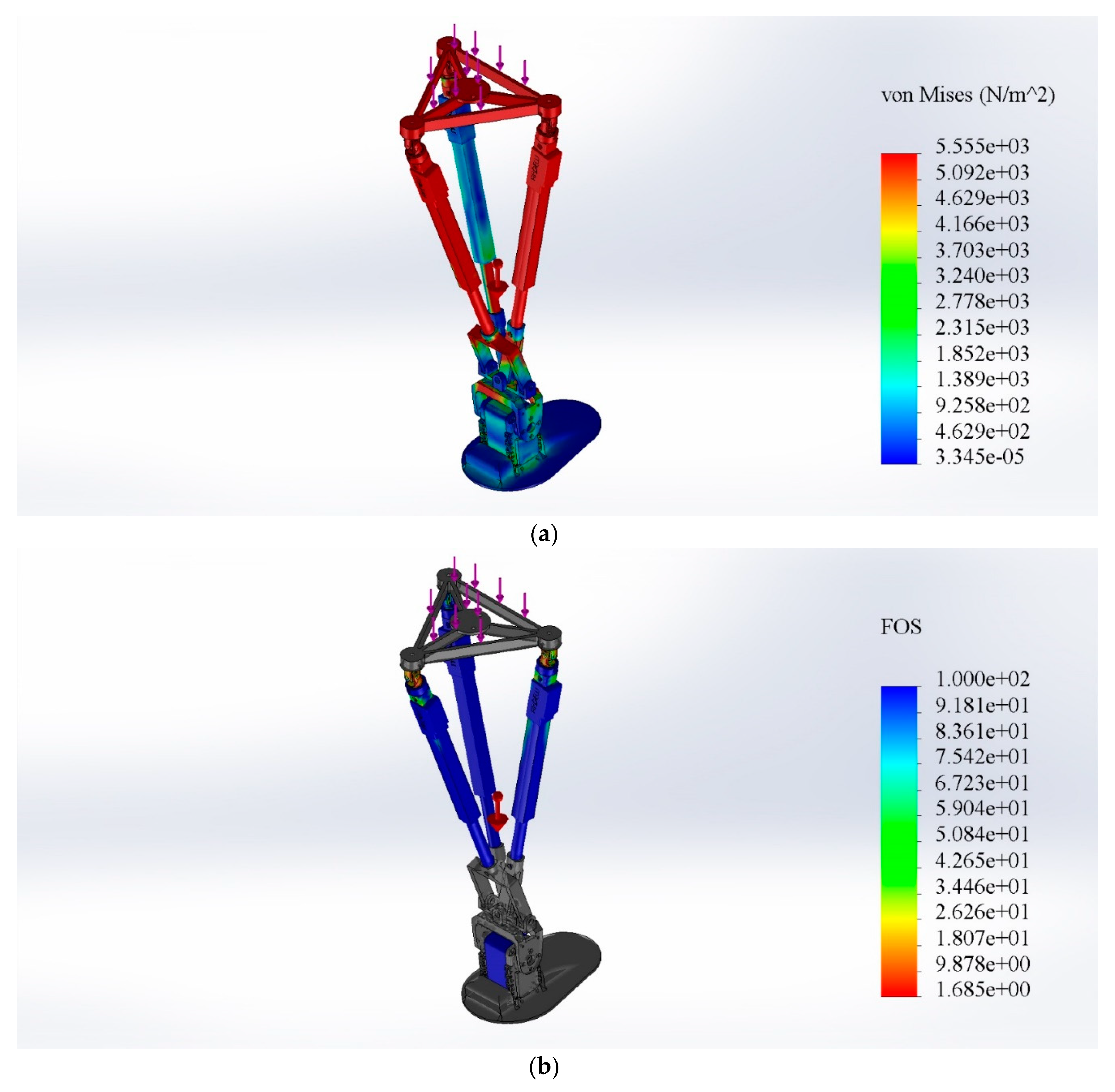
The prototype was validated with both dynamical simulations and Finite Element Analysis (FEA). A detailed characterization of the upper body was reported in Reference [13]. A dynamic simulation of a step was performed to identify the most critical load configurations on the leg. In those configurations, the proposed design was validated with a FEM analysis that was characterized by the load of the upper body with the maximum payload applied to the upper platform of a single leg. The FE simulation assumed all the 3D-printed components as ABS bodies with a linear elastic and isotropic behavior (tensile strength equal to 3 × 10⁷ N/m2), with a fixture constraint which locks the foot to the ground and a load equal to the weight of the upper body plus a 36 N external payload applied normally to the upper platform of the leg. The system was meshed with 4 Jacobian points, maximum element size of 6.67 mm and minimum element size of 0.33 mm. The results in Figure 6 highlight the capability of the proposed design to withstand the maximum load. In particular, Figure 6a shows the load distribution on the leg structure, with a maximum stress of 5.55 × 10³ N/m2, and Figure 6b reports the corresponding factor of safety (FOS) on the commercial components. The critical component was the nut of the universal joint, which still showed a FOS of 1.7 in the most critical load configuration, whilst the actuators and the 3D printed components could easily withstand the stress.
4. Control and Sensing
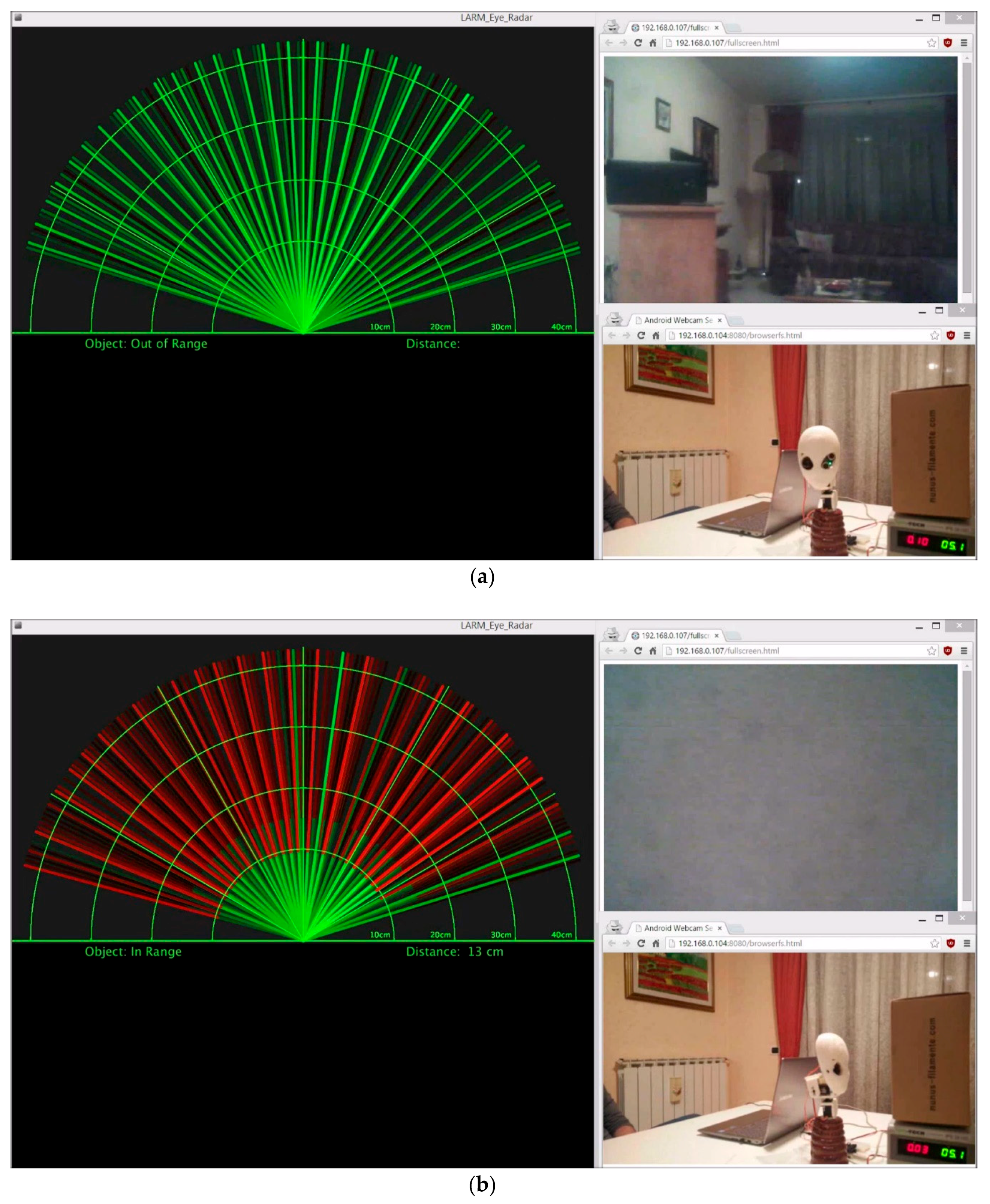
LARMbot 2 is equipped with several onboard sensors, which range from Inertial Measurement Units (IMUs) to current sensors and cameras. In particular, its head is equipped with an Inertial Measurement Unit (IMU) that is encased in the back of the neck. The right eye is a Wi-Fi mini-camera that can acquire and record audio and video, with a resolution of 640 × 480 px at 30 fps. Its view angle is equal to 60°, and it can transmit information up to 15 m. The left eye stores an ultrasonic distance sensor that is able to detect the distance of the closest object in front of it from 20 mm up to 3 m. An example of the head sensors in function is reported in Figure 7. The figure shows the data acquired by the sensors through a software interface from a computer, where it is possible to see the signal that is acquired from the ultrasonic distance sensor on the left side. The upper window on the right is the real-time acquisition from the Wi-Fi mini-camera of the right eye, while the lower window on the right is an external camera that shows the head with the surrounding environment. In Figure 7a the head is facing the empty room, and no obstacle is detected by the ultrasonic distance sensor. In Figure 7b, the head is facing a cardboard box instead, and the distance sensor detects the obstacle at a distance of 130 mm, as reported by the interface, which also gives a graphical representation of the field of view (green lines are open field of view, red lines are no field of view).
The control system of the novel locomotion module was based on Arduino boards [20], with a single Arduino Nano board with a PID control for both legs, passing through an Adafruit PWM Servo Driver board [21] to control the servomotors [22,23] with a velocity-based PID controller. An Inertial Measuring Unit (IMU) [24] was placed on the moving platform of the parallel mechanism for each leg to measure the angular displacement and linear acceleration of the prototype. A current sensor was used to measure the power consumption, since the power supply was set to a constant 6.8 V voltage. Another Arduino Nano board controls all the sensors. A computer was used both as remote the control for the locomotor and to acquire and store the data from the sensors. The control system is summarized by the conceptual scheme in Figure 8, and motion control was based on the closed-form expression of kinematics as presented in Reference [16].
5. Experimental Validation
To characterize the step size, walking, and weight lifting performance of the novel locomotion module, two different experiments were performed: the first one was a constrained walking operation of the locomotion module, whilst the second one was a weight-lifting operation of the entire humanoid. The walking operation was characterized by a rectangular step of length equal to 200 mm and a height equal to 30 mm. The walking step trajectory was optimized by using the Output Transmission Index as the criterion [16]. The Transmission Index is a virtual coefficient that represents the virtual power delivered by a unit transmission wrench on the corresponding unit output twist of the target body. Thus, it characterizes the force transmission performance of a robot. The chosen trajectory was contained in a region of the workspace with an Output Transmission Index greater than 0.55. The input of the linear actuators for the chosen path were calculated through Inverse Kinematics and are shown in Figure 9a. In Figure 9b eight different snapshots of the test are shown as starting position, left pre-swing, left swing, double support with left forward, right mid-swing, right swing, double support with right forward, and left mid-swing, respectively. Owing to the leg design, the steps are wide even for a short motion of the sliding actuated links.
The accelerometers and gyroscopes of the IMUs were used to measure both the angular displacement and the linear acceleration of the feet of the prototype. Since during the walking operation the path of the right leg is equal to the one of the left leg but with a different phase, it is possible to use the results of a single leg to characterize the motion. Several tests consisting of five steps each were performed, with similar results. The results shown in this paper refer only to step 3 and 4 as characteristic behavior, since all the other steps showed some transitory effect for the beginning and the end of the operation.
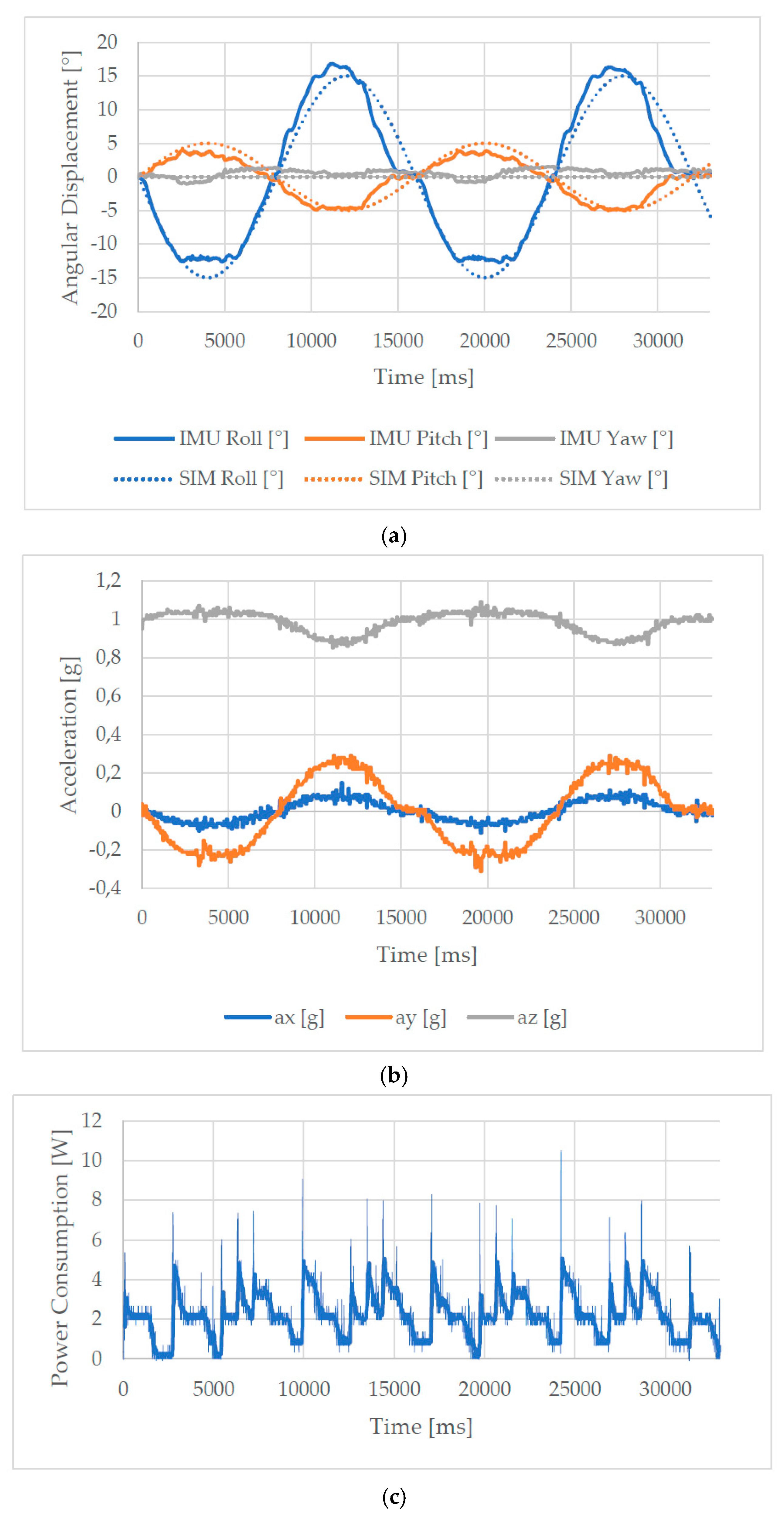
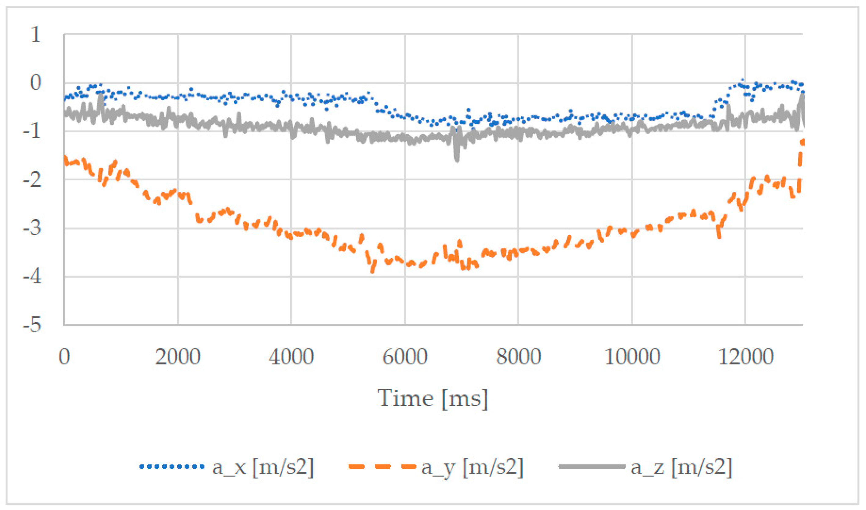
In Figure 10a, the results for the angular displacement of the foot during the step operation are shown. The measurements obtained with the IMU could be successfully compared with the expected angular displacement evaluated through a kinematic analysis and shown in Figure 10a in the form of a dotted line. A further characterization of the step operation could be obtained from the linear acceleration data acquired by the IMU, as reported in Figure 10b.
The acceleration was normalized to the standard acceleration due to gravity g (9.80665 m∙s−2), where the effect could be observed even on the value of the linear acceleration along the Z-axis, that was oscillating around 1g instead of 0. The graph in Figure 10b shows that there were no sudden changes in the motion and that the entire walking operation was fairly smooth, with a maximum acceleration of 0.2 g, thanks to the stiff operation of the parallel architecture of the leg design.
The power consumption of the locomotion system was obtained by multiplying the current measured by the current sensor and the voltage, fixed to 6.8 V by the power supply. The acquired data are shown in Figure 10c. The peak value of power consumption was lower than 11.000 W, whilst the power RMS (root mean square) was 2.536 W. Therefore, the system could be powered by a Li-Po battery, making the robot able to operate completely through Bluetooth or wireless technologies. The estimated specific cost of transport [25] of the prototype, which was defined as cet = (energy used)/(weight)(distance traveled), was 2.5, which was comparable to the values for other biped robots as reported in Reference [25].
To prove the payload capability of the LARMbot 2 prototype, experimental load-lifting tests were carried out. The experiments are characterized by a lifting motion of LARMbot 2 while subject to its own weight, and an additional weight of 1.00 kg was applied to the back of the humanoid. Table 3 reports the main parameters for the two experimental modes. For both test modes, an IMU sensor in the neck of the prototypes measured angular displacement and linear acceleration. A current sensor was used to get the power, since the entire system was powered by a 12 V supply.
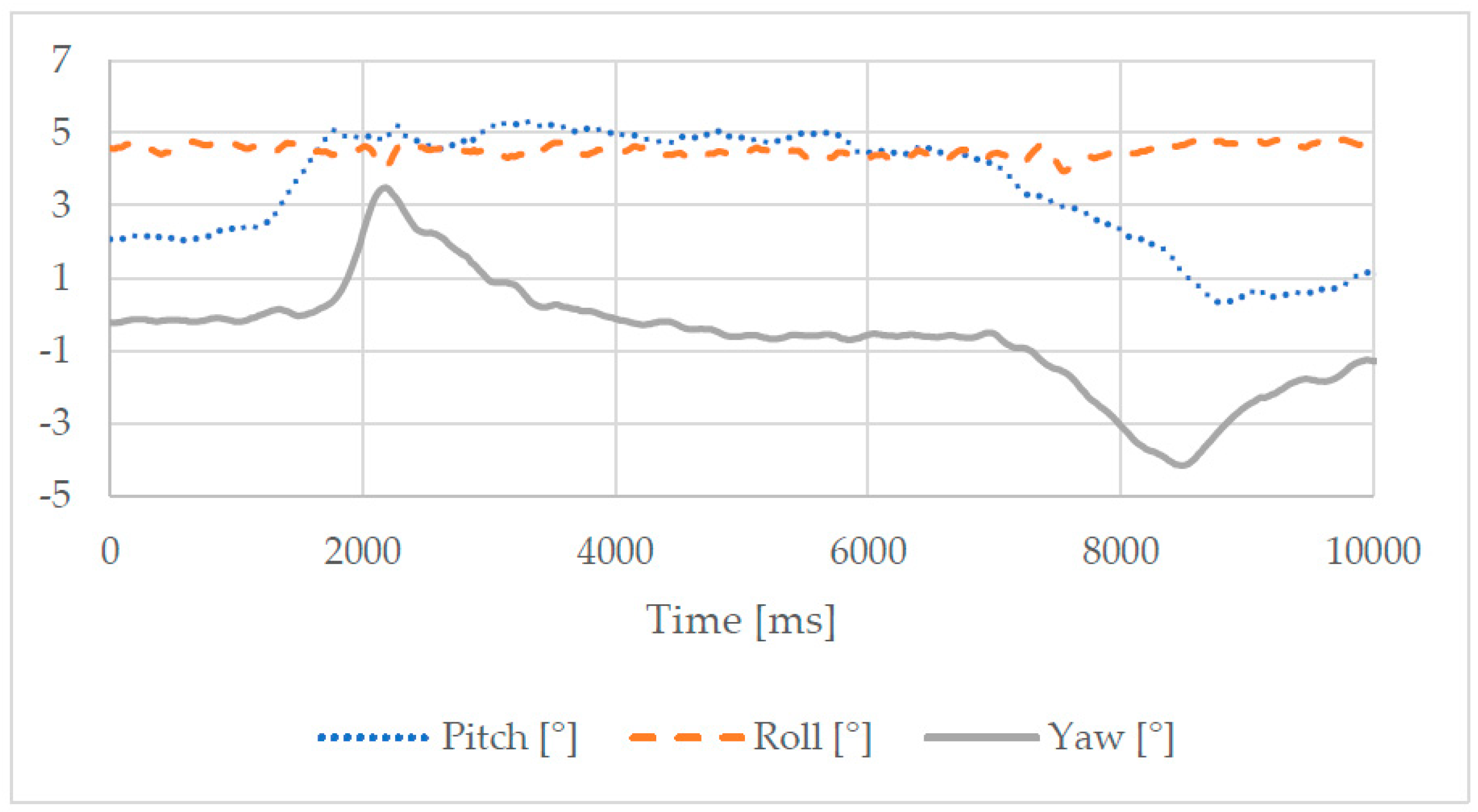
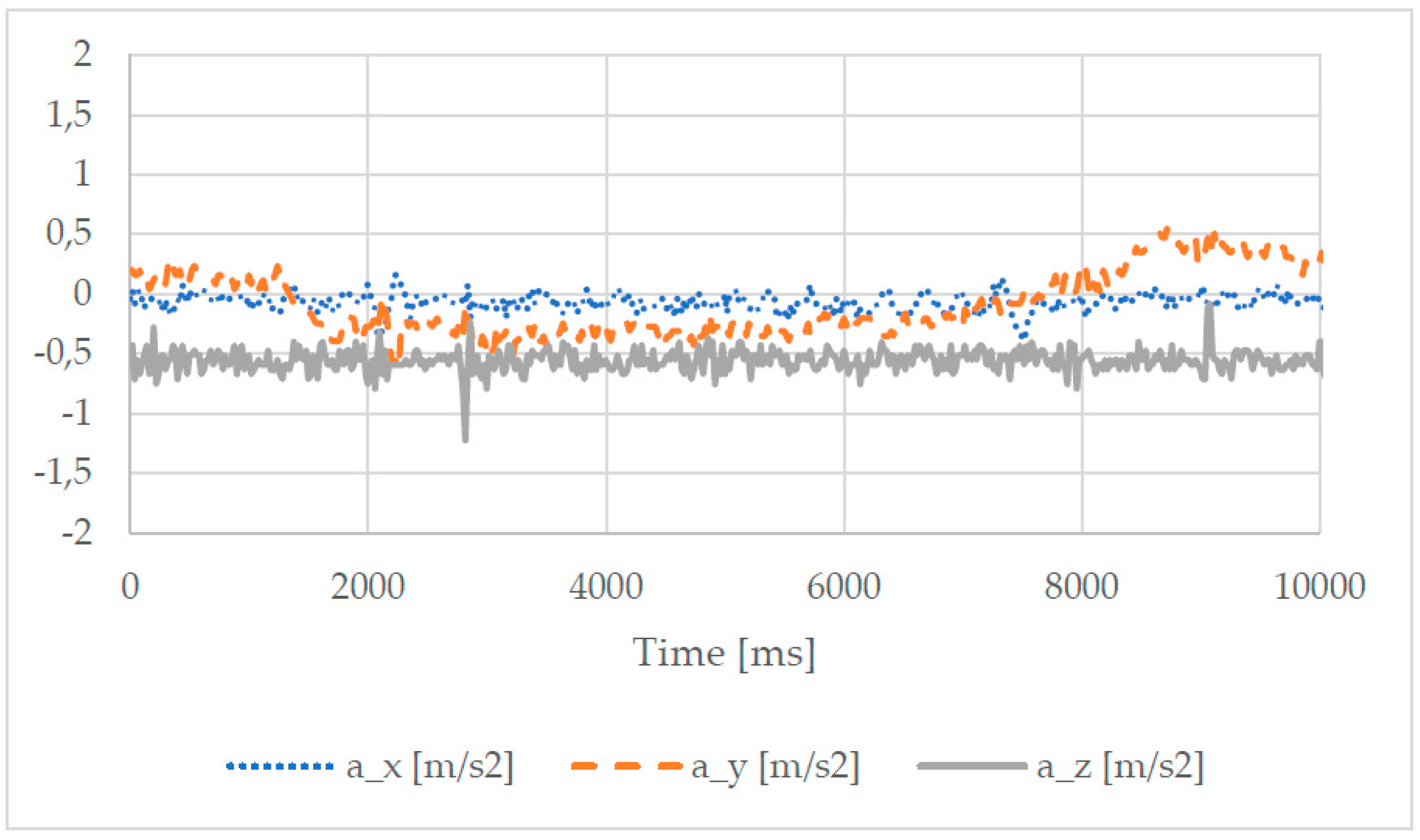
The first test mode was characterized by a lifting movement along the vertical axis equal to 80 mm. There was no payload applied to the structure apart from its own weight. The results for the first test mode are shown in Figure 11 and Figure 12. The plots in Figure 11 showed that the torso tilted slightly forward during the lifting phase (pitch angle varying by approximately 4°), whilst there was a transient change of facing at the beginning and at the end of the lifting phase (yaw angle varying). The angular motion was extremely limited, with a maximum variation of 5°. The motion was performed in a smooth, continuous motion, as shown by the small variation in the linear acceleration in Figure 12. The peak of power consumption in this test was approximately 20.00 W.
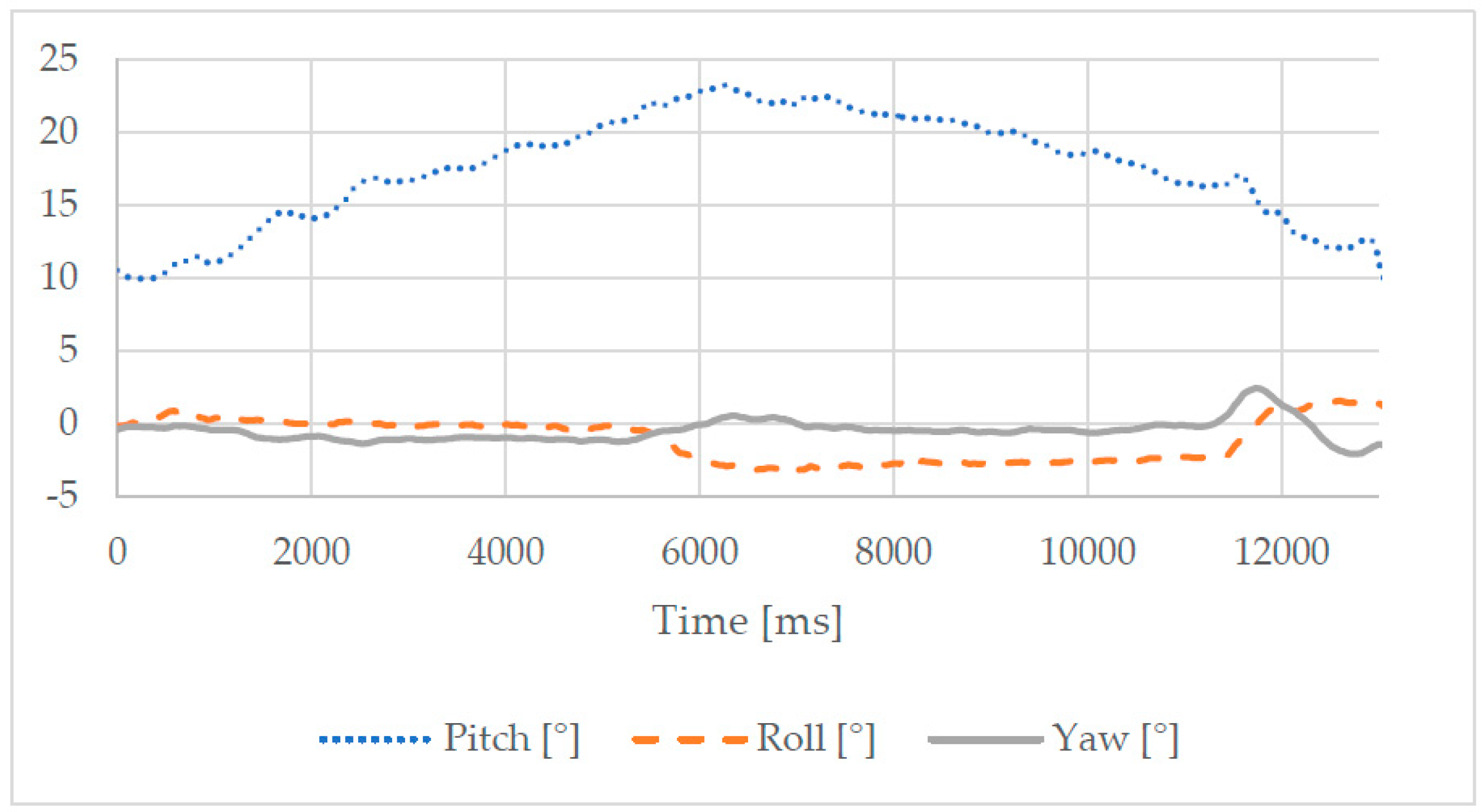
The second test mode was characterized by the same lifting movement along the vertical axis. There was a payload of 1.00 kg applied to the back of the torso. The results for this test mode are shown in Figure 13 and Figure 14. The plots in Figure 13 show that the torso tilts forward during the lifting phase (pitch angle varying of approximately 15°), while the variation of the other angles is less significant. The angular motion was extremely limited, with a maximum variation of 5°. The motion was performed in a smooth, continuous motion, as shown by the small variation in the linear acceleration in Figure 14. The peak of power consumption in this test was approximately 25.00 W.
When compared to the results of the previous test mode, the torso was tilted forward by 10° for the beginning to balance the weight on its back, and a bigger displacement on the pitch angle was needed to keep balance during motion. The acceleration plots of the second mode showed more disturbances than the first one, but the plots variation was contained within 2 m/s2. Overall, the experimental tests validated the payload capability of the proposed structure.
In conclusion, the experimental tests validated the expected performance of the LARMbot 2. The locomotion module could perform walking operations with a step size that was large when compared to other existing legs with parallel architecture, owing to the special joint mechanism first introduced in Reference [26]. Furthermore, the parallel architectures of the leg and torso allowed LARMbot 2 to lift a considerable weight. The power consumption of the whole humanoid was lower than 20 W for all the experimental tests.
6. Conclusions
A novel humanoid robot, the LARMbot 2, was introduced in this paper as a lightweight, low-cost solution based on parallel architectures for the torso and leg mechanisms. The kinematics of the whole humanoid was described, and a CAD model was presented for a constructive solution that was validated with a prototype. The parallel architectures on which the robot is based allowed it to lift a considerable payload, especially when compared to the weight of the entire system, as proven by the experimental data. Furthermore, the performance of the novel leg design was evaluated during a walking operation by both numerical computation and experimental tests. The results showed that the proposed leg mechanism could perform the walking task with good efficiency and low power consumption, with an improved performance compared to the previous LARMbot design. A full dynamic control that coordinates the legs, torso, and arms for dynamic walking and manipulation will be developed in future works.
7. Patents
Russo M., Cafolla D., Ceccarelli M., “Dispositivo per gamba tripode (Device for tripod leg)”, IT patent application 102016000097258, 28/09/2016.
Russo M., Ceccarelli M., “Dispositivo di collegamento sferico tra tre corpi (Device for the spherical connection of three bodies)”, IT patent application 102016000093695, 19/09/2016.
Author Contributions
Conceptualization, M.R. and M.C.; Data curation, M.R. and D.C.; Formal analysis, M.R.; Funding acquisition, M.C.; Investigation, M.R. and D.C.; Methodology, M.C.; Project administration, M.C.; Software, M.R. and D.C.; Supervision, M.C.; Validation, M.R. and D.C.; Writing—original draft, M.R.; Writing—review & editing, M.R. and M.C.
Funding
This research received no external funding.
Conflicts of Interest
The authors declare no conflict of interest.
References
- Lim, H.O.; Takanishi, A. Biped walking robots created at Waseda University: WL and WABIAN family. Philos. Trans. R. Soc. Lond. A 2007, 365, 49–64. [Google Scholar] [CrossRef] [PubMed] [Green Version]
- Kulk, J.; Welsh, J. A low power walk for the NAO robot. In Proceedings of the 2008 Australasian Conference on Robotics & Automation (ACRA-2008), Canberra, Australia, 3–5 December 2008; Kim, J., Mahony, R., Eds.; pp. 1–7. [Google Scholar]
- Metta, G.; Natale, L.; Nori, F.; Sandini, G.; Vernon, D.; Fadiga, L.; Bernardino, A. The iCub humanoid robot: An open-systems platform for research in cognitive development. Neural Netw. 2010, 23, 1125–1134. [Google Scholar] [CrossRef] [PubMed]
- Tsagarakis, N.G.; Caldwell, D.G.; Negrello, F.; Choi, W.; Baccelliere, L.; Loc, V.G.; Natale, L. WALK-MAN: A High-Performance Humanoid Platform for Realistic Environments. J. Field Robot. 2017, 34, 1225–1259. [Google Scholar] [CrossRef]
- Lafaye, J.; Gouaillier, D.; Wieber, P.B. Linear model predictive control of the locomotion of Pepper, a humanoid robot with omnidirectional wheels. In Proceedings of the IEEE 2014 14th IEEE-RAS International Conference on Humanoid Robots, Madrid, Spain, 18–20 November 2014; pp. 336–341. [Google Scholar]
- Ogura, Y.; Aikawa, H.; Shimomura, K.; Morishima, A.; Lim, H.O.; Takanishi, A. Development of a new humanoid robot WABIAN-2. In Proceedings of the IEEE International Conference on Robotics and Automation, Orlando, FL, USA, 15–19 May 2006; pp. 76–81. [Google Scholar]
- Jung, H.W.; Seo, Y.H.; Ryoo, M.S.; Yang, H.S. Affective communication system with multimodality for a humanoid robot, AMI. In Proceedings of the 2004 4th IEEE/RAS International Conference on Humanoid Robots, Santa Monica, CA, USA, 10–12 November 2004; Volume 2, pp. 690–706. [Google Scholar]
- Tellez, R.; Ferro, F.; Garcia, S.; Gomez, E.; Jorge, E.; Mora, D.; Pinyol, D.; Oliver, J.; Torres, O.; Velazquez, J.; et al. Reem-B: An autonomous lightweight human-size humanoid robot. In Proceedings of the IEEE 8th IEEE-RAS International Conference on Humanoid Robots, Daejeon, Korea, 1–3 December 2008; pp. 462–468. [Google Scholar]
- Asfour, T.; Regenstein, K.; Azad, P.; Schroder, J.; Bierbaum, A.; Vahrenkamp, N.; Dillmann, R. ARMAR-III: An integrated humanoid platform for sensory-motor control. In Proceedings of the 6th IEEE-RAS International Conference on Humanoid Robots, Genova, Italy, 4–6 December 2006; pp. 169–175. [Google Scholar]
- Asfour, T.; Schill, J.; Peters, H.; Klas, C.; Bücker, J.; Sander, C.; Bartenbach, V. Armar-4: A 63 DOF torque controlled humanoid robot. In Proceedings of the 13th IEEE-RAS International Conference on Humanoid Robots (Humanoids), Atlanta, GA, USA, 15–17 October 2013; pp. 390–396. [Google Scholar]
- Cafolla, D.; Wang, M.F.; Carbone, G.; Ceccarelli, M. LARMbot: A new humanoid robot with parallel mechanisms. In Romansy 21—Robot Design, Dynamics and Control: Proceedings of the 21st Cism-Iftomm Symposium, June 20–23, Udine, Italy; Springer International Publishing: Cham, Switzerland, 2016; pp. 275–284. [Google Scholar]
- Ceccarelli, M.; Cafolla, D.; Russo, M.; Carbone, G. LARMBot Humanoid Design towards a Prototype. MOJ Appl. Bionics Biomech. 2017, 1, 48–49. [Google Scholar] [CrossRef]
- Cafolla, D.; Ceccarelli, M. Design and simulation of a cable-driven vertebra-based humanoid torso. Int. J. Humanoid Robot. 2016, 13, 1650015-1–1650015-27. [Google Scholar] [CrossRef]
- Cafolla, D.; Ceccarelli, M. An Experimental Validation of a Novel Humanoid Torso. Robot. Auton. Syst. 2017. [Google Scholar] [CrossRef]
- Wang, M.; Ceccarelli, M. Design and simulation of walking operation of a cassino biped locomotor. In New Trends in Mechanism and Machine Science; Springer International Publishing: Cham, Switzerland, 2015; pp. 613–621. [Google Scholar]
- Russo, M.; Ceccarelli, M.; Takeda, Y. Force transmission and constraint analysis of a 3-SPR parallel manipulator. Proc. Inst. Mech. Eng. Part C J. Mech. Eng. Sci. 2017. [Google Scholar] [CrossRef]
- Russo, M.; Herrero, S.; Altuzarra, O.; Ceccarelli, M. Kinematic Analysis and multi-objective optimization of a 3-UPR parallel mechanism for a robotic leg. Mech. Mach. Theory 2018, 120, 192–202. [Google Scholar] [CrossRef]
- Cafolla, D.; Chen, I.M.; Ceccarelli, M. An experimental characterization of human torso motion. Front. Mech. Eng. 2015, 10, 311–325. [Google Scholar] [CrossRef]
- Ceccarelli, M.; Carbone, G.; Cafolla, D.; Wang, M. How to Use 3D Printing for Feasibility Check of Mechanism Design. In Advances in Robot Design and Intelligent Control; Borangiu, T., Ed.; Advances in Intelligent Systems and Computing; Springer: Cham, Switzerland, 2016; Volume 371. [Google Scholar]
- Arduino Nano Datasheet. Available online: https://store.arduino.cc/arduino-nano (accessed on 16 November 2018).
- Adafruit PWM Servo Driver Datasheet. Available online: https://www.adafruit.com/product/815 (accessed on 16 November 2018).
- Actuonix L12R Linear Servomotor Datasheet. Available online: https://www.actuonix.com/L12-R-Linear-Servo-For-Radio-Control-p/l12-r.htm (accessed on 16 November 2018).
- MG 995 Servomotor Datasheet. Available online: https://www.towerpro.com.tw/product/mg995/ (accessed on 16 November 2018).
- Adafruit IMU Datasheet. Available online: https://www.adafruit.com/product/3463 (accessed on 16 November 2018).
- Collins, S.H.; Ruina, A. A bipedal walking robot with efficient and human-like gait. In Proceedings of the 2005 IEEE International Conference on Robotics and Automation, Barcelona, Spain, 18–22 April 2005. [Google Scholar]
- Russo, M.; Ceccarelli, M. Kinematic design of a tripod parallel mechanism for robotic legs. In Mechanisms, Transmissions and Applications; Mechanism and Machine Science; Springer: Cham, Switzerland, 2018; Volume 52, pp. 121–130. [Google Scholar]
Figure 1.
Kinematic scheme of LARMbot 2: (a) Leg; (b) Leg 3R joint design; (c) Arm; (d) Torso.

Figure 2.
Actuators of LARMbot 2.

Figure 3.
CAD model of LARMbot 2: (a) Lower view; (b) Side view; (c) Front view.

Figure 4.
Prototype of LARMbot 2: (a) Torso and arms; (b) Legs; (c) Full assembly.
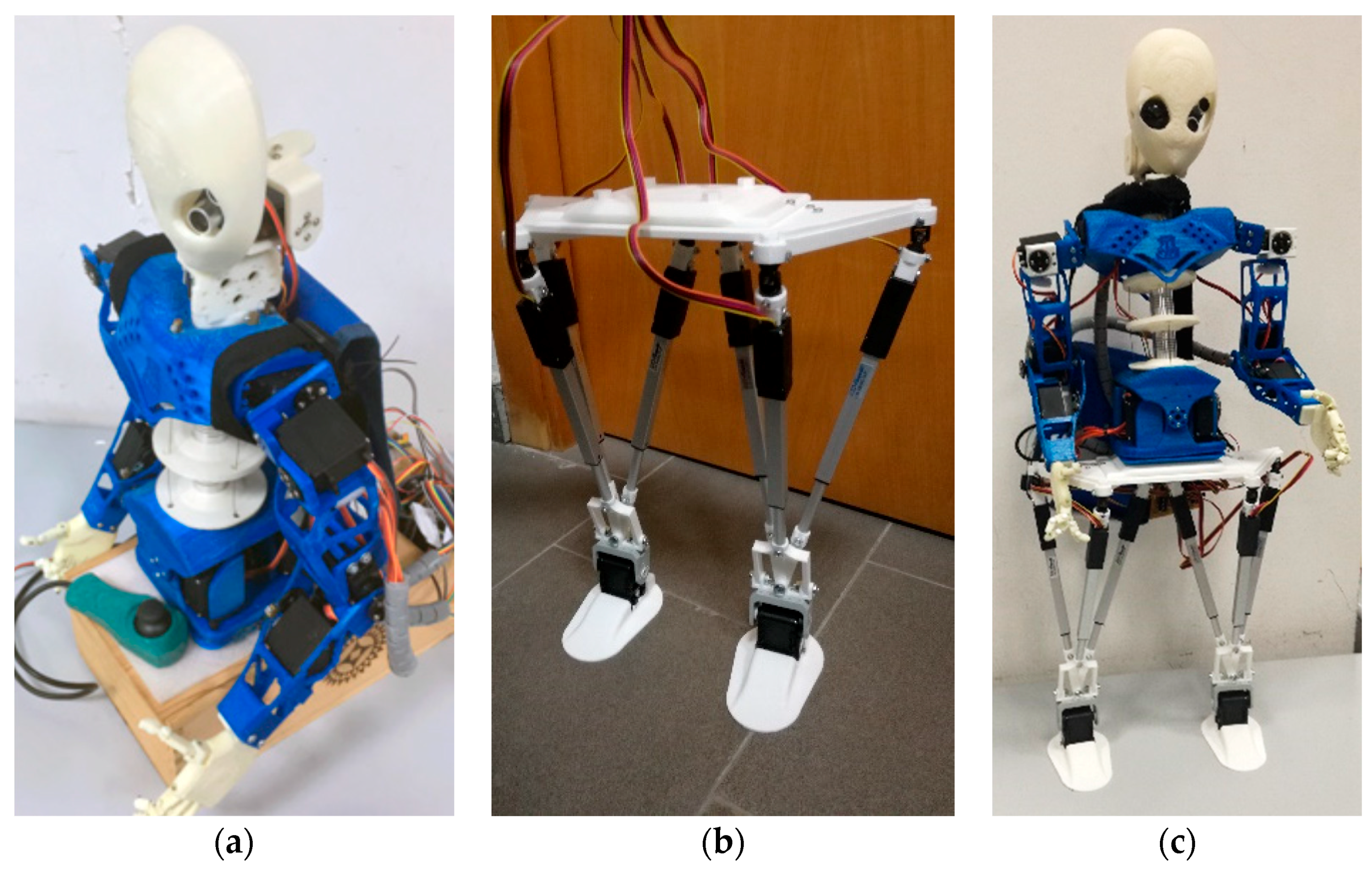
Figure 5.
LARMbot 2 hand design: (a) Hand model; (b) Exploded view of a finger.
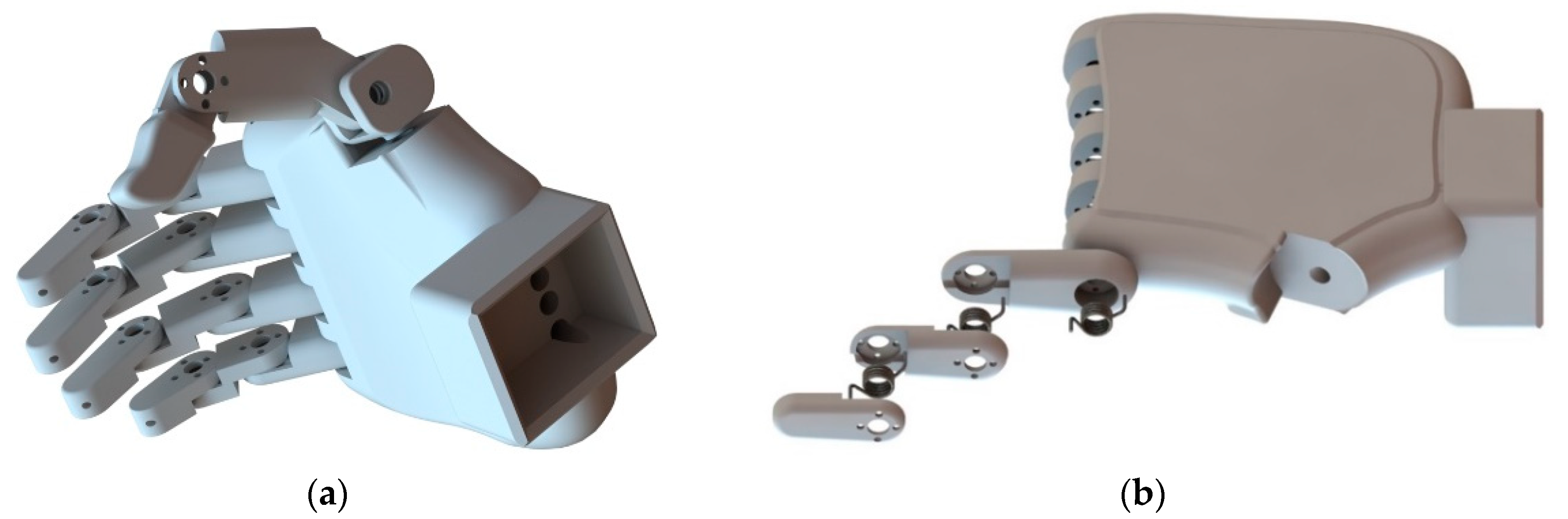
Figure 6.
Leg FEA: (a) Von Mises equivalent stress; (b) Factor of Safety distribution.

Figure 7.
Test of the head sensors: (a) No obstacle in range; (b) Obstacle in range.

Figure 8.
A conceptual scheme for the control of the biped locomotor module.

Figure 9.
Walking test: (a) Input of the linear servomotors (s2 and s3 overlap); (b) Snapshots.
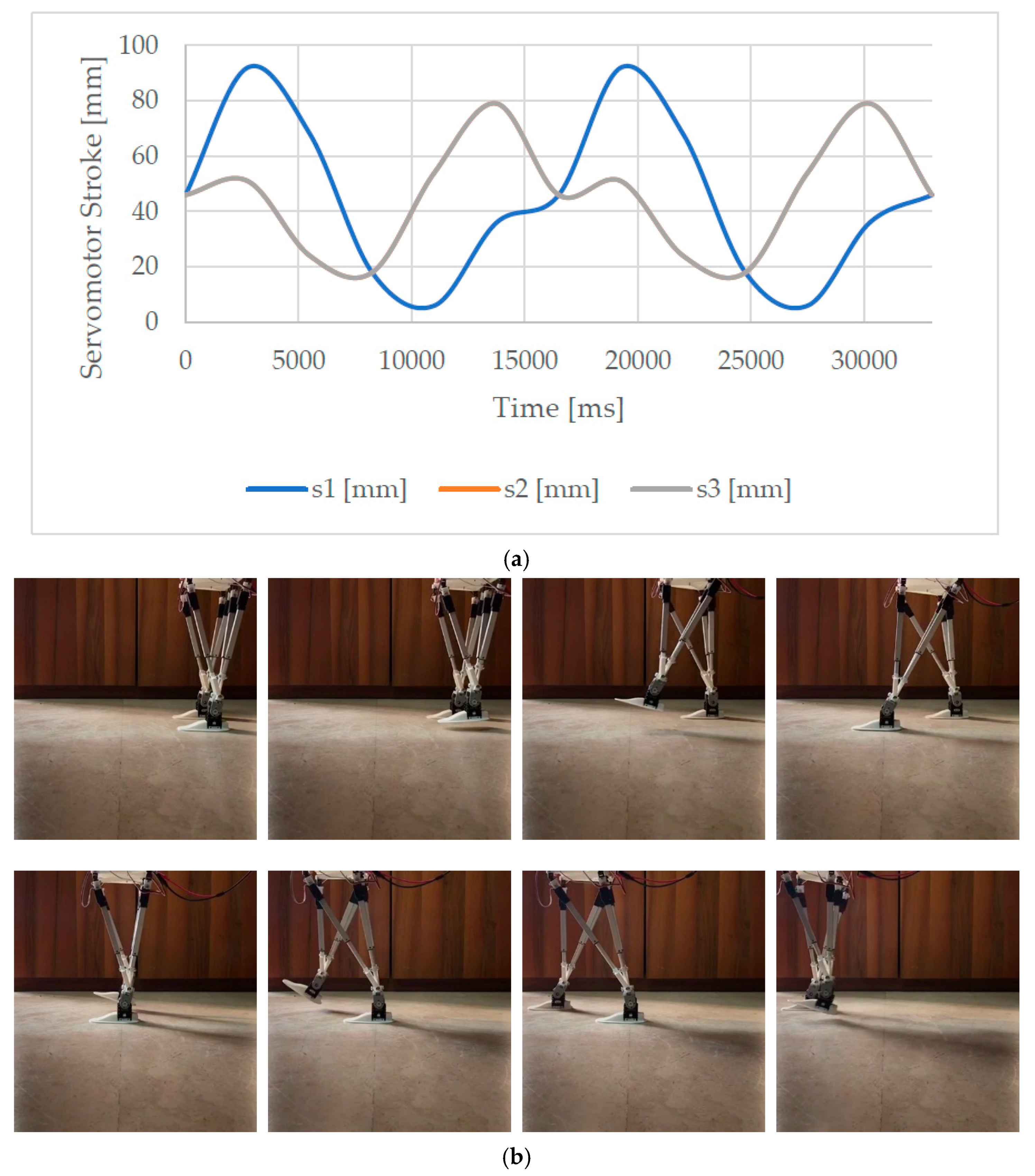
Figure 10.
Results of a walking test: (a) angular displacement of the foot; (b) Accelerations measured by the IMU on the foot; (c) Acquired power consumption.
Figure 10.
Results of a walking test: (a) angular displacement of the foot; (b) Accelerations measured by the IMU on the foot; (c) Acquired power consumption.

Figure 11.
Acquired angular displacement for test mode 1 without payload.

Figure 12.
Acquired linear acceleration for test mode 1 without payload.

Figure 13.
Acquired angular displacement for test mode 2 with payload.

Figure 14.
Acquired linear acceleration for test mode 2 with payload.


Table 1.
Modules of LARMbot 2.
| Module | Abbr. | W (mm) | D (mm) | H (mm) | Mass (kg) | Actuators |
|---|---|---|---|---|---|---|
| Left Leg | LL | 160 | 150 | 400 | 0.5 | 3 leg, 1 ankle |
| Right Leg | RL | 160 | 150 | 400 | 0.5 | 3 leg, 1 ankle |
| Torso | TO | 200 | 150 | 300 | 1.2 | 4 cables |
| Left Arm | LA | 60 | 60 | 360 | 0.5 | 3 arm, 1 hand |
| Right Arm | RA | 60 | 60 | 360 | 0.5 | 3 arm, 1 hand |
| Head | HD | 95 | 150 | 150 | 0.4 | 2 neck |
| LARMbot | - | 320 | 150 | 850 | 3.6 | 22 |
Table 2.
Degrees of Freedom of LARMbot 2 as in Figure 2.
Table 2.
Degrees of Freedom of LARMbot 2 as in Figure 2.
| DoF | Location | Description | Force/Torque | DoF | Location | Description | Force/Torque |
|---|---|---|---|---|---|---|---|
| q1 | LL | Linear actuator B | 36 N (4.5 mm/s) | q12 | TO | Cable servomotor FR | 1.08 Nm |
| q2 | LL | Linear actuator L | 36 N (4.5 mm/s) | q13 | LA | Shoulder motor 1 | 1.08 Nm |
| q3 | LL | Linear actuator R | 36 N (4.5 mm/s) | q14 | LA | Shoulder motor 2 | 1.08 Nm |
| q4 | LL | Ankle servomotor | 1.08 Nm | q15 | LA | Elbow motor | 1.08 Nm |
| q5 | RL | Linear actuator B | 36N (4.5 mm/s) | q16 | LA | Hand motor | 1.08 Nm |
| q6 | RL | Linear actuator L | 36N (4.5 mm/s) | q17 | RA | Shoulder motor 1 | 1.08 Nm |
| q7 | RL | Linear actuator R | 36N (4.5 mm/s) | q18 | RA | Shoulder motor 2 | 1.08 Nm |
| q8 | RL | Ankle servomotor | 1.08 Nm | q19 | RA | Elbow motor | 1.08 Nm |
| q9 | TO | Cable servomotor BL | 1.08 Nm | q20 | RA | Hand motor | 1.08 Nm |
| q10 | TO | Cable servomotor BR | 1.08 Nm | q21 | HE | Neck motor 1 | 1.08 Nm |
| q11 | TO | Cable servomotor FL | 1.08 Nm | q22 | HE | Neck motor 2 | 1.08 Nm |
Table 3.
Experimental test modes.
| Test Mode | Payload | Appl. Point | Moving Parts | Sensors |
|---|---|---|---|---|
| 1 | 0.00 kg | - | Legs, Torso | IMU, Current Sensor |
| 2 | 1.00 kg | Back | Legs, Torso | IMU, Current Sensor |
© 2018 by the authors. Licensee MDPI, Basel, Switzerland. This article is an open access article distributed under the terms and conditions of the Creative Commons Attribution (CC BY) license (http://creativecommons.org/licenses/by/4.0/).
Share and Cite
MDPI and ACS Style
Russo, M.; Cafolla, D.; Ceccarelli, M. Design and Experiments of a Novel Humanoid Robot with Parallel Architectures. Robotics 2018, 7, 79. https://doi.org/10.3390/robotics7040079
AMA Style
Russo M, Cafolla D, Ceccarelli M. Design and Experiments of a Novel Humanoid Robot with Parallel Architectures. Robotics. 2018; 7(4):79. https://doi.org/10.3390/robotics7040079
Chicago/Turabian StyleRusso, Matteo, Daniele Cafolla, and Marco Ceccarelli. 2018. "Design and Experiments of a Novel Humanoid Robot with Parallel Architectures" Robotics 7, no. 4: 79. https://doi.org/10.3390/robotics7040079
Note that from the first issue of 2016, this journal uses article numbers instead of page numbers. See further details here.