Article

DSCBlocks: An Open-Source Platform for Learning Embedded Systems Based on Algorithm Visualizations and Digital Signal Controllers

by
Jonathan Álvarez Ariza
Department of Electronics Technology, Engineering Faculty, Corporación Universitaria Minuto de Dios (UNIMINUTO), 111021 Bogotá, Colombia
Electronics 2019, 8(2), 228; https://doi.org/10.3390/electronics8020228
Submission received: 17 January 2019 / Accepted: 29 January 2019 / Published: 18 February 2019
(This article belongs to the Special Issue Open-Source Electronics Platforms: Development and Applications)

Abstract

:
DSCBlocks is an open-source platform in hardware and software developed in JavaFX, which is focused on learning embedded systems through Digital Signal Controllers (DSCs). These devices are employed in industrial and educational sectors due to their robustness, number of peripherals, processing speed, scalability and versatility. The platform uses graphical blocks designed in Google’s tool Blockly that can be used to build different Algorithm Visualizations (AVs). Afterwards, the algorithms are converted in real-time to C language, according to the specifications of the compiler for the DSCs (XC16) and they can be downloaded in one of the two models of development board for the dsPIC 33FJ128GP804 and dsPIC 33FJ128MC802. The main aim of the platform is to provide a flexible environment, drawing on the educational advantages of the AVs with different aspects concerning the embedded systems, such as declaration of variables and functions, configuration of ports and peripherals, handling of Real-Time Operating System (RTOS), interrupts, among others, that are employed in several fields such as robotics, control, instrumentation, etc. In addition, some experiments that were designed in the platform are presented in the manuscript. The educational methodology and the assessment provided by the students (n = 30) suggest that the platform is suitable and reliable to learn concepts relating to embedded systems.

1. Introduction

Digital Signal Controllers (DSCs) are hybrid devices that cluster the computing features of a Digital Signal Processor (DSP) with the configuration advantages of a microcontroller [1]. The architecture of these devices is between 16-bit and 32-bit. According to the EE Times survey (2017) [2] that analyzed the opinions of 1234 skilled engineers worldwide in the embedded market, 66% of the survey respondents use both 32-bit and 16-bit processors in their projects. Concerning the 16-bit processors, the company Microchip Technology Inc. provides the best ecosystem for programming and debugging these devices and 45% of the survey respondents that use 16-bit processors plan to employ a Microchip device (dsPIC) in their future designs.
In this context, this manuscript discusses the design and the implementation of DSCBlocks, a novel open-source platform designed in JavaFX [3,4] for learning embedded systems based on Algorithm Visualizations (AVs) and 16-bit DSCs. It has selected the hardware devices dsPIC 33FJ128GP804 and dsPIC 33FJ128MC802 [5,6] that belong to the DSC family from Microchip Technology Inc. known as dsPIC 33 [7]. These devices have interesting features, e.g., remappable peripherals, internal Fast RC Oscillator (FRC) with PLL running at 7.37 MHz, processor speed of 40 Million of Instructions Per Second (MIPS) and multiple peripherals and protocols such as Inter-Integrated Circuit (I2C), Universal Asynchronous Receiver-Transmitter (UART), Controlled Area Network (CAN), Serial Peripheral Interface (SPI), etc.
At the educational level, the platform takes into account the AVs that have been employed widely to learn and teach algorithmic structures in computer science. The objective of these algorithms is to provide a way in which the students understand the procedures involved in an Algorithm [8]. Shaffer et al. [9] argued that these algorithms allow teaching and exploring the concept of a program as well as promote self-study. Furthermore, the students can debug their algorithms following the different steps involved in them. Some studies have shown that the AVs could improve the understanding of algorithms and data structures, elements that are part of traditional computer science curricula.
However, there exists a current lack of open-source educational tools to learn and explore the different parameters of the Digital Signal Controllers (DSCs). In this sense, this work presents an innovating platform that addresses this issue. DSCBlocks combines a Graphical User Interface (GUI) created in JavaFX with Google’s tool Blockly [10,11]. The GUI includes some elements as a project wizard, a real-time data plotter and a serial port visualizer. Blockly is used to build graphical blocks that could be converted into several programming languages, for instance, Dart, JavaScript, Python, PHP or Lua. Through Blockly, different types of blocks were created and tested to use ports, peripherals, RTOS, interrupts, variables and functions for the dsPICs 33FJ128GP804 and 33FJ128MC802. Furthermore, the blocks designed can work with other dsPICs with similar architecture to these devices.
The blocks are converted in real-time to C programming language according to the structure of the XC16 compiler [12] and they implement a set of functions divided into the categories oscillator, input–output, peripherals, communications, RTOS, interrupts, delay and functions. Since the main interest in the platform is to contribute to the learning in the embedded systems area, the blocks shape basic functions that students must know and employ to start-up the dsPIC. Afterwards, the programming code produced is downloaded into the device. Then, students or users can debug their algorithms. For this, two models of development board with six analog or digital inputs, four digital outputs and two analog outputs in the voltage range 0–3.3 V with the dsPICs 33FJ128GP804 and 33FJ128MC802 have been proposed.
As support for the educational materials of the platform, the Xerte Toolkit Online (XOT) [13,14] was used, which is an open tool suite designed by the University of Nottingham to create interactive learning materials. The different explanations and examples of the platform were produced in this tool and they are accessible in the URL provided in the Supplementary Materials. Additionally, the materials developed in XOT could be embedded in popular e-learning platforms such as Moodle or Integriertes Lern-,Informations- und Arbeitskooperations-System (ILIAS).
The platform has been assessed with 30 students in the course entitled microcontrollers that belongs to the embedded systems area of the program of Electronics Technology at UNIMINUTO university. The participants were sophomores and they used the platform in different tasks provided in the classes during 2017-II and 2018-I. Their opinions about the platform were summarized through a survey whose results are shown in this paper. Furthermore, some conclusions derived from several observations of the student interactions with the platform are discussed.
From the elements mentioned, this paper is organized as follows: Section 2 describes the background of this research. Section 3 exposes a general and detailed architecture of the platform. Section 4 explains some experiments with a proposed low-cost development board. Section 5 shows the assessment provided by the students about the platform. Finally, discussion and conclusions are outlined in Sections Section 6 and Section 7, respectively.

2. Background

This section discusses the concept of Algorithm Visualization (AV) and related works from an educational perspective.

2.1. The Concept of Algorithm Visualization (AV)

Algorithm visualization (AV) is the subclass of software visualization that illustrates the high level mechanisms of computer algorithms in order to help pupils understand in a better way the function and the procedures of an Algorithm [8]. In the same way, Shaffer et al. [9] argued that AVs could be used for the instructor as part of a lecture, a laboratory or an assignment to teach one concept. Additionally, AVs could help explore a concept without explicit direction as well as promote the interactivity to test the comprehension of the students about the algorithmic structures. According to Törley [8], AVs have been employed for the following purposes:
  • To illustrate an algorithm by the instructor.
  • To understand the mechanism of basic algorithms.
  • To debug an algorithm by students.
  • To help pupils understand the function and operation of abstract data type.
To find the advantages of AVs in the educational context, Hundhausen et al. [15] conducted a meta-study based on 24 major visualization studies. The research shows how the visualizations influence the learning outcomes and the student’s attention.
Rößling et al. [16] considered the impact of AVs on student engagement. In their paper, they mentioned that the members of the group in Innovation and Technology In Computer Science Education (ITICSE) from Association for Computing Machinery (ACM) explored four categories of learning with the AVs, namely responding, changing, constructing and presenting, searching a better impact of the AVs in learning. Regarding the first category, instructors are focused on different questions posed by the students about the visualization of an algorithm. In addition, the algorithm visualization is a source that allows suggesting different types of questions, helping the students with their learning process. As for the second category, the students provide input information for the algorithm, generating a certain visualization response. The students use the visualization to create hypotheses about the behavior of the algorithm. In the constructing category, the students build their own algorithms according to some rules or constraints provided by the instructor. In addition, the students observe the response of their algorithms. In the last category, the students use the visualization to explain an algorithm to the audience in order to interchange ideas in a constructive learning space.
Similarly, Rößling et al. [16] proposed a summary of key-points in different projects that consider the AVs, among which the most important are:
  • Providing an input to the algorithm in order to modify its features.
  • Including a hypertext that explains the visualization of the algorithm.
  • Preferring general-purpose systems over topic-specific systems in virtue of the reuse option.
  • Integrating a database for course management.
Pasternak et al. [17] discussed creating visual languages with Blockly. Several features identify Visual Programming Languages (VPL), e.g., drag blocks around the screen, flow diagrams or any mechanism for wiring different blocks and using icons or non-text representations. In addition, every VPL has grammar and vocabulary that define the behavior of the language that has been created. In any case, the authors marked out some reflection points that could give a horizon for the design of VPLs with Blockly:
  • What is the audience for your language? Who are you building for?
  • What is the scope of your language? An excessive amount of blocks in the language could overwhelm or to generate distractions in the users.
  • Employ a natural language in the VLP. With it, the users can build the AVs in an intuitive way.
These elements summarize the key-points for the VLPs and most of them have been taken into account in the design of the XC16 compiler code generator for the platform.

2.2. Related Works

Concerning the related works, the usage of AVs in engineering fields as embedded systems, automatic control or IoT is rather new. Nevertheless, some studies give a guide in this regard.
In [18], a programming language called Robot Blocky for ABB’s Roberta robot is presented. The authors used a customized language built with Blockly to create a block-based interface for programming a one-armed industrial robot. The authors also presented a small-scale study in which the experiences of students with the developed language are exposed.
Angulo et al. [19] presented a remote laboratory to program robots with AVs called RoboBlock. This laboratory is based on a Zumo 32u4 Pololu robot and a Raspberry Pi model 3, and is integrated to WebLab-Deusto Remote Laboratory Management System (RLMS). The authors pointed out the construction of ArduLab, an interface to program and test the mentioned remote robot.
In [20], a visual framework for Wireless Sensors Networks (WSNs) and smart-home applications is exposed. The framework is composed of AVs in which the users can program a smart-home management system. The system is composed of a lightweight tool with an intuitive user interface for commissioning of IP-enabled WSNs. In the research, the authors exposed a prototype to test the visual solution with the WSNs.
In [21], the author proposed an open-source platform called Controlly designed with Blockly for control systems education. The application has several blocks in order to implement classic controllers, such as Proportional (P), Proportional-Integral (PI), and Proportional-Integral-Derivative (PID). An exposition of the designed controls with the interface for a control plant (DC-DC buck converter) is analyzed in the manuscript.
In [22], a study of the advantages to integrate Blockly, Virtual and Remote Laboratories (VRLs) and Easy Java Simulations (EJS) is shown. The research also indicates the design of an API for communication between Blockly and a proposed laboratory. In the investigation, the authors worked on a Moodle Plugin that aims to create new experiences in Learning Management Systems (LMS) to foster higher engagement of the students.
The authors of [23] dealt with a language for IoT called Smart Block designed specifically for SmartThings that generalizes the Event–Condition–Action (ECA) rules for home automation. The authors also posed a second application to design mobile applications and a development environment to test the language.
In [24], the authors presented an educational mobile robot platform based on MicroPython and Blockly. The robot can be programmed easily by the students without wiring for its functioning and it has a STM32F405RG 168 MHz Cortex M4 processor, embedded with MicroPython, an ultrasonic sensor and a Bluetooth module for wireless communication between the interface and the robot. The project was planned for students who are interested in learning programming at a basic level.
From a Computer Science perspective, the research in [25] provides an example of Behavioral Programming (BP), where the individual requirements of certain application are programmed as independent modules. The authors indicated that the BP allows the implementation of interactive technologies such as client-side applications or smartphone customization through Blockly and JavaScript. Further work consists of expanding the scope of the developed BP to other areas such as complex robotics or large biological models.
In [26], a study to measure the impact of block-based languages in introductory programming is tackled. The author proposed a method known as Bidirectional Translation System where the students alternate between block-based and textual languages. The authors concluded that block-based language worked to encourage students to focus on high-level algorithm creation.
Finally, the authors of [27] presented the initiative IOIOAI that simplifies the programming process through an Android application that can communicate with the IOIO board and the App MIT Inventor platform. The project was tested with adults and children during 2016–2017 in Tunisia. According to the authors, the students enjoyed the laboratory that stimulated their curiosity, making them more open to learn more.
Nonetheless, despite these important studies, there exists a lack of Open Educational Resources (OERs) in the field of embedded systems with DSCs and AVs that the present work intends to tackle. In addition, the platform is novel, as it provides a complete open-source environment to configure and start-up a DSC in which the students can see the different processes to get a determined algorithm in real-time using AVs as learning method.

3. Platform Design and Implementation

This section addresses the aspects entailed in the design and implementation of the platform including software and hardware components.

3.1. Software Component

The software structure in the platform is divided into the layers (Presentation, Application, and Abstraction) depicted in Figure 1. Each layer is explained in the next subsections.

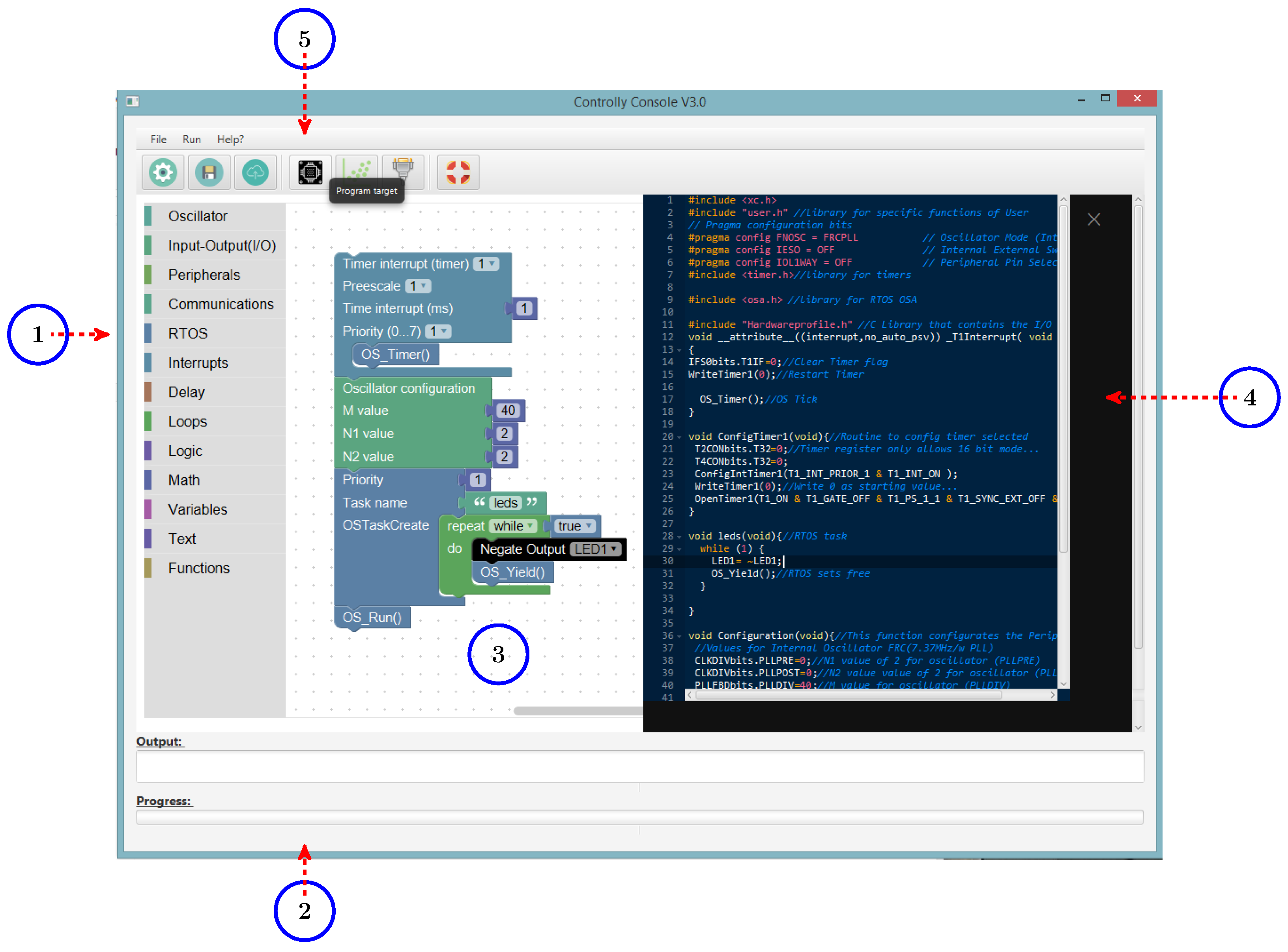
3.1.1. Presentation Layer

The Presentation Layer is composed of the User Interface (UI) of the application. Firstly, the UI is composed of a project wizard that helps the user with some parameters such as the paths for the compiler and the project, the type of board for the models (dsPIC 33FJ128GP804 and dsPIC 33FJ128MC802) and the communication port to use, e.g., COM1 or COM2, to transfer the created visual algorithm towards the development board. The communication between the development board and the application is managed through a virtual serial port with the USB feature Communication Device Class (CDC) [28].
Secondly, the UI includes a working area in which the students or users can build their algorithms based on the different graphical blocks designed in Blockly and distributed by categories. Thus, a specific C language generator for the XC16 compiler was developed in this platform. The generator converts every block in the C language equivalent and the UI shows this transformation in a tab in real-time. Thereby, students or users can observe the respective code with the configuration of the registers in the DSCs’ architecture, helping to learn programming and the implementation related to these devices.
Table 1 and Table 2 show a summary that condenses the designed categories with some examples.
The elements in Table 1 and Table 2 are explained below.
  • Oscillator: In this category, the user can configure the oscillator of the DSC. For the dsPICs 33FJ128GP804 and 33FJ128MC802, the equation that defines their operation frequency in Hz is the following:
    F c y = F o s c 2 = F i n ( M N 1 · N 2 )
    where F i n is the frequency of the internal FRC oscillator (7.37 MHz), F o s c is the output frequency of the Phase-Locked Loop (PLL), M is the PLL multiplier and N 1 and N 2 compound the PLL postscale. The values of N 1 , N 2 , and M are established by the user. For instance, when N 1 = 2, N 2 = 2, M = 40, these values yield a frequency of 36.85 MHz (36.85 MIPS). The graphical block converts the previous values in the respective code for the registers involved in the configuration of the oscillator, in this case CLKDIV and PLLFBD.
  • Input–Output: In this category are located the blocks for reading and writing the logical state of the DSC pins. Every block sets up the specific configuration register (TRISx) and assigns the logical state specified by the user (1 or 0). The pins that a user can employ are mapped in a C header file called <HardwareProfile.h>. This file contains the names of every pin provided by the manufacturer with a macro, e.g., the Pin1 in the application is RB12 in the DSC.
  • Peripherals: In this category, the user can configure the Analog to Digital Converter (ADC), Pulse Width Modulation (PWM) or Digital Analog Converter (DAC) peripherals. With respect to ADC, it was configured in 12-bit mode with an input voltage in the scale 0–3.3 V. The resolution for the ADC is given by Equation (2).
    3.3 V 2 12 bits 0.81 mV bit
    The block ADC Single reads the ADC channel selected by the user and returns an integer variable with the respective value in 12-bit. The block ADC Multiple Channels reads simultaneously up to four channels and returns the values in a set of preloaded variables (L0, L1, L2, and L3). The user must declare them, employing the category variables available in Blockly. In addition, this block uses the Timer 3 of the DSC to sample the indicated channels. PWM was configured in 10-bit mode with the XC16 library <pwm.h>. Four channels could be selected with the designed block. Moreover, the user can adjust the frequency in Hz and the pre-scale when a value for the register OCxR (Duty cycle register) is outside the maximum value in a 16-bit architecture. The pre-scale decreases this value.
    Regarding DAC, the block configures the device MCP4822 [29], which is a 12-bit DAC in a range from 0 to 3.3 V. This device operates with SPI protocol and it contains a single register to write the digital value to convert. The user must indicate an integer variable and one channel (A or B) to write a voltage value in the mentioned scale. For instance, when the user writes the value 2048, it will correspond to the analog value of 1.65 V.
  • Communications: This category contains several blocks to handle the UART peripheral with a default baud rate of 57,600. The blocks were designed utilizing the XC16 library <UART.h>. The library starts up the UART peripheral with the parameters specified by the user (interrupts in transmission or reception, addressing mode in eight or nine bits, interruption priority, etc.). Additionally, several functions were developed to transform either an integer or float variable in a string ready to transmit. The category has several blocks to writing and reading data: UART write text, UART write integer, UART write float and UART read data.
  • RTOS: For the platform, OSA was selected, which is a small RTOS compatible with dsPIC. OSA [30] is a cooperative multitasking RTOS that uses, in this case, Timer 1 to generate the Tslice for the different assigned tasks. In a cooperative RTOS, each tasks is executed periodically with a time provided by the system scheduler [31]. In the category, some blocks were designed to create and run tasks with priority in the range 0–7, where 0 is the highest level of priority and so on. A Java class copies the contents (folders and subfolders) of this RTOS into the user’s folder to compile with XC16. An example of code with the blocks is shown in Algorithm 1.
  • Interrupt: In this category, a timer interrupt was designed with the associated Interruption Service Routine (ISR). The graphical block contains several inputs such as pre-scale, clock tick between interrupts in ms and priority in the range 0–7. These elements serve to open and configure the timer selected by the user. The block operates with the frequency provided by the oscillator block that the student must configure previously. An “Interrupt” is a key concept because it allows understanding the architecture of any embedded system, in this case, concerning the DSCs. As concept, Di Jasio [32] defined an interrupt as an external or internal event that requires a quick CPU intervention. A code example with this block is shown in Algorithm 2 with a time between interrupts of 1 ms, a DSC frequency of 36.86 MHz and 1:1 pre-scale.
  • Delay: In this category, several blocks for delays in ms and μs, and instruction cycles were designed. The XC16 library <libpic30.h> was employed to create the delays based on instruction cycles according to the frequency specified by the user. For example, for a frequency of 36.86 MHz and a delay of 10 ms, the block delay(ms) will return the statement _delay32(368500).
  • Functions: In this category, the user can create C functions either with or without return variable. In addition, the names and invoke parameters of each function must be defined by the user as global variables. The functions make the code more readable and organized for the students.
Algorithm 1 Example of generated code for the RTOS (OSA).
//Task (Pin oscillator)
void Task2(void){
     while(1){//Task in infinite loop. Feature of cooperative RTOS.
         PIN1=1;//Write logical 1 on PIN1.
         OS_Delay(10000);//Task Delay (10000 clock ticks).
         PIN1=0;//Write logical 0 on PIN1.
         OS_Delay(10000);//Task Delay (10000 clock ticks).
         OS_Yield();//Return to scheduler.
     {
{
Algorithm 2 Example of generated code for the block (Timer interrupt).
#include <timer.h>//XC16 Timer Library
//Interruption Service Routine (ISR) for Timer1
void __attribute__((interrupt,no_auto_psv)) _T1Interrupt( void )
{
     IFS0bits.T1IF=0;//Clear Timer flag
     WriteTimer1(0);//Restart Timer
}
//Routine to configure the selected timer
void ConfigTimer1(void){
     T2CONbits.T32=0;//Timer register in 16-bit mode
     T4CONbits.T32=0;
     ConfigIntTimer1(T1_INT_PRIOR_0 & T1_INT_ON ); //Set-up of Timer1.
     WriteTimer1(0);//Write 0 to the Timer
     OpenTimer1(T1_ON & T1_GATE_OFF & T1_PS_1_1
     & T1_SYNC_EXT_OFF &T1_SOURCE_INT,36850);//Clock tick of 1ms.
}
Thirdly, a plotter and a serial port visualizer were added to the application. For the plotter, the Java library known as LiveGraph was utilized [33,34]. LiveGraph allows plotting up to 1000 data series simultaneously, with an update between 0.1 s and 1 h. Data are saved in the application in CSV format and the user should build a AV to plot the different data from the development board. A Java class embedded in the application captures the data incoming from the serial port and sends them to the framework of LiveGraph. With the CSV file, the users can export the data towards different mathematical environments such as MATLAB, Octave, etc. for further processing. When a user wants to plot data, the application will request the number of variables to plot, the update frequency and one option to buffer data. Data sampling can be stopped, closing the serial port from the application.
The serial port visualizer shows the user’s data, using the same COM port indicated in the project wizard. The serial port visualizer could allow the users to check whether their algorithm is correct.
As mentioned above, the e-learning tool Xerte was employed as support for the construction of the educational materials of the platform that begin with the concepts of the DSCs and the embedded systems to end in the features of the application. Xerte provides a complete environment to develop materials with resources such as videos, quizzes, games or interactive web pages that accompany the learning process of the student.
Finally, an overall perspective of the UI with its main components and the educational materials are depicted in Figure 2 and Figure 3, respectively.

3.1.2. Application Layer

The core of the software component of the platform is composed of the objects WebView [35] and WebEngine [36] available in JavaFX, which interact with Blockly to get the respective code for the DSCs. A WebEngine is a non-visual component to manage a specific webpage, which allows invoking the different functions made in JavaScript into Blockly. Because Blockly is web-oriented, a WebEngine is a useful component to exchange data with this application. The WebView displays adequately the content of a webpage into a scene in JavaFx. The scenes posed in this section were created with the software JavaFX Scene Builder 2.0 [37] and their respective controllers with NetBeans IDE 8.2. The Application Layer is composed of the elements: WebView, WebEngine, LiveGraph, Ace code editor [38] and some XC16 libraries. An actor can select seven options in the UI: Project Wizard, Program, Plot, Serial Port Visualizer, Help, Open and Save. The Unified Modeling Language (UML) sequence diagram for the option Project Wizard is depicted in Figure 4.
When a user clicks on the button Project Wizard, this event opens a scene that asks for some parameters such as the user’s folder path, the compiler’s path and the serial port for the communication with the development board. These elements are saved as constructors in a Java Class to be used with other methods. Posteriorly, another class copies all files and folders needed into the user’s folder. Table 3 shows a description of these files.
Last in the sequence, Blockly is loaded into the WebView, employing the JavaFX constructor WebEngine() with the method load(String URL). The URL contains the local path for Blockly, which is found in the resources’ folder of the application. A tab in the workspace deploys in real-time the code for the elaborated AV, as illustrated in Figure 2. Moreover, the generated code is highlighted with the Ace code editor [38], which is a syntax highlighter for diverse statements in over 110 programming languages, including C.
Each block inside Blockly has two associated files: (1) a shape file with the definition of the graphical attributes; and (2) a file that describes the behavior’s block, that is, the returned C language code by the block. For instance, the block delay(ms) depicted in Table 2 is associated with the JavaScript function shown in Algorithm 3 for its behavior. In this algorithm, the value with the time in milliseconds (ms) is assigned to the variable OSCVal. Then, the code for the block is returned and injected by Blockly to be represented in the code tab for the user. As mentioned, this operation is made in real-time with the component WebView in JavaFX that allows to invoke the JavaScript functions nested in Blockly.
Algorithm 3 JavaScript Behavior function for the Block Delay (ms).
Blockly.Dart.delay=function() {//Delay function
     var OSCVal=Blockly.Dart.valueToCode(this,’Time’,
     Blockly.Dart.ORDER_ATOMIC);
     var code=__delay32(’+OSCVal+’);//Returned code for the block.
     return code;
};
The second option available in the UI is to program. The respective sequence diagram for this function is depicted in Figure 5.
The method GetUserCode() calls the JavaScript function (content()) that returns through a JavaScript alert the programming code for the blocks. A callback registered with the constructor (WebEngine) detects this alert and it proceeds to get the code as a string. Subsequently, the content of this string is saved in a C file to be compiled with the compiler XC16, employing its command line. The previous operation is executed by the class Runtime in JavaFX. The command line option provides the different instructions to compile and generate the Hex file to program the DSC and a report with errors, memory distribution (RAM, Flash), etc.
With the Hex file, the method CallBootloader() invokes the Bootloader ds30 Loader (free edition) [39]. By definition, a bootloader is a small piece of code inside the DSC that manages its programming mode through some peripheral such as UART, CAN or USB. For the bootloader, an assembler file provided by the developer was loaded into the program memory of the DSC with a default baud rate of 57,600. Some modifications were made to this file according to the remappable pins of the UART peripheral of the DSC. The bootloader is executed by the application in the command line mode, in which a string command with the path for the Hex file, the name of the COM port, the reset command and the device to program is provided.
When a reset occurs by the mentioned command, the DSC starts with the bootloader during 5 s, waiting for a new programming request from the application. When no programming request is made, the bootloader gives the control to the code loaded previously in the flash memory of the DSC. Independently, the bootloader opens and closes the serial port and it sends the Hex file towards the DSC, managing all the process.
Concerning the option plot, the UML sequence diagram for this option is represented in Figure 6.
To create an instance for the plotter, the method OpenPlotter() is invoked and an object is returned by it. This object opens the different elements of the class LiveGraph. A new scene is deployed to the user that asks the number of variables to plot. Hence, the result of this transaction is a new window in which the user can see and update the data, as shown in Figure 7.
Afterwards, the serial port (COM) is opened and it gets the data incoming from the development board in a buffer. Meanwhile, a method in the application saves the data in a CSV file.
The user also can save or open the designed AV and to request help from the application. The programming structure of these functions is summarized in the sequence diagrams in Figure 8.
Whether a user wants to open or save the AV created, Blockly contains the JavaScript function Blockly.Xml.domToPrettyText that converts the AVs into an XML file, which is saved in the user’s folder. The Java class WebEngine calls the mentioned JavaScript function and it returns a text with the XML code in a JavaScript alert. The code is retrieved by means of a callback event in the application that detects this alert. In the same way, the XML file in the user’s folder can be upload to the application, recovering the AV made through the functions Blockly.Xml.textToDom and Blockly.Xml.domToWorkspace.
With the help of the application, it releases a new browser window with the URL to the Xerte materials, as depicted in Figure 3. To open this window, the application uses the Java class Desktop with the method browse.
Finally, a serial port visualizer was created through library, Java Simple Serial Connector (jSSC) [40], which implements the necessary methods to write and read data from the serial port. The library provides an asynchronous event to get data in a byte buffer that are converted to string and displayed in a JavaFx TextArea. Regarding the asynchronous event, it allows the user to execute other functions in the application with the serial port receiving data of the development board at the same time. Figure 9 shows the sequence diagram for this function. Below, it is shown how the hardware component of the platform interacts with the software application.

3.1.3. Hardware Abstraction Layer

The communication between the software and the hardware components in the application is managed by the Hardware Abstraction Layer (HAL), which is composed of the bootloader (ds30 Loader) and the Java library (jSSC). These elements form the HAL because they interchange information between the software and hardware elements in the application. As mentioned, the bootloader allows programming the DSC with the Hex file provided by the compiler and it is composed of two overall files, namely, the firmware and a console that is invoked through a command line, sending the Hex file towards the DSC. Table 4 shows a summary of the files provided in the firmware with their description.
The firmware should be modified according to the specifications of the DSC in assembler (asm30). For instance, in the hardware, pins RB9 and RC6 of the dsPIC 33FJ128GP804 serve for reception and transmission of data, respectively. Thus, the RPINR19 and RPOR11 registers were configured for these functions and the FRC oscillator was enabled with the default frequency of 7.37 MHz. With these parameters, the bootloader is programmed in the DSC, utilizing a programmer such as PICkit 3 [41] or ICD3 [42].

3.1.4. Application Summary

Finally, a summary with the software features of the platform is described in Table 5. The application was tested in a PC with the following parameters:
  • Processor: Intel(R) Core (TM) i5-4460T @ 1.9 GHz.
  • Installed memory RAM: 8 GB
  • System type: 64-bit operating system. (Windows 8).
  • Local disc capability: 1.5 TB
  • Java version: 1.8.0.121
The application was also tested in a PC based on Windows 7 with similar features. To complement the previous information, VisualVM 1.4.2 [43] was used, which is a software that monitors and troubleshoots applications running on Java. The analysis information provided by this software is shown in Figure 10.
The information in Figure 10 was retrieved when the AV represented in the Example 1 in Section 4 was built. In this case, the peak CPU usage in percentage was 31% with an average heap size for Java of 22 MB.

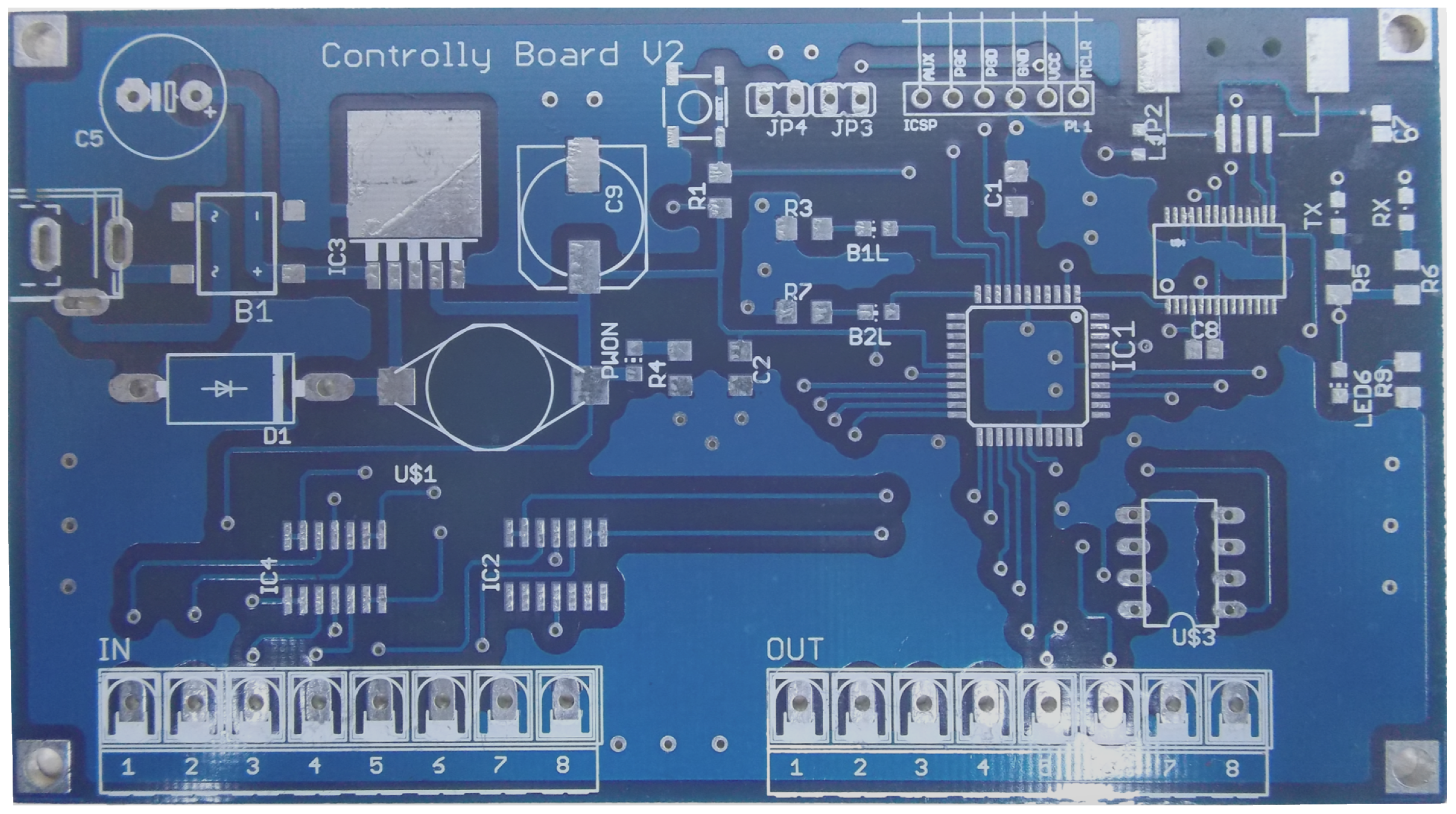
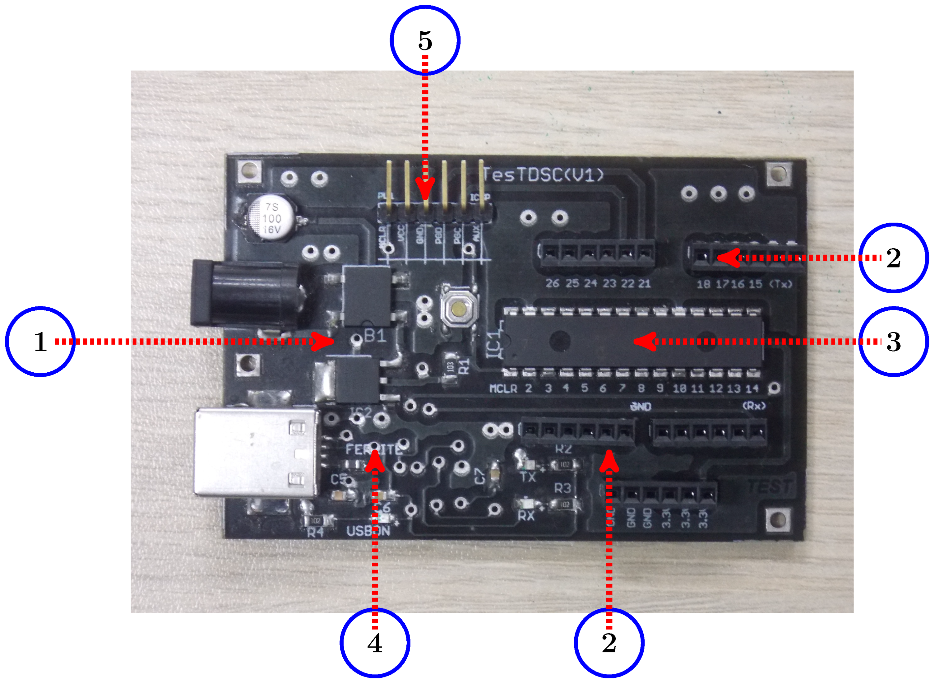
3.2. Hardware Component

Two models of low-cost development boards were built as hardware components in the platform. They are composed of the DSCs (dsPIC 33FJ128GP804 or dsPIC 33FJ128MC802) with the respective conditioning for their inputs, a 3.3 V power supply and a UART to USB bridge (FT232RL). Each development board contains six analog or digital inputs (depending on the function assigned by the user), four digital outputs and two DAC outputs (channels A and B). A scheme with the main components of the developments boards is depicted in Figure 11.
The analog inputs are conditioned by voltage followers built with Operational Amplifiers (Op-Amps) (MCP6004) [44] that limit the voltage of the input signals to a range of 0–3.3 V and reduce their noise. In addition, the selected Op-Amps are rail-to-rail, that is, the output voltage ( V o u t ) of each when the Op-Amp is in saturation mode is approximately V o u t = V s a t 150 mV with V s a t 3.3 V . This feature allows the user to have a full span of the applied analog signals.
For the inputs, an example of schematic with the voltage followers is presented in Figure 12.
The user connects their signal to the terminal blocks (IN-1 to IN-6) that are wired to the Op-Amps (MCP6004). This hardware device has four Op-Amps with a 1 MHz Gain Bandwidth Product (GBWP), 90° phase margin, a power supply voltage in the range of 1.8–6 V and a quiescent current of 100 μA. The device is suitable for the hardware requirements of the platform. The development boards also have a reset push button and one In-Circuit Serial Programming (ICSP) header for a programmer such as PICkit 3 or ICD3. For the design of the application, the low-cost programmer (PICkit 3) from Microchip Inc. was used.
As regards to the power supply of 3.3 V, it was designed through a step-down voltage regulator (LM2576) [45] with a maximum load current of 3 A for the model (dsPIC 33FJ128GP804). The current consumption for a frequency of 40 MIPS in the DSC is roughly 0.17 A. The regulator provides thermal shutdown and current limit protection with a efficiency ( η ) around 88% for the parameters V i n = 18 V and I L o a d = 3 A. Figure 13 illustrates the schematic for the power supply.
For the model dsPIC 33FJ128MC802, a voltage regulator (LM1117-3.3) with a maximum load current of 800 mA was used. Concerning the UART to USB bridge, it was built with the chip FT232RL [46] from FTDI that has a CDC emulation and it transfers the USB data to the UART peripheral for the DSC. Figure 14 shows the followed schematic for this device in the two models of development board.
The previous elements compose the development boards depicted in Figure 15, Figure 16 and Figure 17 for the dsPIC 33FJ128GP804 and dsPIC 33FJ128MC802. The design of each development board can be modified effortlessly to use other type of dsPICs, e.g., the dsPIC 33FJ128GP802. Each development board has an average cost of US$30.

4. Experiments

This section exposes several examples with the platform, employing the mentioned elements of software and hardware. The main purpose of these examples is to provide a description of some usage cases that can be built with the platform.

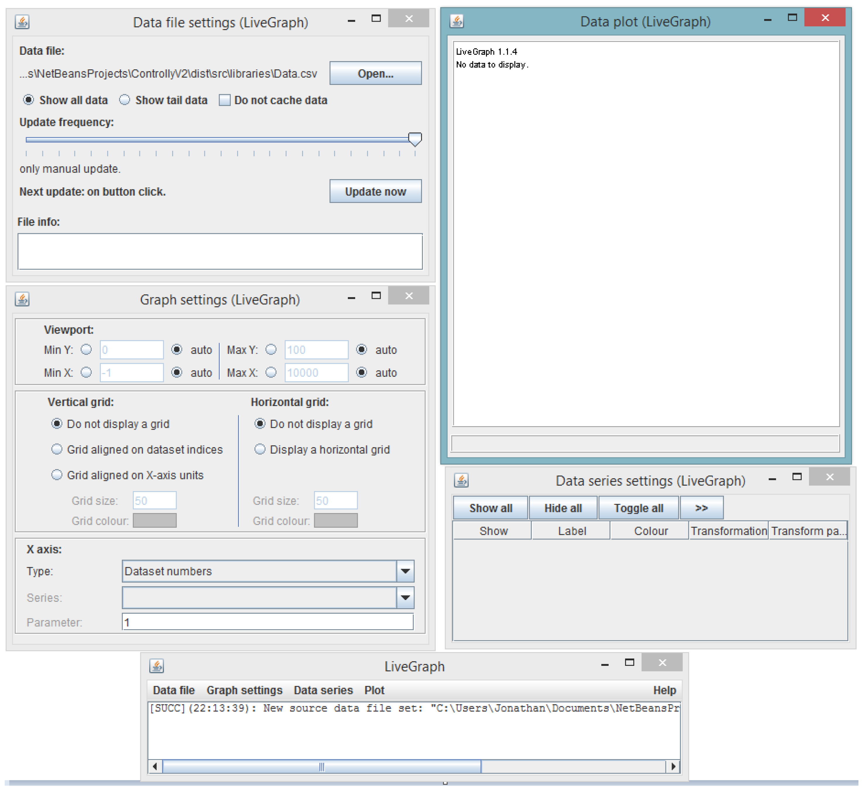
4.1. Example 1: ADC plotting

In this example, the analog data on input (1) of the development board is plotted. The steps involved are as follows:
  • Plug-in the development board to a PC. Configure the project in the application using the project wizard.
  • Create the AV according to the specifications of a design. Use the palette to get the different graphical blocks that are needed in the AV. Program the development board with this.
  • Debug the AV. For this example, connect a potentiometer on input 1.
  • Open the plotter, specifying the number of variables to plot, in this case, 1.
  • Click on the run button to start the plotter.
Taking into account the previous steps, Figure 18 and Figure 19 show the procedure starting with the flow diagram, Figure 20 illustrates the plot with the data from ADC peripheral and Figure 21 depicts the testing environment for this example:
The user declares the variable i that reads the value of the ADC. This value is sent to the UART peripheral, employing the block UART send (integer). The program runs continuously in an infinite loop.

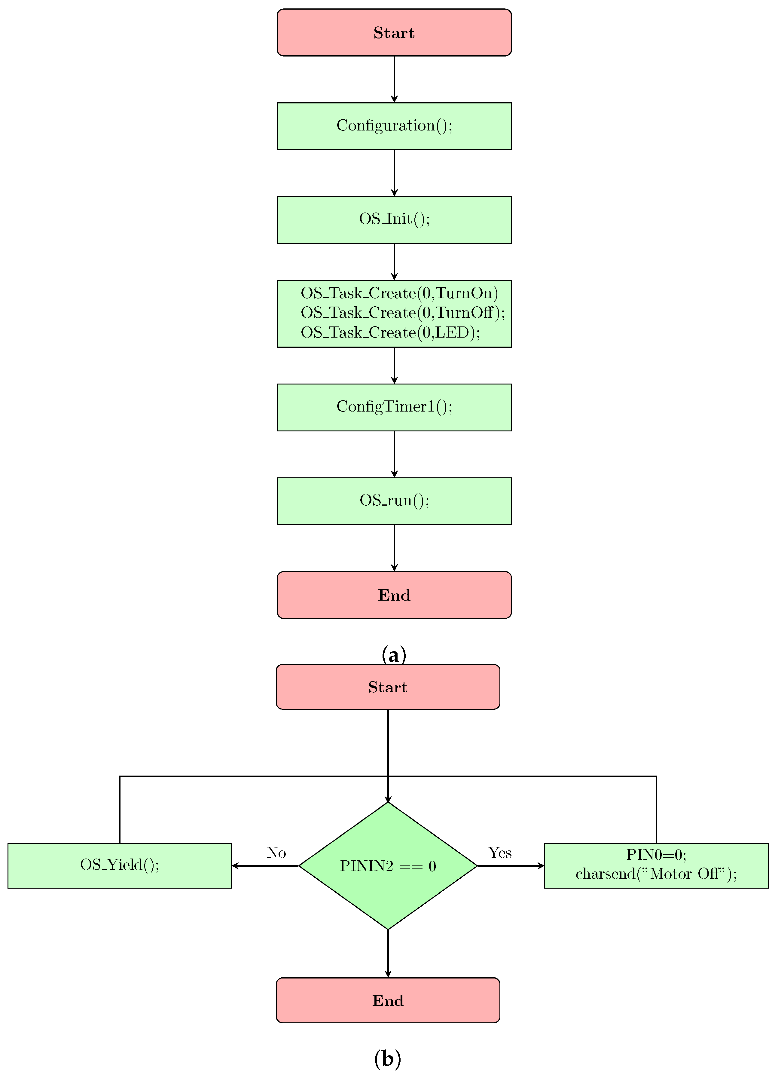
4.2. Example 2: RTOS

This example uses the RTOS (OSA) to start and stop an AC Induction Machine (ACIM). The RTOS reads two switches (start and stop) and also sends the texts Motor On, Motor Off to the serial port, relying on the state of the ACIM. For this example, the steps are as follows:
  • Plug-in the development board to a PC. Configure the project in the application using the project wizard.
  • Create the AV according to the specifications of a design. Indicate the name of the tasks for the RTOS (TurnOn, Turnoff). To use the RTOS, a Timer (1) interrupt must be configured.
  • Program the development board with the AV built in Step 2.
  • Debug the AV. Connect two switches with their respective pull-up resistors to inputs 2 and 3 of the development board. In addition, connect a relay and an AC contactor for the ACIM with their protections.
  • Start and stop the ACIM. Test the message transmission on the serial port visor in the GUI of the platform.
Figure 22, Figure 23 and Figure 24, show the flow diagrams, the AV and the testing environment for the example.

5. Assessment

To assess the platform, a survey was applied to 30 sophomores (n = 30) in the periods 2017-II and 2018-I. The students belonged to the program of Electronic Technology at UNIMINUTO university and they were informed and invited to the study conducted with the platform. All students decided to participate in this study giving their approval. This assessment provides the standpoint of the students that used the platform in aspects such technical as educational, which could give a perspective on its use. Table 6 sums-up the questions and answers of the survey.
Questions 1 and 3 evaluated the platform at the technical level. Due to some presented bugs that were fixed, the average grade provided by the students was 8.5. In the same way, Question 3 indicated what elements the students considered relevant about the platform. The answer to Question 2 showed the learning that the students had with the platform in comparison with the traditional educational method of embedded systems. The traditional method to teach embedded systems at Uniminuto University typically consists of employing a text-based structured programming, flow diagrams and microcontrollers (PIC) in projects, instead of the AVs and DSCs. The difference between this traditional method and the learning with the DSCBlocks platform lies, as mentioned above, in the possibility to design and implement in real-time an algorithm through AVs, in which the students can see different algorithmic procedures and the registers involved in the DSC’s architecture. Nevertheless, a dedicated questionnaire to assess the learning with the platform is a research question still needs to be addressed.
In addition to the previous questions, the students were inquired in the same survey about the elements that they would improve in the platform. The students agreed with the need to have more graphical blocks to deploy protocols as I2C, CAN or SPI. Moreover, the students indicated that the methodology with the platform needs to be longer to fulfill the proposed learning outcomes.
The concept of the platform in the educational context arises on the one hand due to the lack of open-source resources pertaining to embedded systems area and on the other hand the problems detected in the algorithmic thinking that limit somehow the learning of programming in the students. In this way, the platform is an educational alternative that could address the described issues.
During 2017-II and 2018-I, the students employed the platform in different types of tasks into the curriculum of the microcontrollers with an average class time of 2 h per week during 15 weeks. The class sessions varied between the usage of the developed block-based language with the platform and text-based programming with MPLABX IDE [47] in a similar process mentioned by the authors of [15,26].
This method is suitable because the students must understand the DSC architecture with the different configuration registers involved in it and they must familiarize with the development environment (compiler and IDE) in order to program the DSCs. Thus, the students used the text-based programming in the first classes of the subject. Then, the students employed the platform in different laboratories with the visual language, considering the different designed AVs. In addition, the students debugged their algorithms in real practices, which represents an advantage over the simulation.
The educational process raised with the platform took into account four moments: abstraction, design, practice and arguing. These moments are described as follows:
  • Abstraction: In this stage, the class session was focused on theoretical aspects regarding the DSC’s architecture (registers, ports, peripherals, data bus, etc.) and the parameters such of the compiler XC16 as of MPLABX IDE.
  • Design: The students developed an algorithm for a proposed problem, alternating between the text coding and the AVs. The algorithms required the usage of peripherals, ports, variables and loops, which are elements commonly used in the embedded systems area.
  • Practice: The students implemented the designed algorithm in several proposed laboratories, typically, clustering industrial devices such as AC motors, AC contactors, relays and sensors.
  • Arguing: The students explained the developed algorithms in their structure. For example, when the students configured a port or peripheral for certain design, they explained the configuration of the registers, loops, variables or functions involved in this operation.
According to the observations made in the class sessions and the indicated poll, it is possible to say that the platform is suitable and reliable to learn the concepts of the embedded systems with the DSCs, although it needs to be alternated with the text-based programming. In addition, the arguing concerning the developed AVs is a key process because the students explain the different mechanisms that structure an algorithm from their learning perspective.

6. Discussion

In agreement to the described technical and educational aspects and the assessment provided by the students, it can be concluded that the platform is suitable to learn the different concepts relating to the DSCs through AVs as educational way in the construction and understanding of an algorithm that requires the usage of these devices. In addition, the platform allows the user to design and test applications in the embedded systems area due to the number of graphical blocks to handle diverse peripherals, ports, RTOS and its user-friendly interface. With the platform, the students can observe the configuration for the registers, loops, functions and variables involved in the functioning of the DSCs, following an algorithmic structure.
DSCBlocks was tested with industrial devices (ACIMs, AC contactors, relays, etc.) to evaluate its robustness, as depicted in Example 2. Furthermore, the graphical blocks that compound the application were divided into 28 functions, distributed in different categories and 120 codes were tested.
Conceptually, open-source hardware [48] is composed of physical technological artifacts, e.g., PCB layouts, schematics, HDL source codes, mechanical drawings, etc., that could be used in other projects or designs in some cases with the respective General Public License (GPL). This work is entirely open-source in hardware and software, that is to say, a user can modify the structure of hardware and software according to the requirements of a design only with an attribution requirement. Finally, the importance of this work lies in that the platform addresses the lack of open-source educational resources for the embedded systems regarding the DSCs. Although the hardware devices employed in the application are dsPICs, the followed schema could adapt to other DSC’s architectures, e.g., ARM, Texas Instruments or Atmel.
One important difficulty that deserves to be mentioned in the design of the interface is the modification of Blockly, because the documentation concerned was not totally accessible at the time to create the XC16 language generator and the graphical blocks. Blockly combines many JavaScript functions that could confuse to a developer. The recommendation to overcome this issue is to adapt a preloaded language converter in Blockly. For example, to build the platform, a Dart language converter was adapted to its design requirements.
It is important to create open-source resources in software and hardware that contribute to the learning of the students or users in engineering areas such as control, embedded systems, power electronics or robotics. This type of resources could become a source of knowledge that deserves to be shared and can be used as reference guides in the construction of different types of applications and designs in the academic and industrial sectors. Besides, the users can modify the structure of these resources, generating new developments that could help to solve diverse problems in the engineering context.

7. Conclusions and Further Work

In this paper, an open-source platform for embedded systems called DSCBlocks is presented. The main interest of the platform was to provide an open, flexible, suitable and efficient environment to program DSCs through Algorithm Visualizations (AVs). Furthermore, the platform aims to cope with the lack of open-source resources in the area of the embedded systems, specifically associated with the DSCs.
As described above, the AVs have important advantages for the students or users that want to design any type of algorithms in order to learn embedded systems. With the AVs, the students can observe the different configurations of the registers of the DSCs for different peripherals and ports; create variables, loops, and functions; and can see the algorithmic procedures in real-time, helping to understand the architecture of these devices.
The assessment provided by the students suggests that the platform is reliable for the design and the implementation of different types of algorithms needed in embedded systems, and it allows the learning of the concepts concerning this area.
Although the platform has been conceived for academic work, the software and hardware components can be adapted effortlessly for any kind of project that employs DSCs. Further research of the platform will consist, on the one hand, in the design of new blocks for communication peripherals such as as I2C or CAN. In addition, the development board will be expanded to give a better functionality to the users for applications that utilize, e.g., Liquid Crystal Displays (LCDs), sensors and actuators that require a greater number of inputs and outputs. On the other hand, it will make an educational study of the platform to know the implications of it in the learning of the students.

Supplementary Materials

Complete version of DSCBlocks for PC or laptop is available online at http://www.seconlearning.com/DSCBlockV2/DSCBlocksFull.zip. GitHub repository of the application is available online at https://github.com/Uniminutoarduino/DSCBlocksV2. Xerte materials are available online at http://seconlearning.com/xerte/play.php?template_id=5. DSCBlocks web application is available online at http://seconlearning.com/DSCBlockV2/BlocklyOPt/demos/code/index.html.

Author Contributions

The author carried out the conceptualization, design, implementation of the platform and writing of the paper.

Acknowledgments

This work was supported by the Control Research Incubator (SeCon) funded by the Corporación Universitaria Minuto de Dios (UNIMINUTO).

Conflicts of Interest

The author declares no conflict of interest.

References

  1. Microchip Technology Inc. dsPIC ® Digital Signal Controllers The Best of Both Worlds. Available online: http://www.farnell.com/datasheets/133476.pdf (accessed on 24 July 2018).
  2. Aspencore. 2017 Embedded Markets Study. Available online: https://m.eet.com/media/1246048/2017-embedded-market-study.pdf (accessed on 28 July 2018).
  3. Clarke, J.; Connors, J.; Bruno, E.J. JavaFX: Developing Rich Internet Applications; Pearson Education: London, UK, 2009. [Google Scholar]
  4. Heckler, M.; Grunwald, G.; Pereda, J.; Phillips, S.; Dea, C. Javafx 8: Introduction by Example; Apress: New York, NY, USA, 2014. [Google Scholar]
  5. Microchip Technology Inc. dsPIC 33FJ128GP804 Datasheet. Available online: https://www.microchip.com/wwwproducts/en/dsPIC33FJ128GP804 (accessed on 31 July 2018).
  6. Microchip Technology Inc. dsPIC 33FJ128MC802 Datasheet. Available online: https://www.microchip.com/wwwproducts/en/dsPIC33FJ128MC802 (accessed on 31 July 2018).
  7. Microchip Technology Inc. dsPIC 33F Product Overview. Available online: https://cdn.sos.sk/productdata/fb/55/a9c85743/dspic33fj256gp710-i-pf.pdf (accessed on 31 July 2018).
  8. Törley, G. Algorithm visualization in teaching practice. Acta Didact. Napoc. 2014, 7, 1–17. [Google Scholar]
  9. Shaffer, C.A.; Cooper, M.L.; Alon, A.J.D.; Akbar, M.; Stewart, M.; Ponce, S.; Edwards, S.H. Algorithm visualization: The state of the field. ACM Trans. Comput. Educ. (TOCE) 2010, 10, 9. [Google Scholar] [CrossRef]
  10. Google LLC. Blockly Demo: Code. Available online: https://developers.google.com/blockly/ (accessed on 31 July 2018).
  11. Fraser, N. Ten things we’ve learned from Blockly. In Blocks and Beyond Workshop (Blocks and Beyond); IEEE Computer Society: Washington, DC, USA, 2015; pp. 49–50. [Google Scholar] [CrossRef]
  12. Microchip Technology Inc. MPLAB ® XC16 C Compiler User’s Guide. Available online: http://ww1.microchip.com/downloads/en/DeviceDoc/MPLAB%20XC16%20C%20Compiler%20Users%20Guide%20DS50002071.pdf (accessed on 28 July 2018).
  13. Ball, S.; Tenney, J. Xerte—A User-Friendly Tool for Creating Accessible Learning Objects. In International Conference on Computers for Handicapped Persons; Springer: Berlin/Heidelberg, Germany, 2008; pp. 291–294. [Google Scholar] [CrossRef]
  14. González, G.G. Xerte Online Toolklts Y El DiseÑo De Actividades Interactivas Para Fomentar La AutonomÍa De Aprendizaje en Ele. La Red Y Sus Aplicaciones en La EnseÑanza-Aprendizaje Del EspaÑol Como Lengua Extranjera. Asociación Para La EnseÑanza Del EspaÑol Como Lengua Extranjera, 2011; pp. 653–662. Available online: https://cvc.cervantes.es/ensenanza/biblioteca_ele/asele/pdf/22/22_0063.pdf (accessed on 17 August 2018).
  15. Hundhausen, C.D.; Douglas, S.A.; Stasko, J.T. A meta-study of algorithm visualization effectiveness. J. Vis. Lang. Comput. 2002, 13, 259–290. [Google Scholar] [CrossRef]
  16. Rößling, G.; Naps, T.L. Towards Improved Individual Support in Algorithm Visualization. In Proceedings of the Second International Program Visualization Workshop, Århus, Denmark, 22–24 November 2002; pp. 125–130. [Google Scholar]
  17. Pasternak, E.; Fenichel, R.; Marshall, A.N. Tips for creating a block language with blockly. In Proceedings of the Blocks and Beyond Workshop (B&B), Raleigh, NC, USA, 9–10 October 2017; pp. 21–24. [Google Scholar] [CrossRef]
  18. Weintrop, D.; Shepherd, D.C.; Francis, P.; Franklin, D. Blockly goes to work: Block-based programming for industrial robots. In Proceedings of the Blocks and Beyond Workshop (B&B), Raleigh, NC, USA, 9–10 October 2017; pp. 21–24. [Google Scholar] [CrossRef]
  19. Angulo, I.; García-Zubía, J.; Hernández-Jayo, U.; Uriarte, I.; Rodríguez-Gil, L.; Orduña, P.; Pieper, G.M. RoboBlock: A remote lab for robotics and visual programming. In Proceedings of the Experiment@ International Conference (exp. at’17), Faro, Portugal, 6–8 June 2017; pp. 109–110. [Google Scholar] [CrossRef]
  20. Serna, M.; Sreenan, C.J.; Fedor, S. A visual programming framework for wireless sensor networks in smart home applications. In Proceedings of the International Conference on Intelligent Sensors, Sensor Networks and Information Processing, Singapore, 7–9 April 2015. [Google Scholar] [CrossRef]
  21. Ariza, J.A. Controlly: Open source platform for learning and teaching control systems. In Proceedings of the 2015 IEEE 2nd Colombian Conference on Automatic Control (CCAC), Manizales, Colombia, 14–16 October 2015; pp. 1–6. [Google Scholar] [CrossRef]
  22. Galán, D.; de la Torre, L.; Dormido, S.; Heradio, R.; Esquembre, F. Blockly experiments for EjsS laboratories. In Proceedings of the Experiment@ International Conference (exp. at’17), Faro, Portugal, 6–8 June 2017; pp. 139–140. [Google Scholar] [CrossRef]
  23. Bak, N.; Chang, B.; Choi, K. Smart Block: A Visual Programming Environment for SmartThings. In Proceedings of the 2018 IEEE 42nd Annual Computer Software and Applications Conference (COMPSAC), Tokyo, Japan, 23–27 July 2018; Volume 2, pp. 32–37. [Google Scholar] [CrossRef]
  24. Khamphroo, M.; Kwankeo, N.; Kaemarungsi, K.; Fukawa, K. MicroPython-based educational mobile robot for computer coding learning. In Proceedings of the 2017 8th International Conference of Information and Communication Technology for Embedded Systems (IC-ICTES), Chonburi, Thailand, 7–9 May 2017; pp. 1–6. [Google Scholar] [CrossRef]
  25. Marron, A.; Weiss, G.; Wiener, G. A decentralized approach for programming interactive applications with javascript and blockly. In Proceedings of the 2nd Edition on Programming Systems, Languages and Applications Based on Actors, Agents, and Decentralized Control Abstractions, Tucson, AZ, USA, 21–22 October 2012; pp. 59–70. [Google Scholar]
  26. Matsuzawa, Y.; Tanaka, Y.; Sakai, S. Measuring an impact of block-based language in introductory programming. In International Conference on Stakeholders and Information Technology in Education; Springer: Berlin/Heidelberg, Germany, 2016; pp. 16–25. [Google Scholar] [CrossRef]
  27. Chtourou, S.; Kharrat, M.; Ben Amor, N.; Jallouli, M.; Abid, M. Using IOIOAI in introductory courses to embedded systems for engineering students: A case study. Int. J. Electr. Eng. Educ. 2018, 55, 62–78. [Google Scholar] [CrossRef]
  28. Microchip Technology Inc. USB CDC Class on an Embedded Device. Available online: http://www.t-es-t.hu/download/microchip/an1164a.pdf (accessed on 2 August 2018).
  29. Microchip Technology Inc. MCP4822 Datasheet. Available online: https://people.ece.cornell.edu/land/courses/ece4760/labs/f2015/lab2_mcp4822.pdf (accessed on 3 August 2018).
  30. RTOS. What Is OSA? Available online: http://wiki.pic24.ru/doku.php/en/osa/ref/introduction/intro (accessed on 7 August 2018).
  31. Heath, S. Embedded Systems Design; Elsevier: Amsterdam, The Netherlands, 2002. [Google Scholar]
  32. Di Jasio, L. Programming 16-Bit PIC Microcontrollers in C: Learning to Fly the PIC 24; Elsevier: Amsterdam, The Netherlands, 2007. [Google Scholar]
  33. Sain, M.; Lee, H.; Chung, W. MUHIS: A Middleware approach Using LiveGraph. In Proceedings of the 2009 International Multimedia, Signal Processing and Communication Technologies, Aligarh, India, 14–16 March 2009; pp. 197–200. [Google Scholar] [CrossRef]
  34. Paperin, G. LiveGraph Summary. Available online: https://sourceforge.net/projects/live-graph/ (accessed on 9 August 2018).
  35. Oracle Corporation. WebView JavaDoc. Class WebView. Available online: https://docs.oracle.com/javase/8/javafx/api/javafx/scene/web/WebView.html (accessed on 9 September 2018).
  36. Oracle Corporation. WebEngine JavaDoc. Class WebEngine. Available online: https://docs.oracle.com/javase/8/javafx/api/javafx/scene/web/WebEngine.html (accessed on 9 September 2018).
  37. Oracle Corporation. JavaFX Scene Builder 2.0. Available online: https://www.oracle.com/technetwork/java/javase/downloads/sb2download-2177776.html (accessed on 28 July 2018).
  38. Mozilla Foundation. Ace Code Editor. Available online: https://ace.c9.io/ (accessed on 9 September 2018).
  39. Gustavsson, M. ds30 Loader. Available online: https://www.ds30loader.com/ (accessed on 28 July 2018).
  40. jSSC (Java Simple Serial Connector). Available online: https://code.google.com/archive/p/java-simple-serial-connector/ (accessed on 28 August 2018).
  41. Microchip Technology Inc. Pickit3 Datasheet. Available online: https://ww1.microchip.com/downloads/en/DeviceDoc/51795B.pdf (accessed on 12 October 2018).
  42. Microchip Technology Inc. ICD3 Datasheet. Available online: http://ww1.microchip.com/downloads/en/DeviceDoc/50002081B.pdf (accessed on 12 October 2018).
  43. Jiri Sedlacek, T.H. VisualVM: All-in-One Java Troubleshooting Tool. Available online: https://visualvm.github.io/index.html (accessed on 10 October 2018).
  44. Microchip Technology Inc. MCP6004 Datasheet. Available online: http://ww1.microchip.com/downloads/en/DeviceDoc/21733j.pdf (accessed on 28 August 2018).
  45. Instruments, T. LM2576 Voltage Regulator Datasheet. Available online: http://www.ti.com/lit/ds/symlink/lm2576.pdf (accessed on 28 August 2018).
  46. FTDI Chip. FT232RL Datasheet. Available online: https://www.ftdichip.com/Support/Documents/DataSheets/ICs/DS_FT232R.pdf (accessed on 28 July 2018).
  47. Microchip Technology Inc. MPLABX IDE. Available online: https://www.microchip.com/mplab/mplab-x-ide (accessed on 10 October 2018).
  48. Ray, P.P.; Rai, R. Open Source Hardware: An Introductory Approach; Lap Lambert: Saarbrücken, Germany, 2013. [Google Scholar]
Figure 1. Main software components of the platform by layers.
Electronics 08 00228 g001
Figure 2. Overall components of the UI: (1) blocks palette; (2) console output; (3) working area; (4) real-time code tab; and (5) toolbar.
Electronics 08 00228 g002
Figure 3. Educational materials in Xerte (Spanish version). (1) example of educational material; (2) glossary option of Xerte; and (3) embedded resource (interactive web page) with AVs.
Electronics 08 00228 g003
Figure 4. UML sequence diagram for the option Project Wizard.
Electronics 08 00228 g004
Figure 5. UML sequence diagram for the option Program.
Electronics 08 00228 g005
Figure 6. UML sequence diagram for the option Plot.
Electronics 08 00228 g006
Figure 7. LiveGraph components composed of windows (plotter and update data).
Electronics 08 00228 g007
Figure 8. UML sequence diagrams for the functions Open, Save and Help.
Electronics 08 00228 g008
Figure 9. UML sequence diagram for the function Serial Port Visualizer.
Electronics 08 00228 g009
Figure 10. Benchmark information for the application provided by VisualVM 1.4.2.
Electronics 08 00228 g010
Figure 11. Overall scheme of the development board by blocks inputs, outputs and power supply.
Electronics 08 00228 g011
Figure 12. Schematic of the inputs’ conditioning through voltage followers for the development boards.
Electronics 08 00228 g012
Figure 13. Schematic of the Power Supply with a step-down voltage regulator (LM2576). The connectors JP3 and JP4 provide voltage test points for the user designs.
Electronics 08 00228 g013
Figure 14. Schematic of the USB to UART bridge (FT323RL). The points RXD (Data reception) and TXD (Data transmission) are connected to dsPIC pins RB9 and RC6, respectively, for the dsPIC 33FJ128GP804.
Electronics 08 00228 g014
Figure 15. Development board’s solder screen.
Electronics 08 00228 g015
Figure 16. Overall appearance of the development board with dsPIC 33FJ128GP804: (1) power supply unit; (2) voltage followers; (3) inputs; (4) outputs; (5) DAC (MCP4822); (6) dsPIC 33FJ128GP804; (7) FT232RL (UART to USB bridge); and (8) ICSP header connector.
Electronics 08 00228 g016
Figure 17. Overall appearance of the development board with dsPIC 33FJ128MC802: (1) power supply unit; (2) input–output connectors; (3) dsPIC 33FJ128MC802; (4) FT232RL (UART to USB bridge); and (5) ICSP header connector.
Electronics 08 00228 g017
Figure 18. Flow diagram for Example 1.
Electronics 08 00228 g018
Figure 19. Example of the created AV for the function ADC plotting.
Electronics 08 00228 g019
Figure 20. Data plot of the ADC channel (1) for Example 1.
Electronics 08 00228 g020
Figure 21. Testing environment for Example 1.
Electronics 08 00228 g021
Figure 22. Flowcharts for Example 2: (a) flow diagram to configure the tasks of the RTOS: and (b) flow diagram for the task Turn off.
Electronics 08 00228 g022
Figure 23. Designed AV for Example 2.
Electronics 08 00228 g023
Figure 24. Testing environment for Example 2.
Electronics 08 00228 g024
Table 1. Summary of the block categories with examples (Part I).
CategoryDescriptionBlock Example
OscillatorSet-up for the (FRC) oscillator. Range (0 < F c y ≤ 40 MHz)
Parameters: Values of N1, N2, M (See datasheets dsPIC 33FJ128GP804 and dsPIC 33FJ128MC802).
Electronics 08 00228 i001
Input–Output (I/O)High Pin: Write a logical 1 on selected pin.
Low Pin: Write a logical 0 on selected pin.
ReadPin: Read the state of a pin.
Parameters: Pin number (1–6).
Electronics 08 00228 i002
PeripheralsADC Single Channel: Read an ADC value.
Parameters: ADC channel number (0–5).
ADC multiple channels: Sample several ADC channels simultaneously.
Parameters: Sample time in (ms).
PWM Output: Configure the selected PWM Channel.
Parameters: Duty Cycle; PWM frequency(Hz); Pre-scale (1,8,64,256); PWM Channel (0–4).
DAC Channel A,B: Configure the 12-bit Digital to Analog Converter (DAC) MCP4822 [29] through SPI protocol.
Parameters: Channel (A,B); Digital value to convert in analog (scale 0 to 3.3 V).
Electronics 08 00228 i003
CommunicationsUART Send Integer: Send an integer value to UART peripheral.
Parameters: Integer number.
UART Write Text: Write a string to UART peripheral.
Parameters: Text String.
UART Write Float: Write a float number to UART peripheral.
Parameters: Float number.
Electronics 08 00228 i004
Table 2. Summary of the block categories with examples (Part II).
CategoryDescriptionBlock Example
CommunicationsReadUart: Read a byte from UART peripheral
Parameters: None.
DataRdyUART: Check if a byte is available in the UART peripheral.
Parameters: None.
Electronics 08 00228 i005
RTOSOS Init: Start the RTOS.
Parameters: None.
OS Yield: Free the current task executed in the RTOS.
Parameters: None.
OS Timer: Start the Timer for the RTOS.
Parameters: None.
OS Task Create: Create a task with priority.
Parameters: Priority (0–7); Task name.
OS Delay: Create a configurable delay for a task.
Parameters: Ticks or cycles for the delay.
Electronics 08 00228 i006
InterruptsTimer interrupt: Configure a Timer interrupt with priority and pre-scale.
Parameters: Timer number (0–5); Pre-scale (1,8,64,256); Elapsed time in milliseconds (ms); Priority (0–7).
Electronics 08 00228 i007
DelayDelay (ms): Delay in ms.
Parameters: Time in ms.
Delay (μs): Delay in microseconds (μs).
Parameters: Time in (μs).
NOP: NOP instruction.
Parameters: None.
Delay in cycle: Delay in instruction cycles.
Parameters: Number of instruction cycles for the delay.
Electronics 08 00228 i008
FunctionsFunction without parameter to return: Create a function without a return parameter.
Parameters: Invoking variables.
Function with parameter to return: Create a function with a return parameter.
Parameters: Return variable and invoking parameters.
Electronics 08 00228 i009
Table 3. List and description of copied files and folders into the user’s folder.
NameType (File or Folder)Description
OSAFolderIt contains the files (.c, .h) for the RTOS (OSA). 
User.hFileHeader file to configure, read and write the UART peripheral.
User.cFileIt contains the implementation of the functions to configure, read and write the UART peripheral.
Data.csvFileFile with the user’s plotter data.
Hardwareprofile.hFileHeader file with the pin-out definitions for the development board.
Table 4. List and description of files for the bootloader (ds30Loader).
File NameDescription
ds30loader.sIt contains the assembler implementation for the bootloader.
devices.incIt defines the memory size for the bootloader in words and pages according to the selected device.
settings.incIt indicates the DSC’s reference, the configuration bits (fuses) and the UART’s baud rate.
uart.incIt describes the configuration for the UART’s registers.
user code.incIt configures the remappable pins for the UART and the oscillator settings so as to start-up the DSC.
Table 5. Summary of main features of the software component in the platform.
FeatureDescription
Application size in disc161 (MB)
Average Heap size (Java)22 (MB) of 100 (MB) assigned.
Peak CPU usage31%
Programming languageJava (JavaFX 8)
Table 6. Survey’s questions and answers (n = 30).
QuestionAnswers
1. In a scale of 1 to 10, assess the technical functioning of the platform. x ¯ = 8.5
2. With the graphical blocks, did you understand in a better way the concepts involved in the DSCs?Yes (100%), No (0%)
3. What element do you consider most relevant in the platform?
  • Designed Blocks to configure the peripherals and ports of the DSC. (12)
  • Algorithm Visualizations (AVs). (9)
  • Development board to implement the designed algorithms. (6)
  • Interface (Robust and User-friendly). (3)
4. Did the platform help you in the way that you understand an algorithm?Yes (100%), No (0%)
5. Were learning materials pertinent to your needs in the embedded systems area?Yes (100%), No (0%)
6. Would you employ the platform in your own designs into academic and work contexts?Yes (100%), No (0%)

